Download as PDF, PPTX
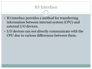

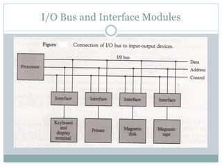


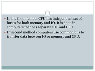
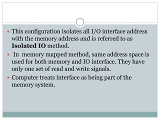

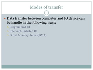
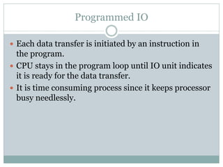
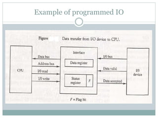
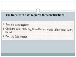

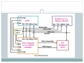
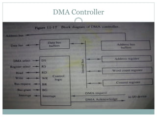


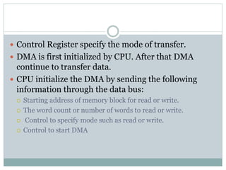

The document discusses input/output (I/O) interfaces in computer systems. It explains that I/O interfaces allow communication between internal system components like the CPU and external I/O devices. It also describes different I/O bus configurations, types of I/O commands, and methods of data transfer between the CPU and I/O devices like programmed I/O, interrupt-initiated I/O, and direct memory access (DMA). DMA allows I/O devices to directly access system memory without involving the CPU, improving performance.