Downloaded 3,311 times
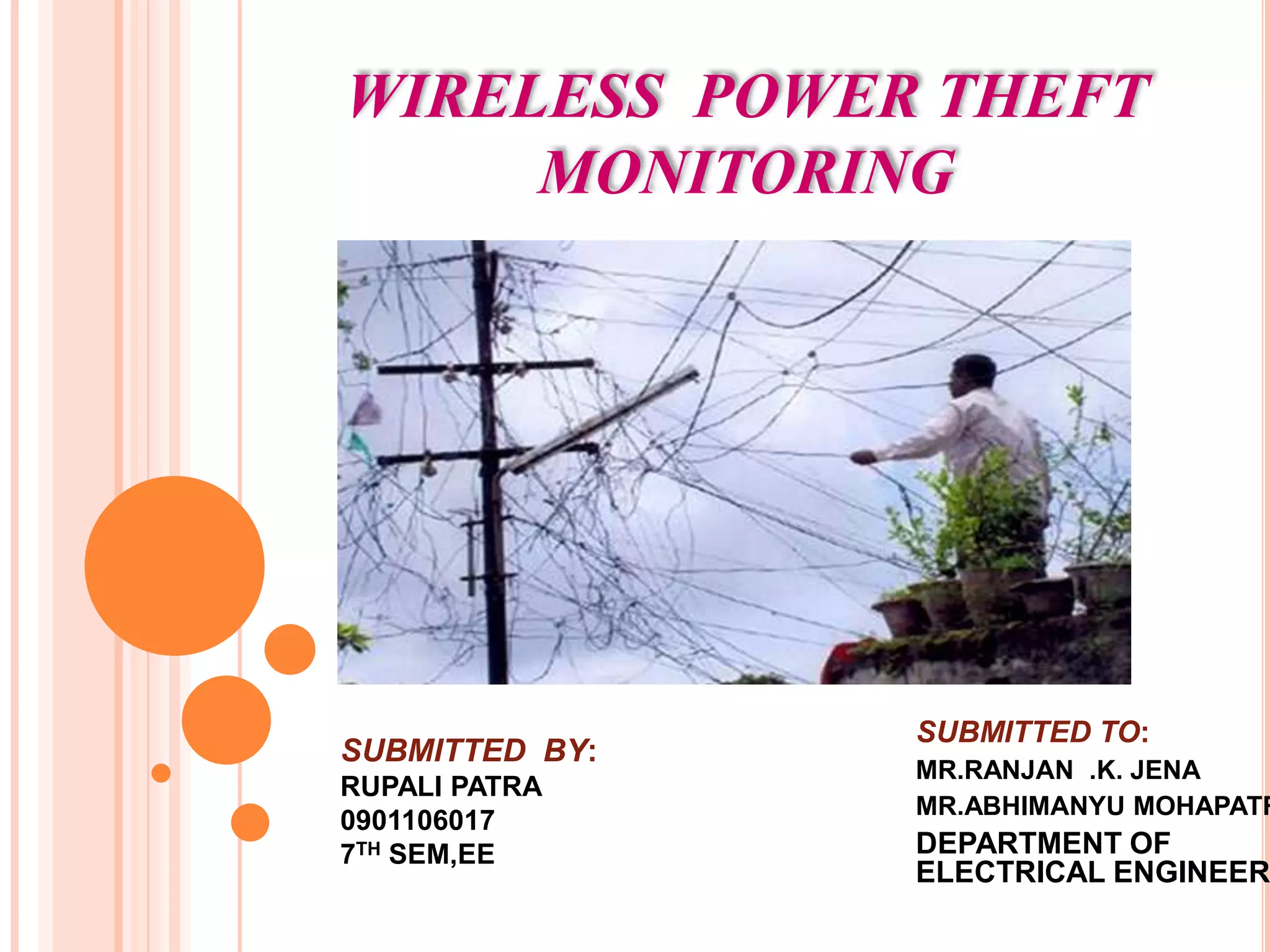


This document proposes a microcontroller-based wireless power theft monitoring system. The system uses wireless sensor nodes connected to consumers, transformers, and transmission lines to monitor power usage. If differences are detected between measured and reported usage, it could indicate power theft. The system aims to reduce energy wastage and theft by detecting where illegal usage occurs and notifying authorities. Some limitations are an inability to identify exact theft locations or individuals, and potential challenges implementing on a large scale.
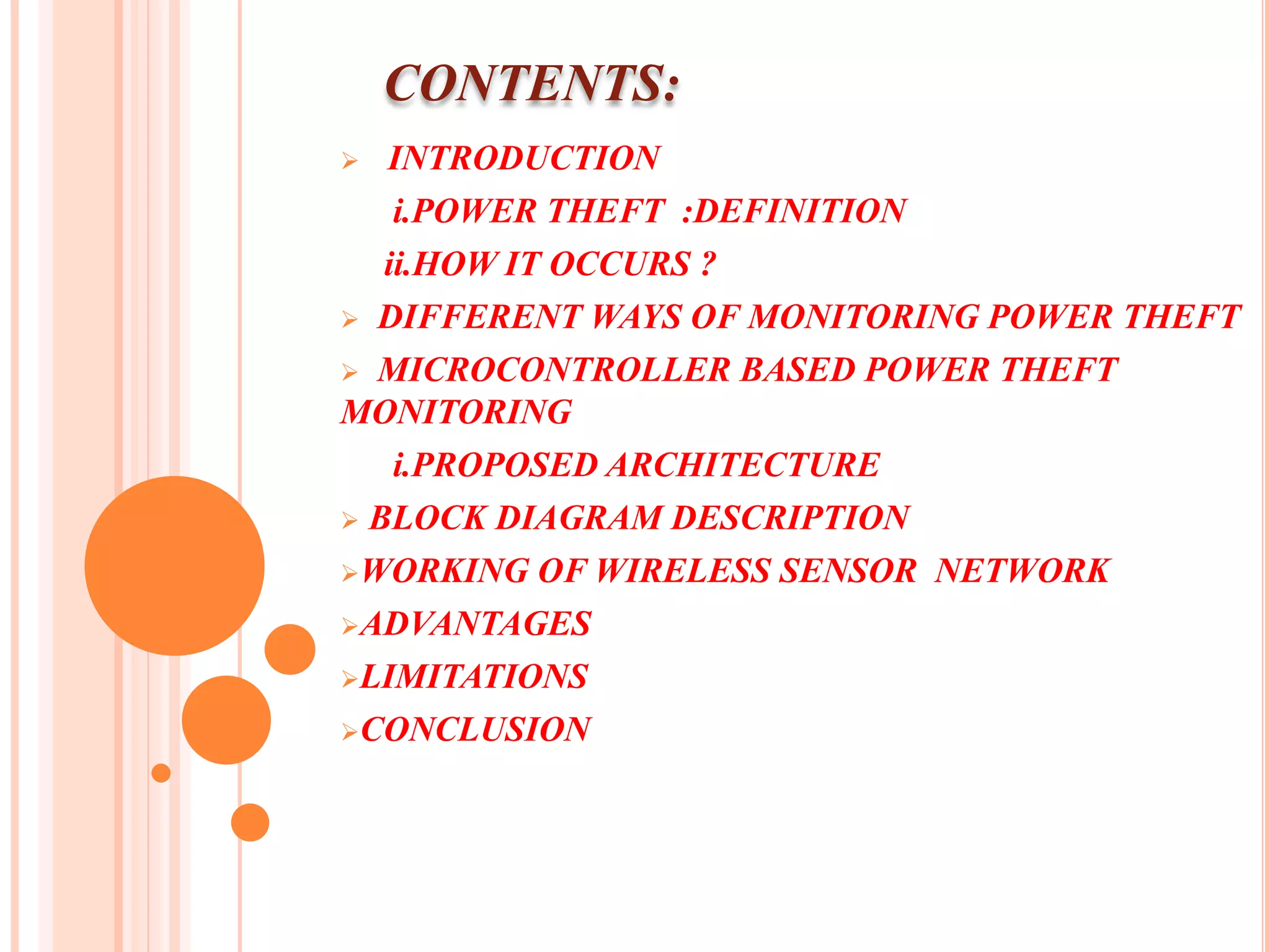
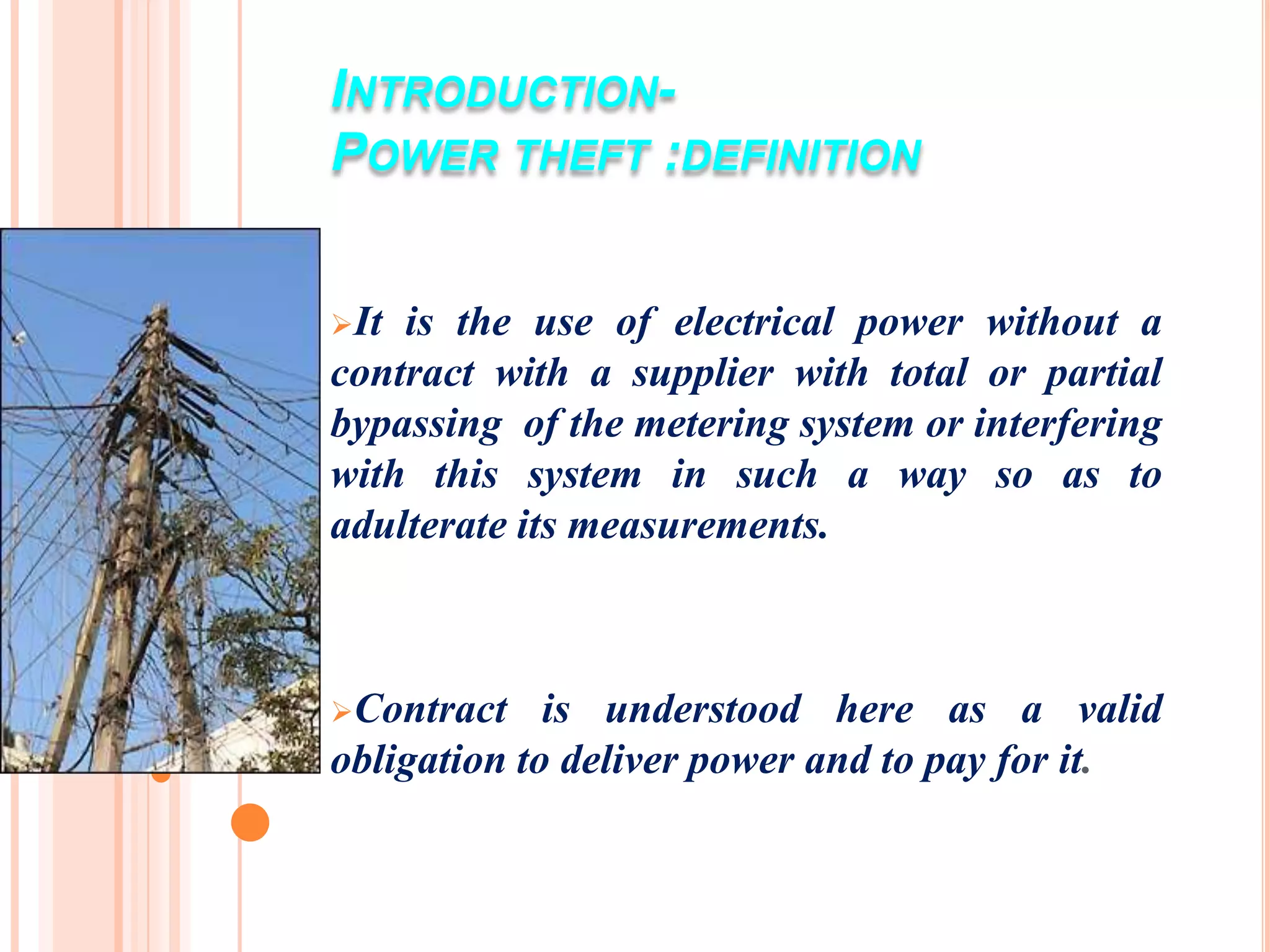
Introduces the topic of power theft, focusing on its definition and monitoring methods.
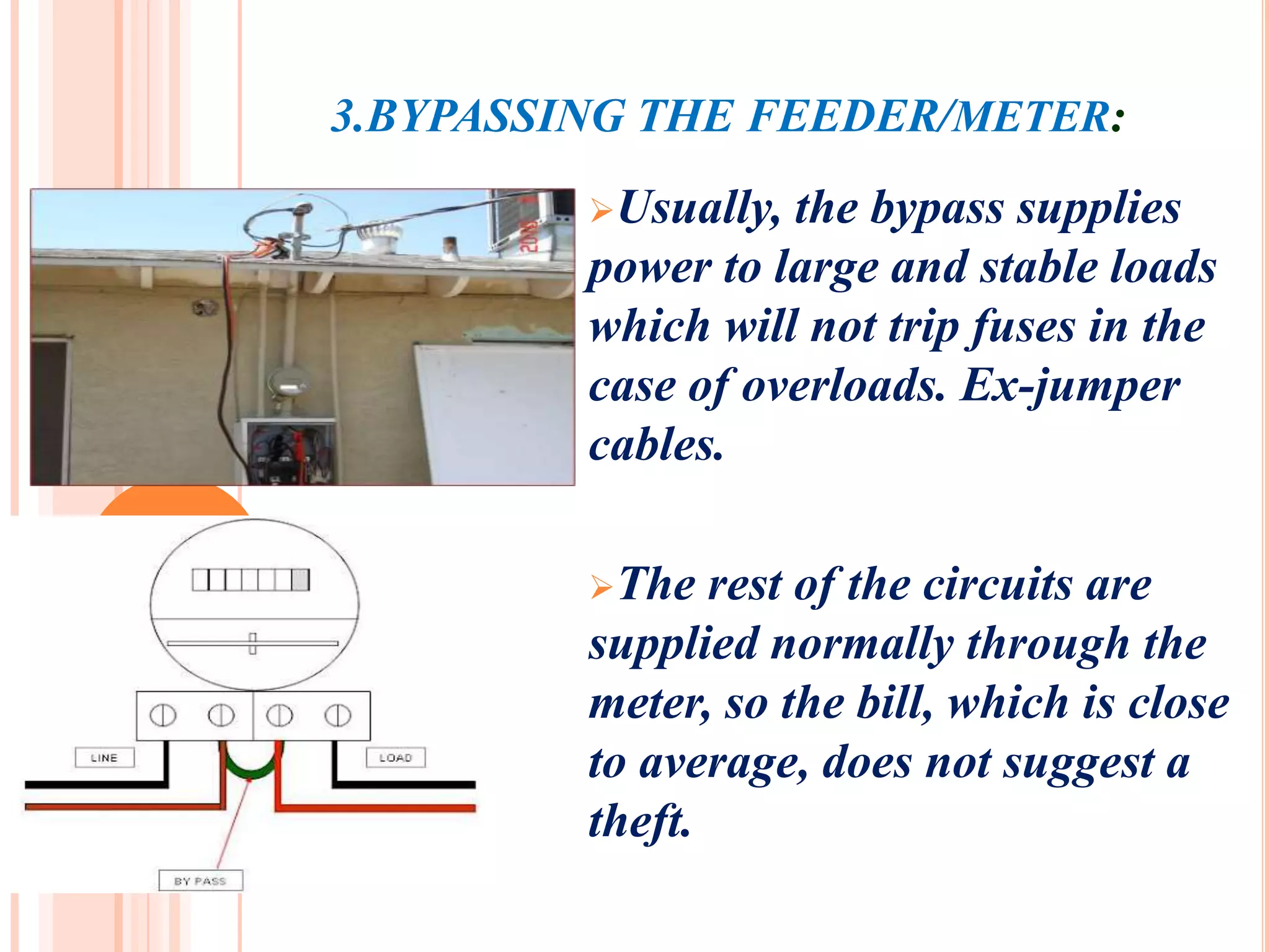
Describes power theft, including methods like slowing down meters, inverting meters, and bypassing systems.
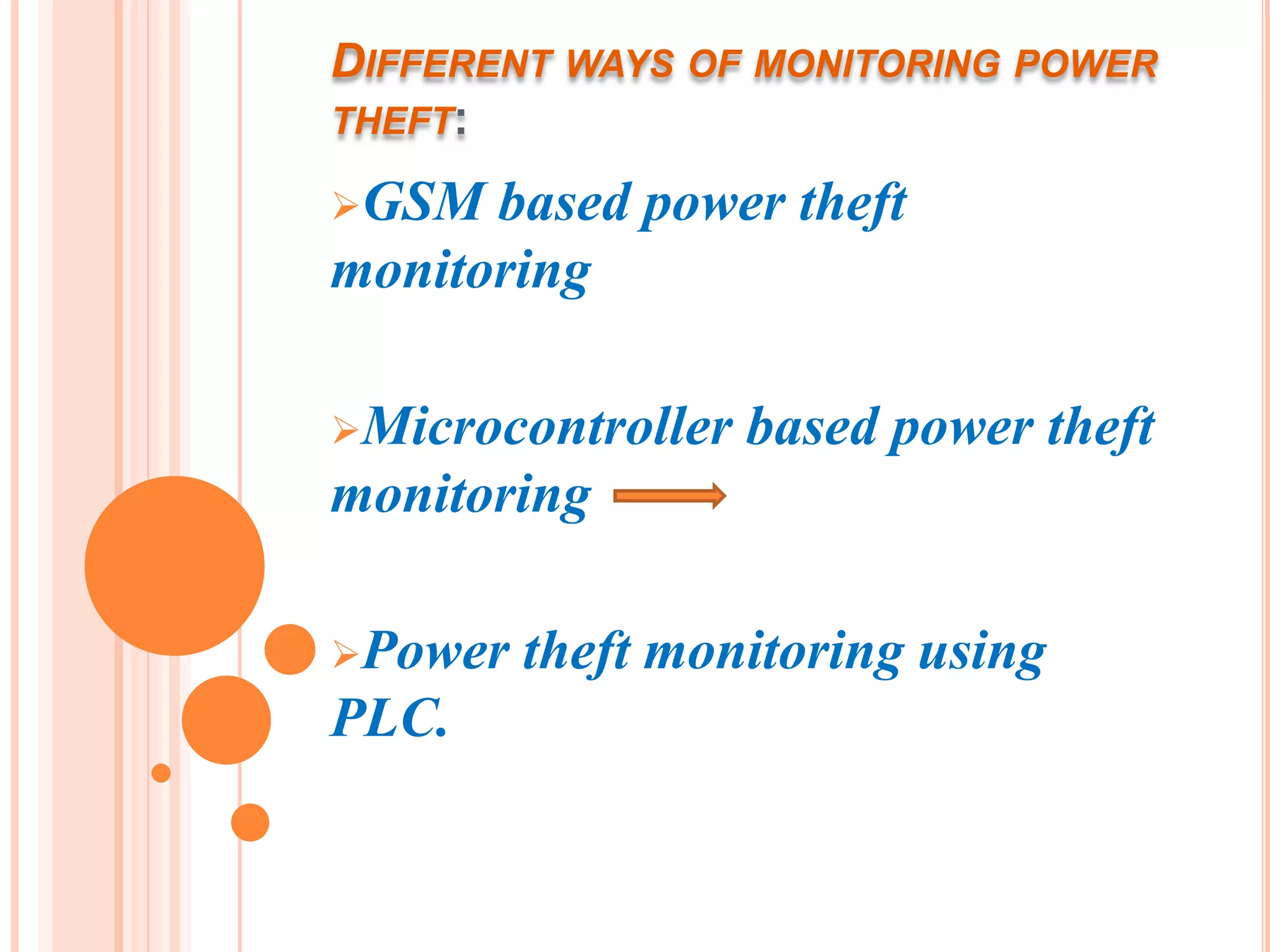
Overview of various monitoring techniques for power theft utilizing GSM, microcontrollers, and PLC.
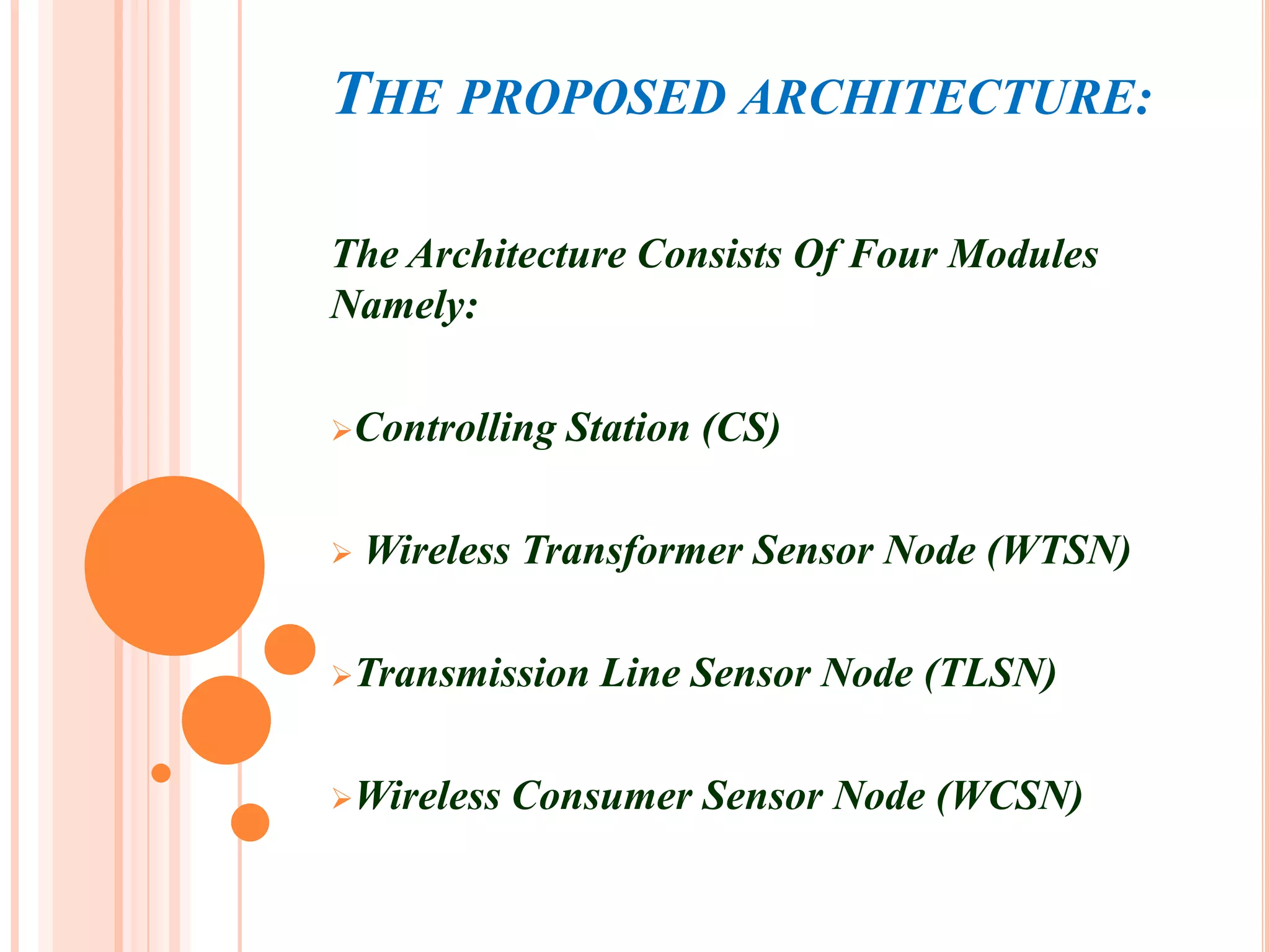
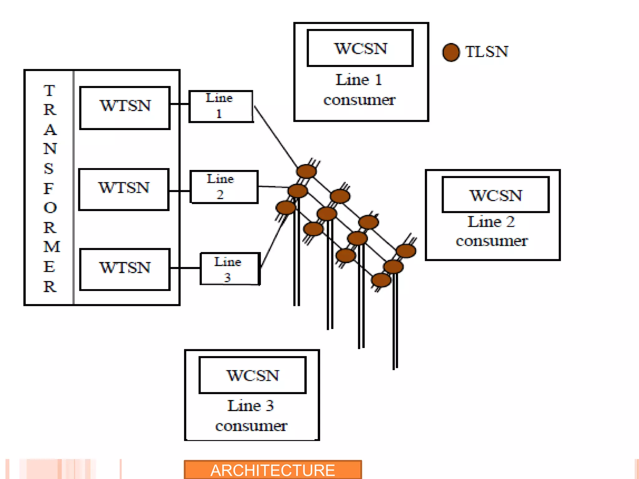
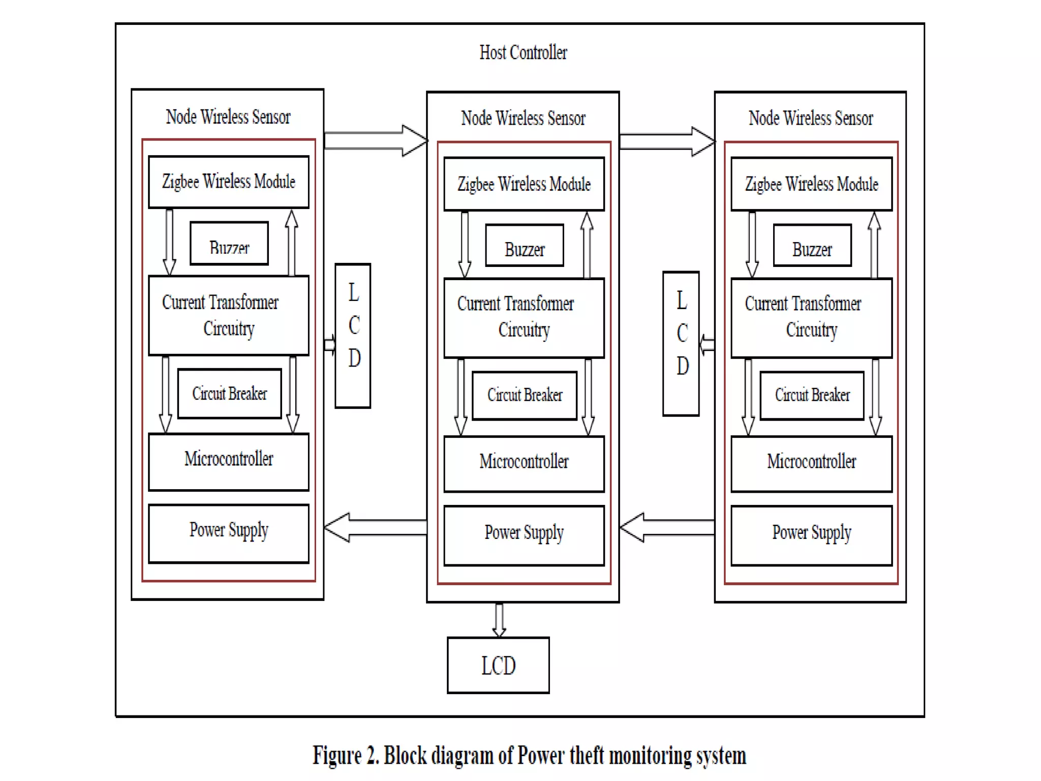
Details the architecture of the proposed system, which includes various modules and their functionalities.
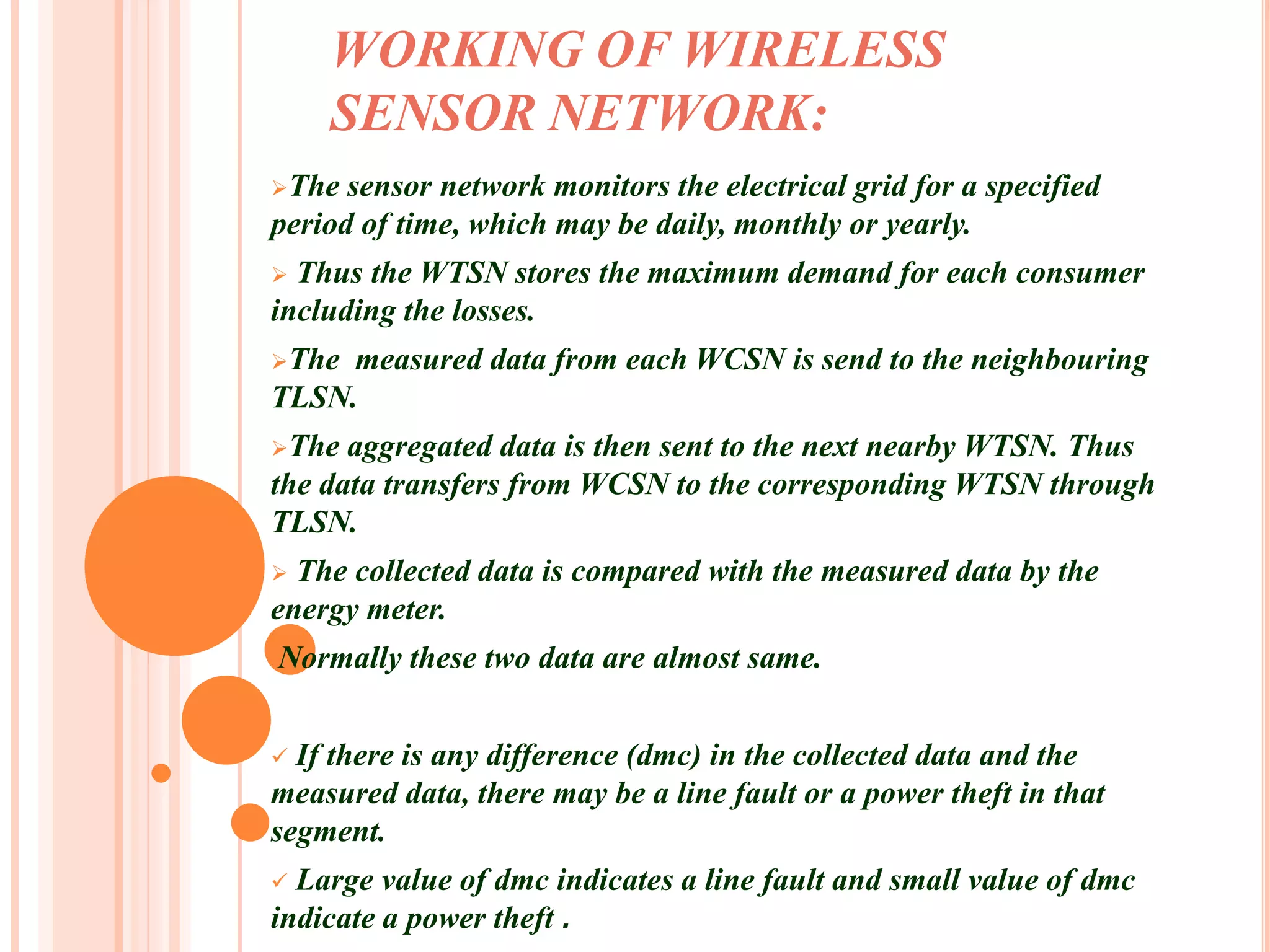
Explains how the sensor network operates, monitoring power theft and data aggregation.
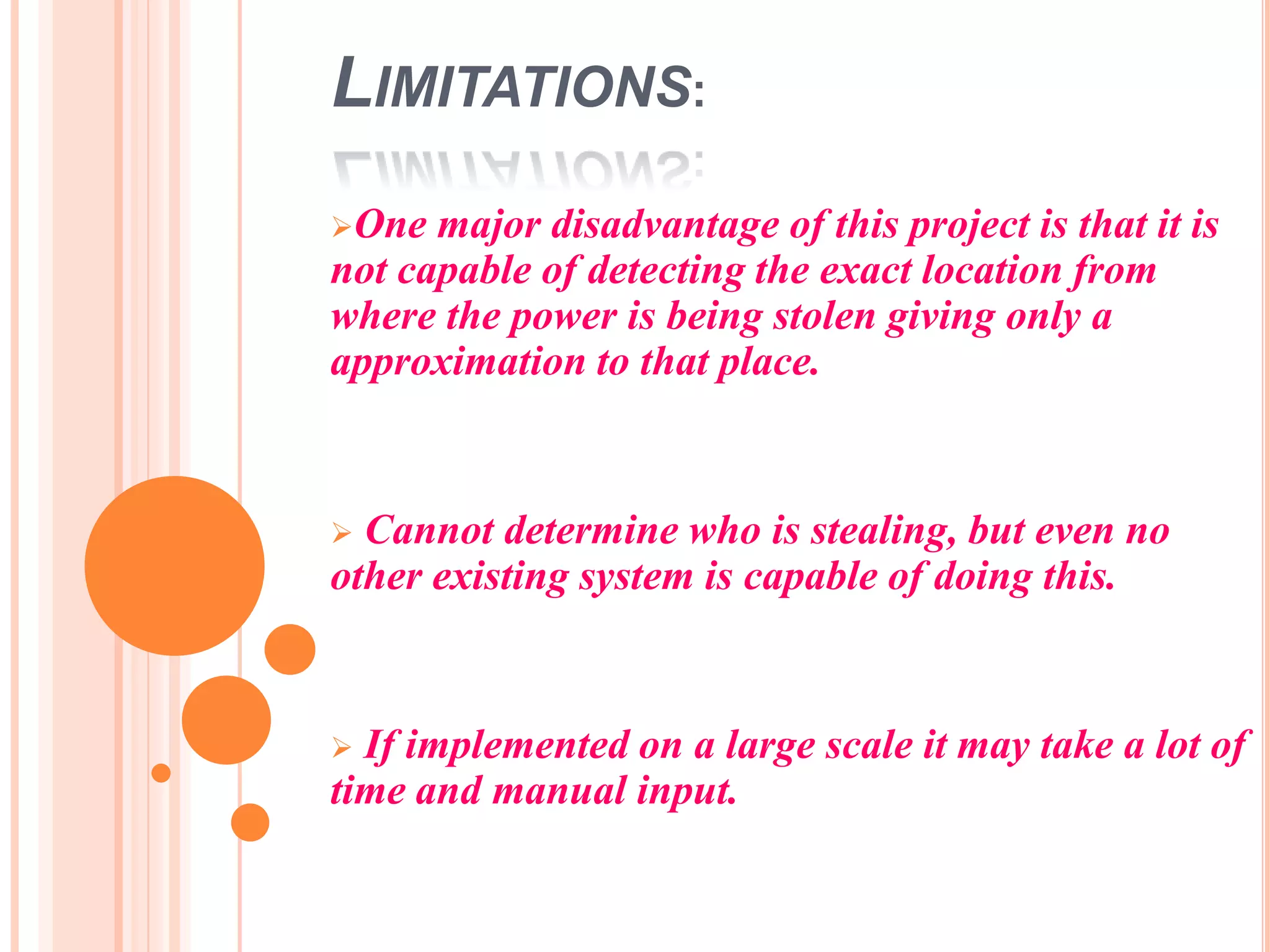
Highlights the advantages of the proposed system and discusses its limitations.
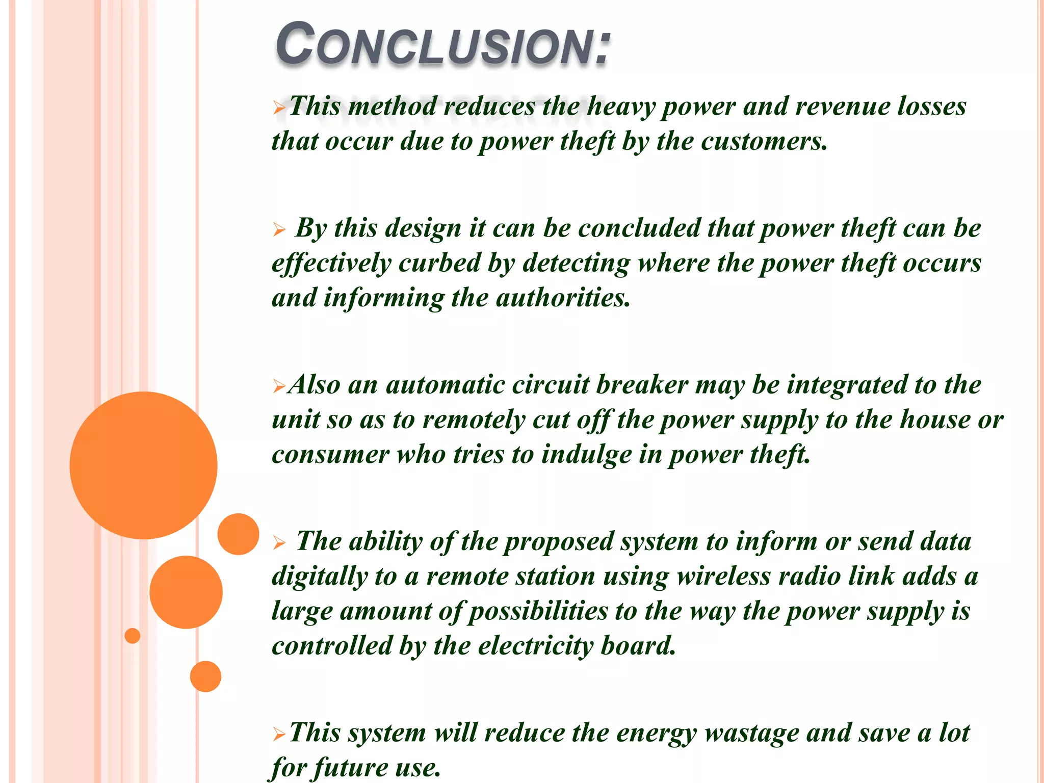
Concludes on the effectiveness of the monitoring system in combating power theft and suggests enhancements.