Phasor Measurement Units (PMUs) are devices that measure the magnitude and phase angle of electrical phasors in power grids using synchronized time sources like GPS, enabling real-time monitoring and enhancing the reliability of power systems. PMUs significantly improve the analysis of dynamic grid events, provide essential data for grid stability, and cater to applications such as adaptive relaying, state estimation, and fault location. As a critical component of smart grid technology, PMUs contribute to greater observability and control within electrical systems.
CLASS-4: PHASOR MEASUREMENTUNIT
(PMU)
Prof. (Dr.) Pravat Kumar Rout
Department of EEE
ITER
Siksha ‘O’ Anusandhan
(Deemed to be University),
Bhubaneswar, Odisha, India
Course: Distribution Generation and Smart Grid
Swetalina Sarangi
(Research Scholar)
Department of EE
ITER
Siksha ‘O’ Anusandhan
(Deemed to be University),
Bhubaneswar, Odisha, India
2.
WHAT IS PHASOR?
Phasor is a quantity with
magnitude and phase (with
respect to a reference) that is used
to represent a sinusoidal signal.
Here the phase or phase angle is
the distance between the signal’s
sinusoidal peak and a specified
reference and is expressed using
an angular measure.
Here, the reference is a fixed point
in time (such as time = 0).
The phasor magnitude is related to the
amplitude of the sinusoidal signal.
3.
WHAT IS PHASORMEASUREMENT UNIT?
A phasor measurement unit (PMU) is a device used to estimate the
magnitude and phase angle of an electrical phasor quantity (such as
voltage or current) in the electric grid using a common time source for
synchronization.
Time synchronization is usually provided by GPS and allows
synchronized real-time measurements of multiple remote points on the grid.
PMUs are capable of capturing samples from a waveform in quick
succession and reconstructing the phasor quantity, made up of an angle
measurement and a magnitude measurement.
The resulting measurement is known as a synchrophasor. These time
synchronized measurements are important because if the grid’s supply and
demand are not perfectly matched, frequency imbalances can cause stress on
the grid, which is a potential cause for power outages.
4.
CONTINUE...
PMUs canalso be used to measure the frequency in the power
grid.
A typical commercial PMU can report measurements with very high
temporal resolution in the order of 30-60 measurements per
second. This helps engineers in analyzing dynamic events in the grid
which is not possible with traditional SCADA measurements that
generate one measurement every 2 or 4 seconds.
Therefore, PMUs equip utilities with enhanced monitoring and
control capabilities and are considered to be one of the most
important measuring devices in the future of power systems.
A PMU can be a dedicated device, or the PMU function can be
incorporated into a protective relay or other device.
5.
WHY PMU?
PMUan essential component of Smart Grids.
It provides Synchrophasor data
Reports Magnitude, Phase and Frequency of an AC
waveform
Makes the grid observable due to high reporting rates
Preventive actions can be taken such as black outs
6.
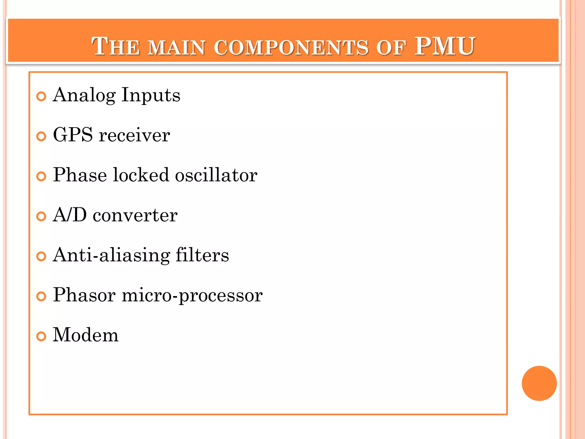
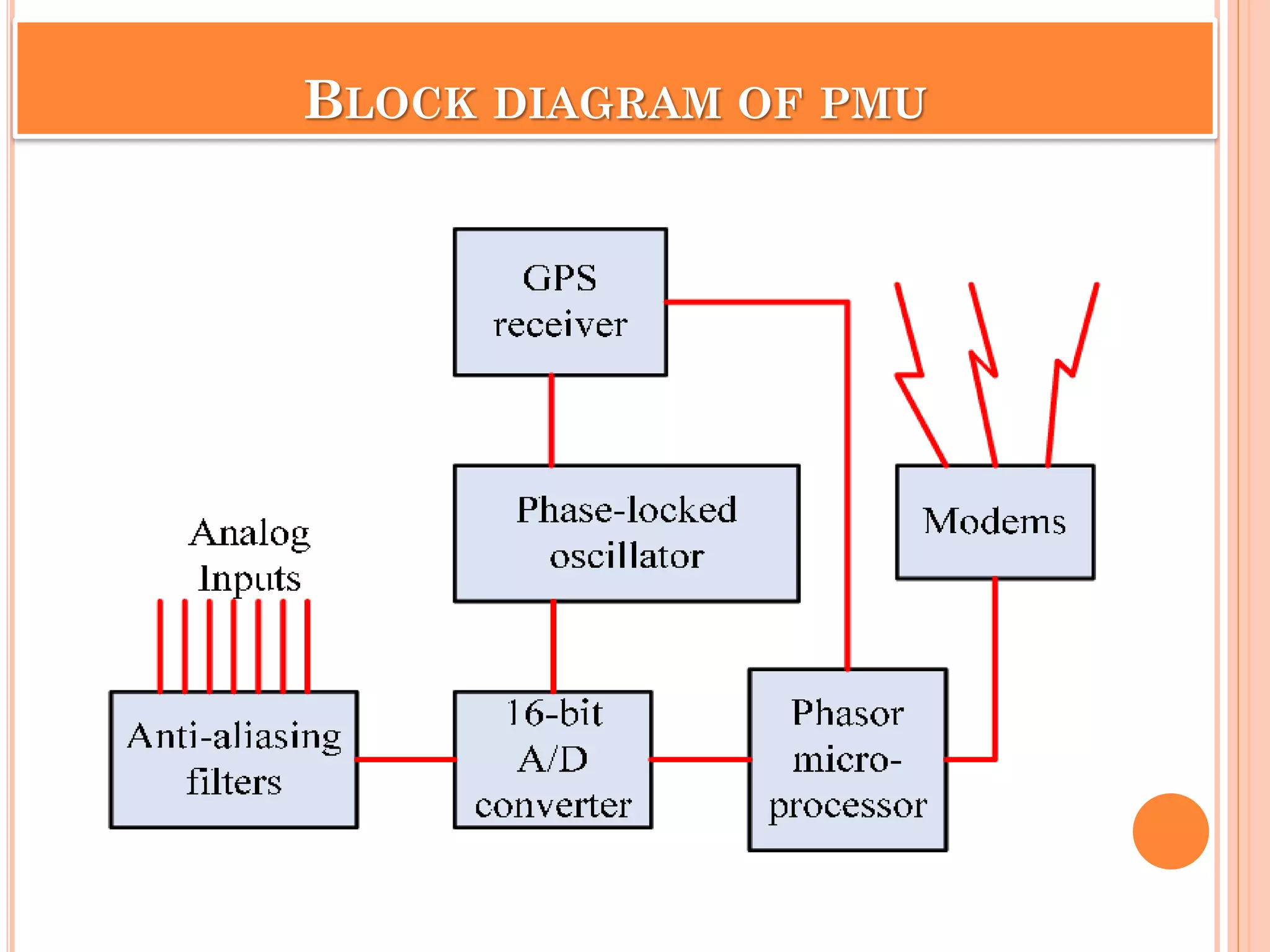
THE MAIN COMPONENTSOF PMU
Analog Inputs
GPS receiver
Phase locked oscillator
A/D converter
Anti-aliasing filters
Phasor micro-processor
Modem
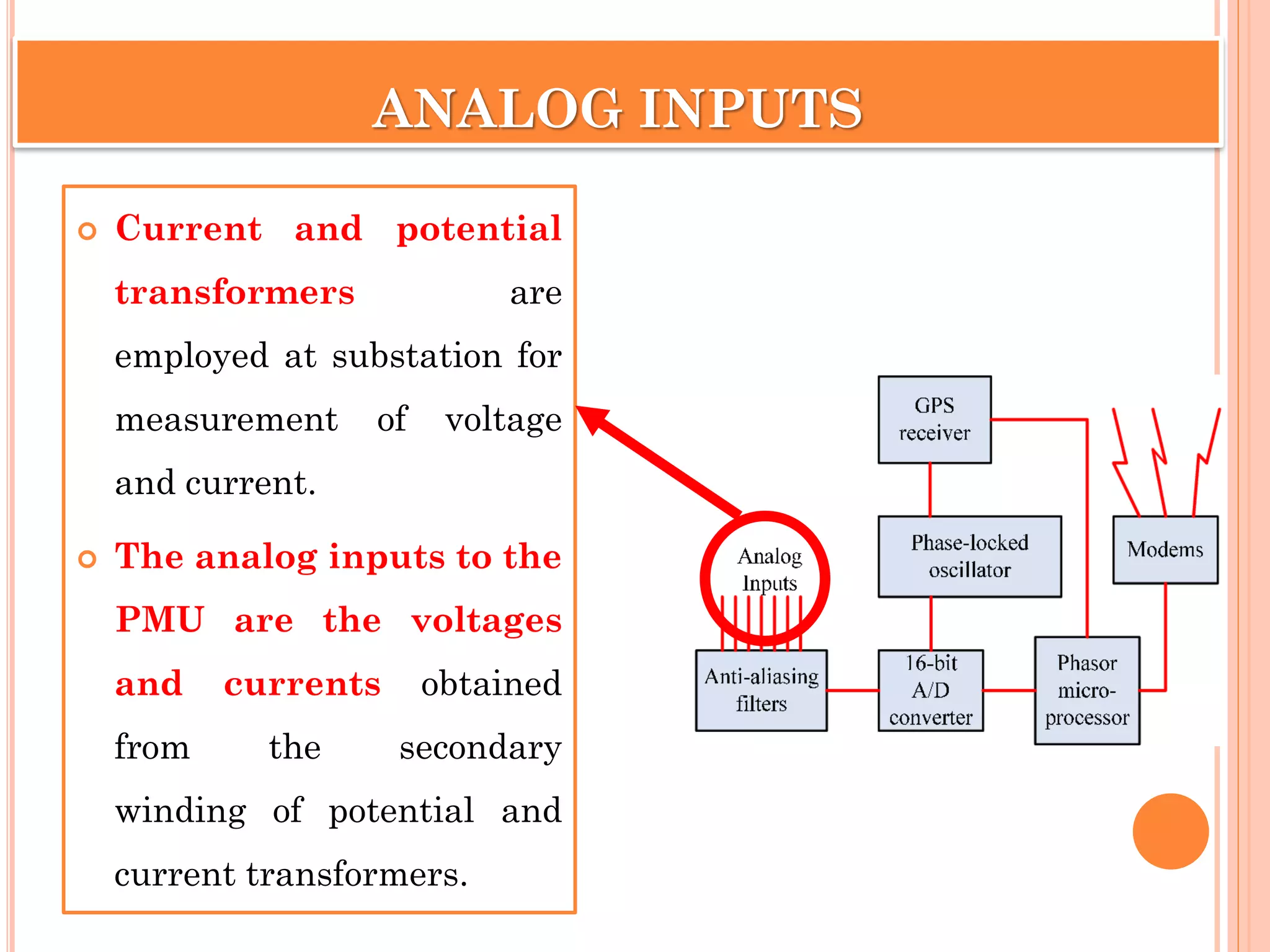
ANALOG INPUTS
Currentand potential
transformers are
employed at substation for
measurement of voltage
and current.
The analog inputs to the
PMU are the voltages
and currents obtained
from the secondary
winding of potential and
current transformers.
9.
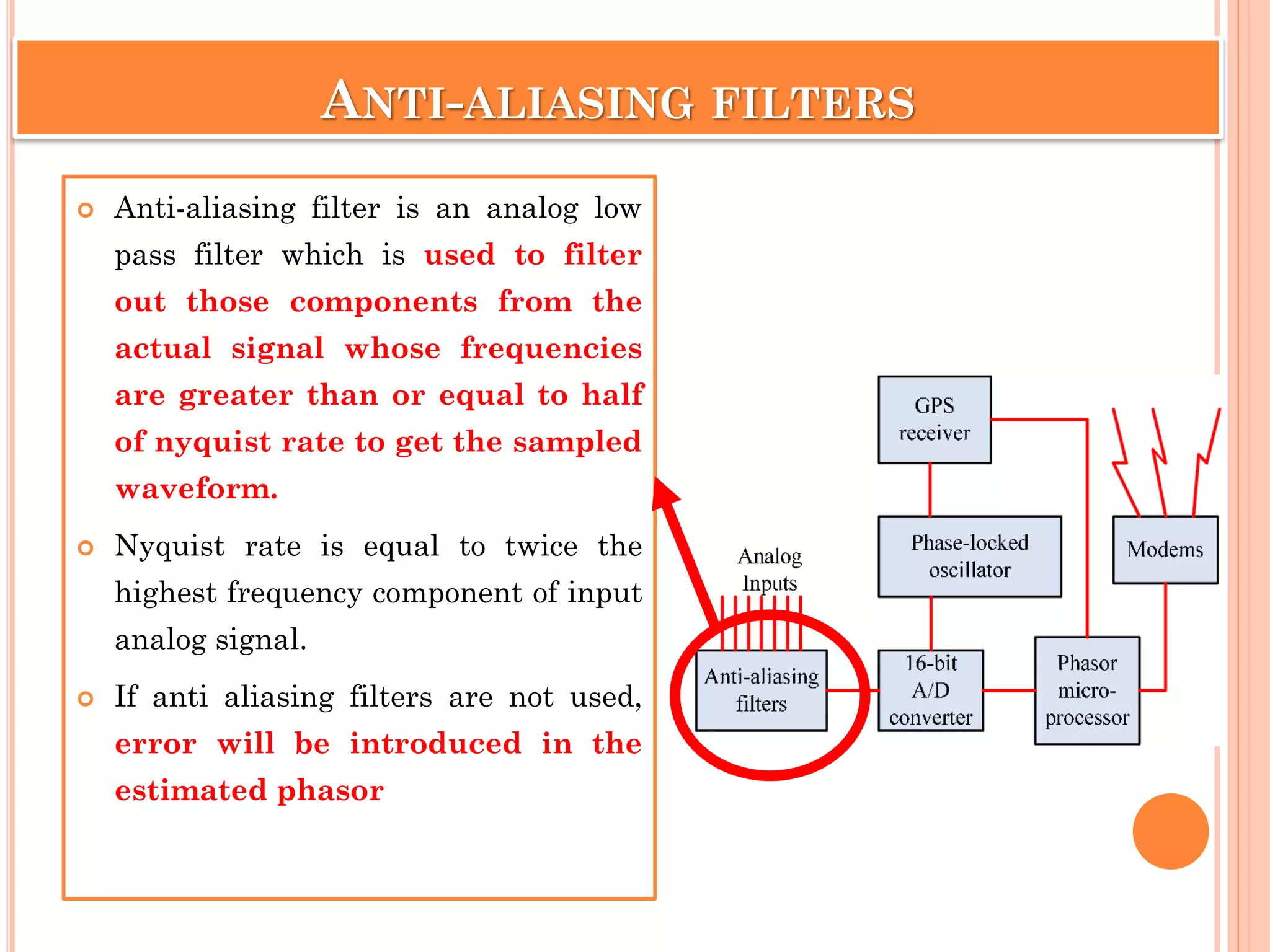
ANTI-ALIASING FILTERS
Anti-aliasingfilter is an analog low
pass filter which is used to filter
out those components from the
actual signal whose frequencies
are greater than or equal to half
of nyquist rate to get the sampled
waveform.
Nyquist rate is equal to twice the
highest frequency component of input
analog signal.
If anti aliasing filters are not used,
error will be introduced in the
estimated phasor
10.
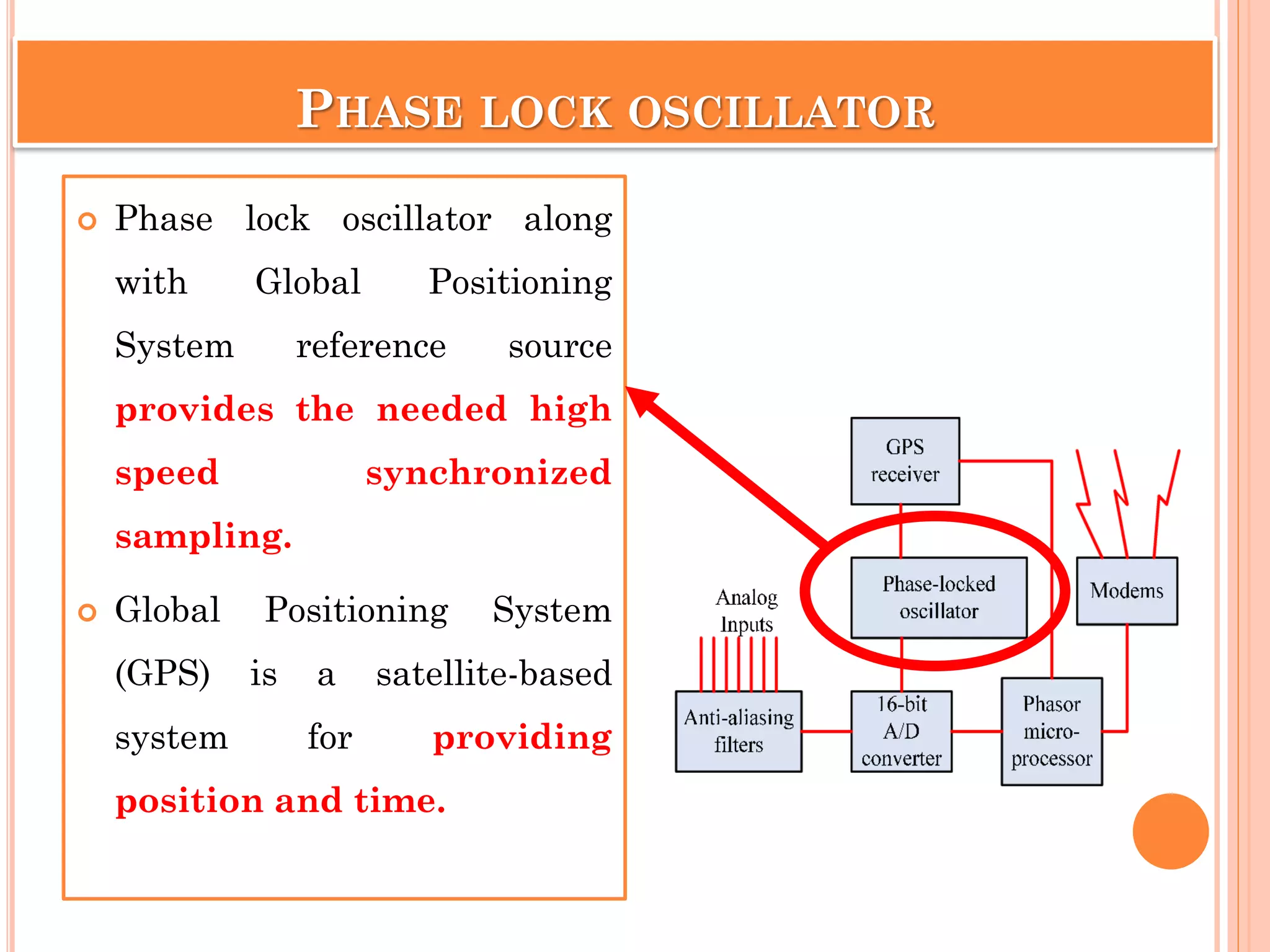
PHASE LOCK OSCILLATOR
Phase lock oscillator along
with Global Positioning
System reference source
provides the needed high
speed synchronized
sampling.
Global Positioning System
(GPS) is a satellite-based
system for providing
position and time.
11.
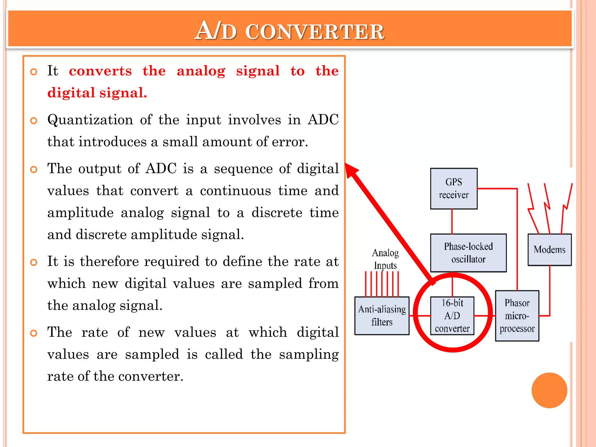
A/D CONVERTER
Itconverts the analog signal to the
digital signal.
Quantization of the input involves in ADC
that introduces a small amount of error.
The output of ADC is a sequence of digital
values that convert a continuous time and
amplitude analog signal to a discrete time
and discrete amplitude signal.
It is therefore required to define the rate at
which new digital values are sampled from
the analog signal.
The rate of new values at which digital
values are sampled is called the sampling
rate of the converter.
12.
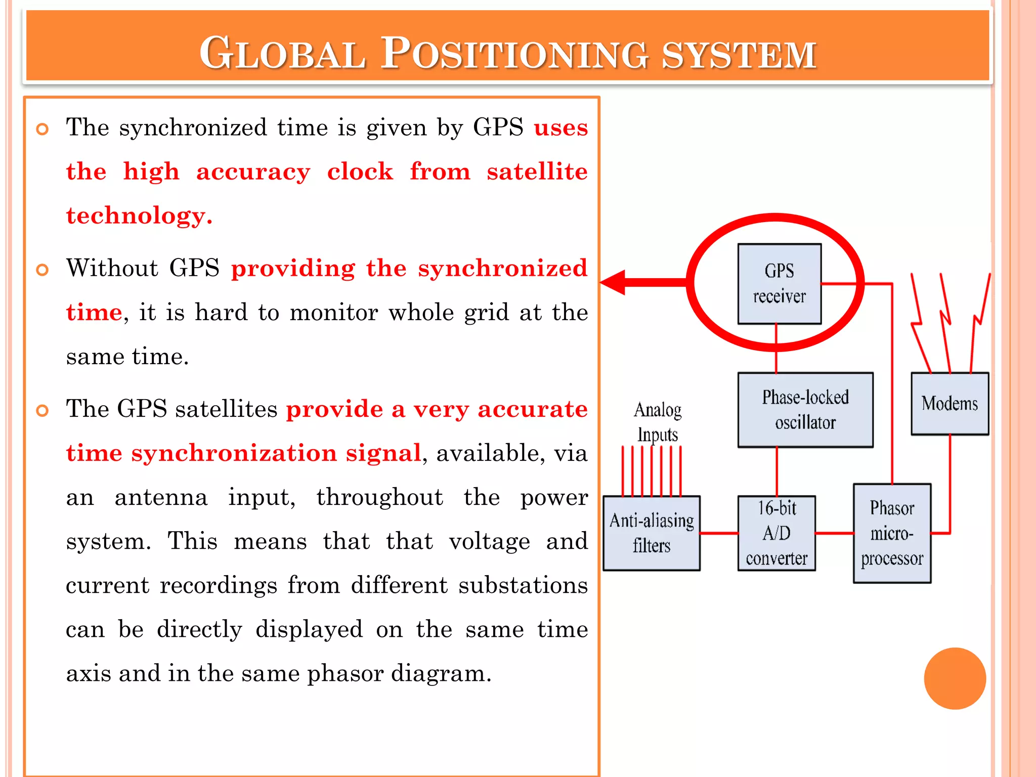
GLOBAL POSITIONING SYSTEM
The synchronized time is given by GPS uses
the high accuracy clock from satellite
technology.
Without GPS providing the synchronized
time, it is hard to monitor whole grid at the
same time.
The GPS satellites provide a very accurate
time synchronization signal, available, via
an antenna input, throughout the power
system. This means that that voltage and
current recordings from different substations
can be directly displayed on the same time
axis and in the same phasor diagram.
13.
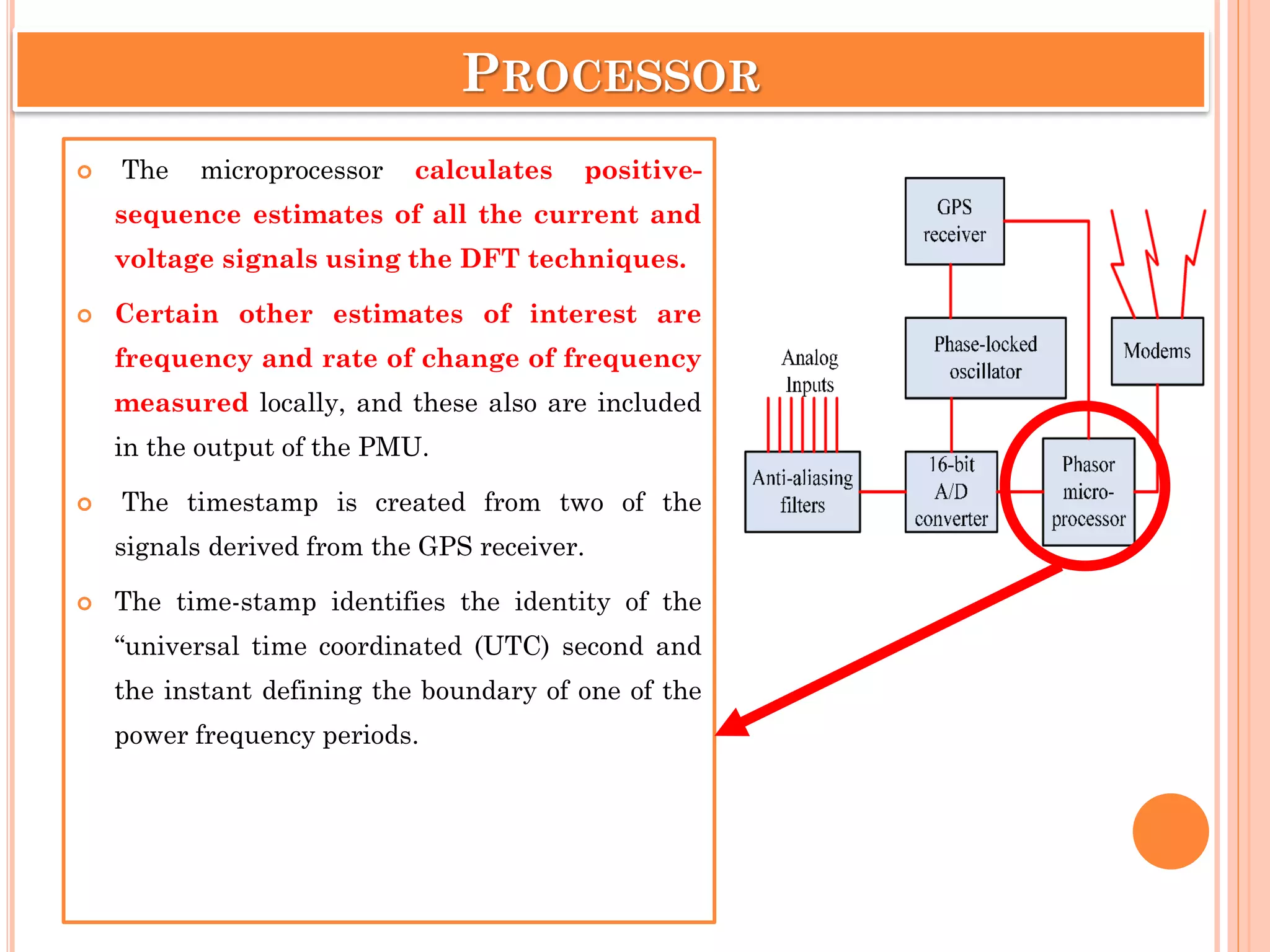
PROCESSOR
The microprocessorcalculates positive-
sequence estimates of all the current and
voltage signals using the DFT techniques.
Certain other estimates of interest are
frequency and rate of change of frequency
measured locally, and these also are included
in the output of the PMU.
The timestamp is created from two of the
signals derived from the GPS receiver.
The time-stamp identifies the identity of the
“universal time coordinated (UTC) second and
the instant defining the boundary of one of the
power frequency periods.
14.
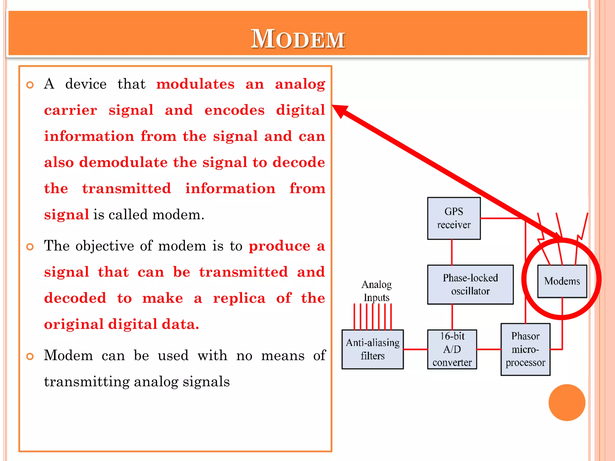
MODEM
A devicethat modulates an analog
carrier signal and encodes digital
information from the signal and can
also demodulate the signal to decode
the transmitted information from
signal is called modem.
The objective of modem is to produce a
signal that can be transmitted and
decoded to make a replica of the
original digital data.
Modem can be used with no means of
transmitting analog signals
15.
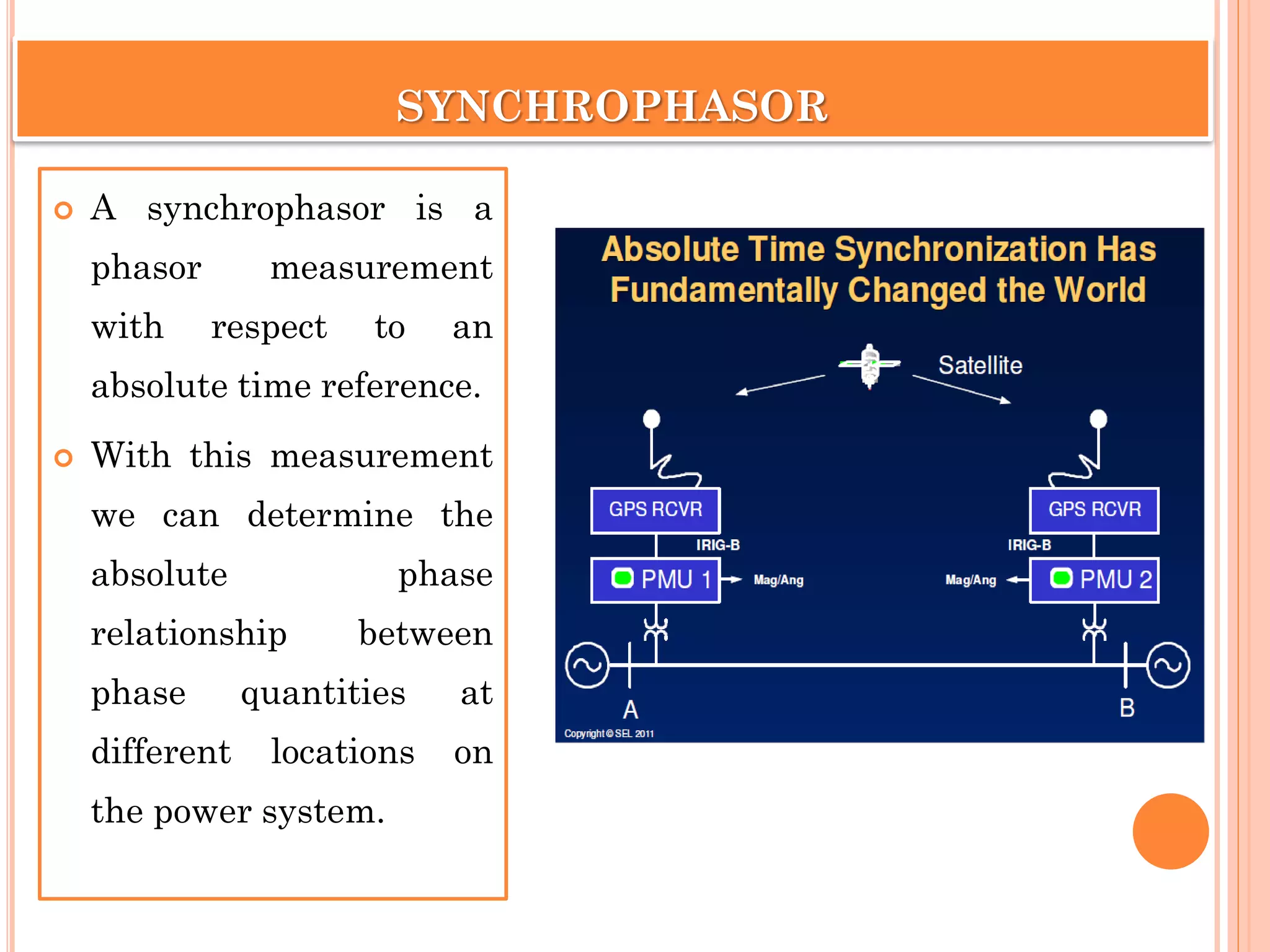
SYNCHROPHASOR
A synchrophasoris a
phasor measurement
with respect to an
absolute time reference.
With this measurement
we can determine the
absolute phase
relationship between
phase quantities at
different locations on
the power system.
FEATURES OF PMUS
PMUs are Measures 50/60 Hz AC waveforms (voltage and
current) typically at a rate of 48 samples per cycle.
PMUs are then computed using DFT-like algorithms, and time
stamped with a GPS.
The resultant time tagged PMUs can be transmitted to a local
or remote receiver at rates up to 60 samples per cycle.
19.
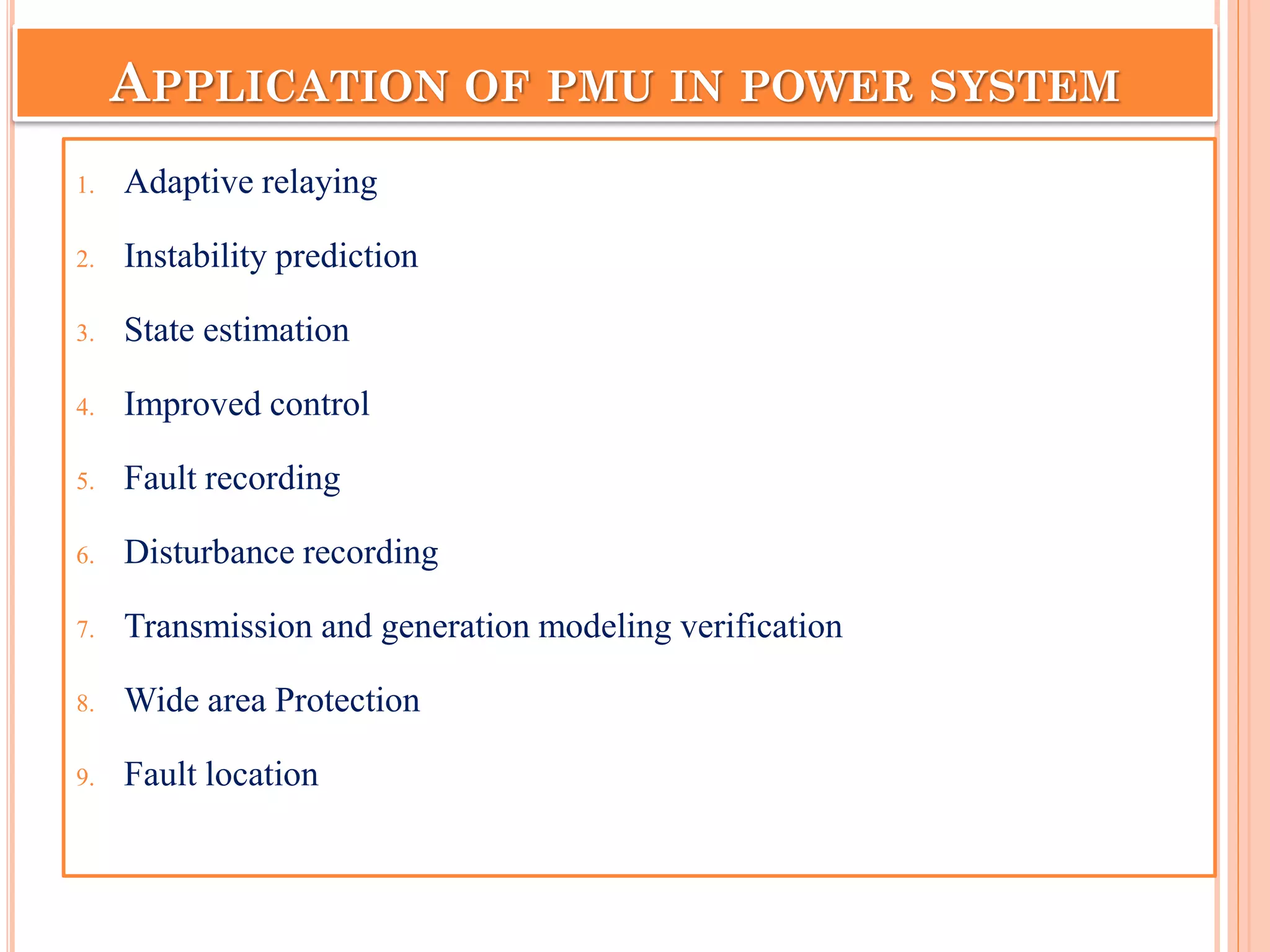
APPLICATION OF PMUIN POWER SYSTEM
1. Adaptive relaying
2. Instability prediction
3. State estimation
4. Improved control
5. Fault recording
6. Disturbance recording
7. Transmission and generation modeling verification
8. Wide area Protection
9. Fault location
20.
Adaptive Relaying
Adaptive relayingis a
protection philosophy which
permits and seeks to make
adjustments in various
protection functions in order to
make them more tuned to
prevailing power system
conditions
21.
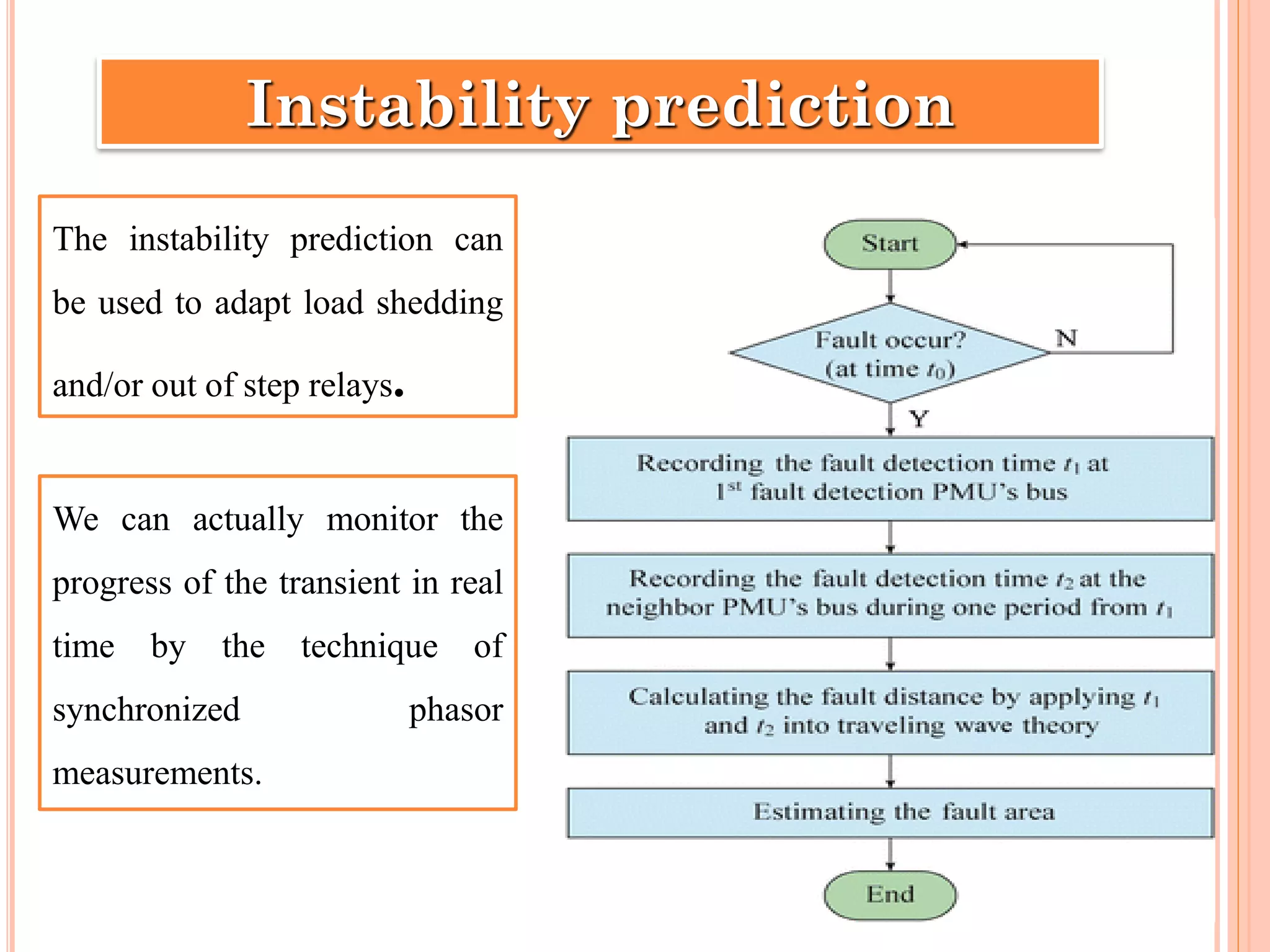
Instability prediction
The instabilityprediction can
be used to adapt load shedding
and/or out of step relays.
We can actually monitor the
progress of the transient in real
time by the technique of
synchronized phasor
measurements.
22.
• The stateestimator uses various measurements received from
different substations, and, through an iterative nonlinear
estimation procedure, calculates the power system state.
State estimation
• By maintaining a continuous stream of phasor data from the
substations to the control center, a state vector that can follow the
system dynamics can be constructed.
• For the first time in history, synchronized phasor measurements
have made possible the direct observation of system
oscillations following system disturbances.
23.
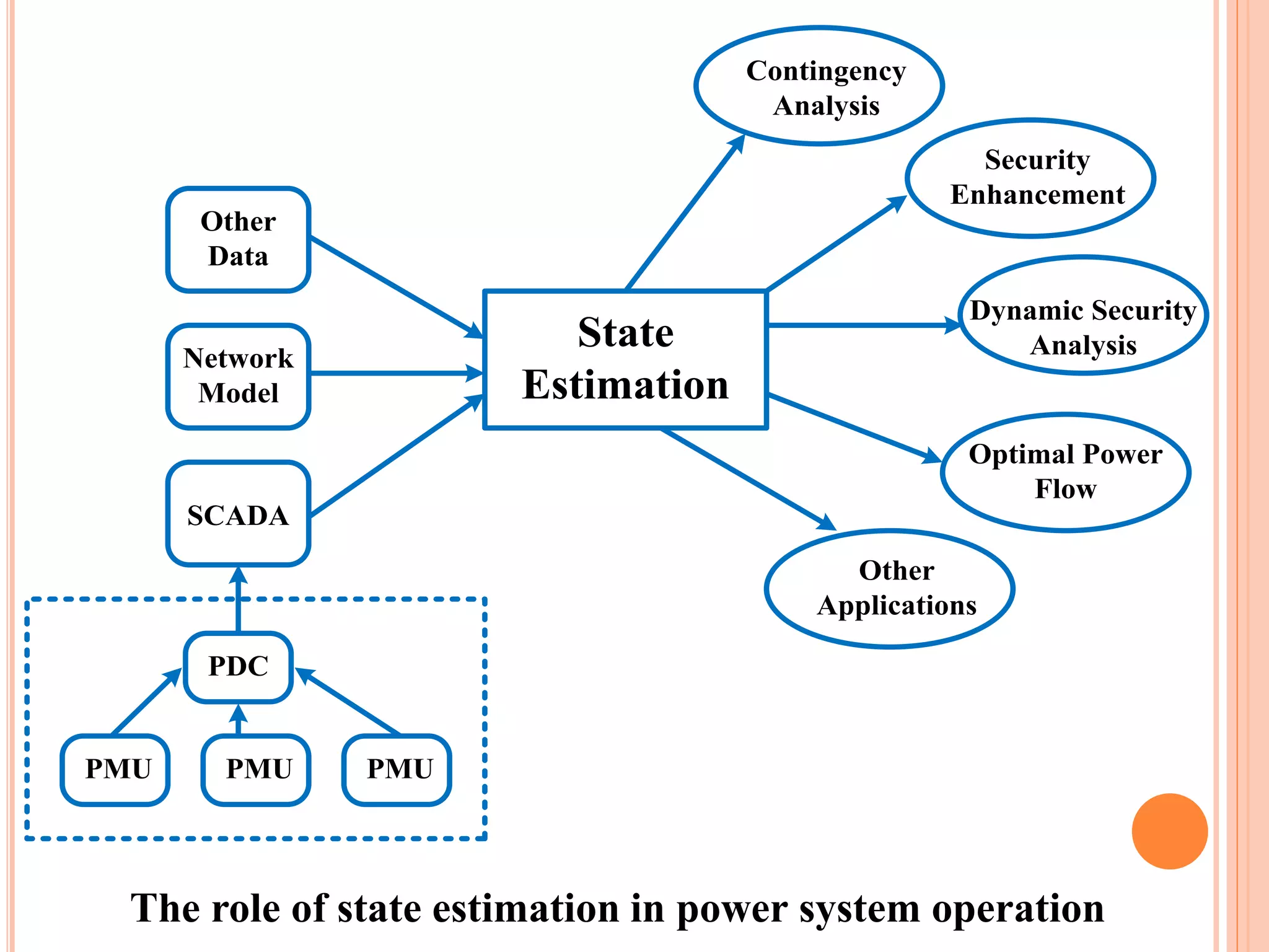
The role ofstate estimation in power system operation
Contingency
Analysis
Security
Enhancement
Dynamic Security
Analysis
Optimal Power
Flow
Other
Applications
State
Estimation
Other
Data
Network
Model
SCADA
PDC
PMU PMUPMU
24.
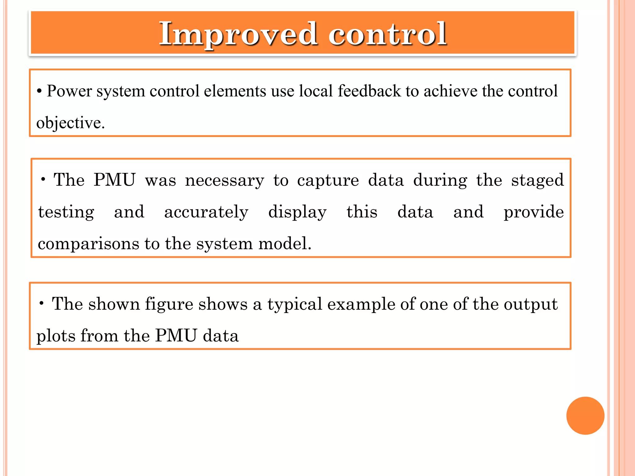
• Power systemcontrol elements use local feedback to achieve the control
objective.
Improved control
• The PMU was necessary to capture data during the staged
testing and accurately display this data and provide
comparisons to the system model.
• The shown figure shows a typical example of one of the output
plots from the PMU data
26.
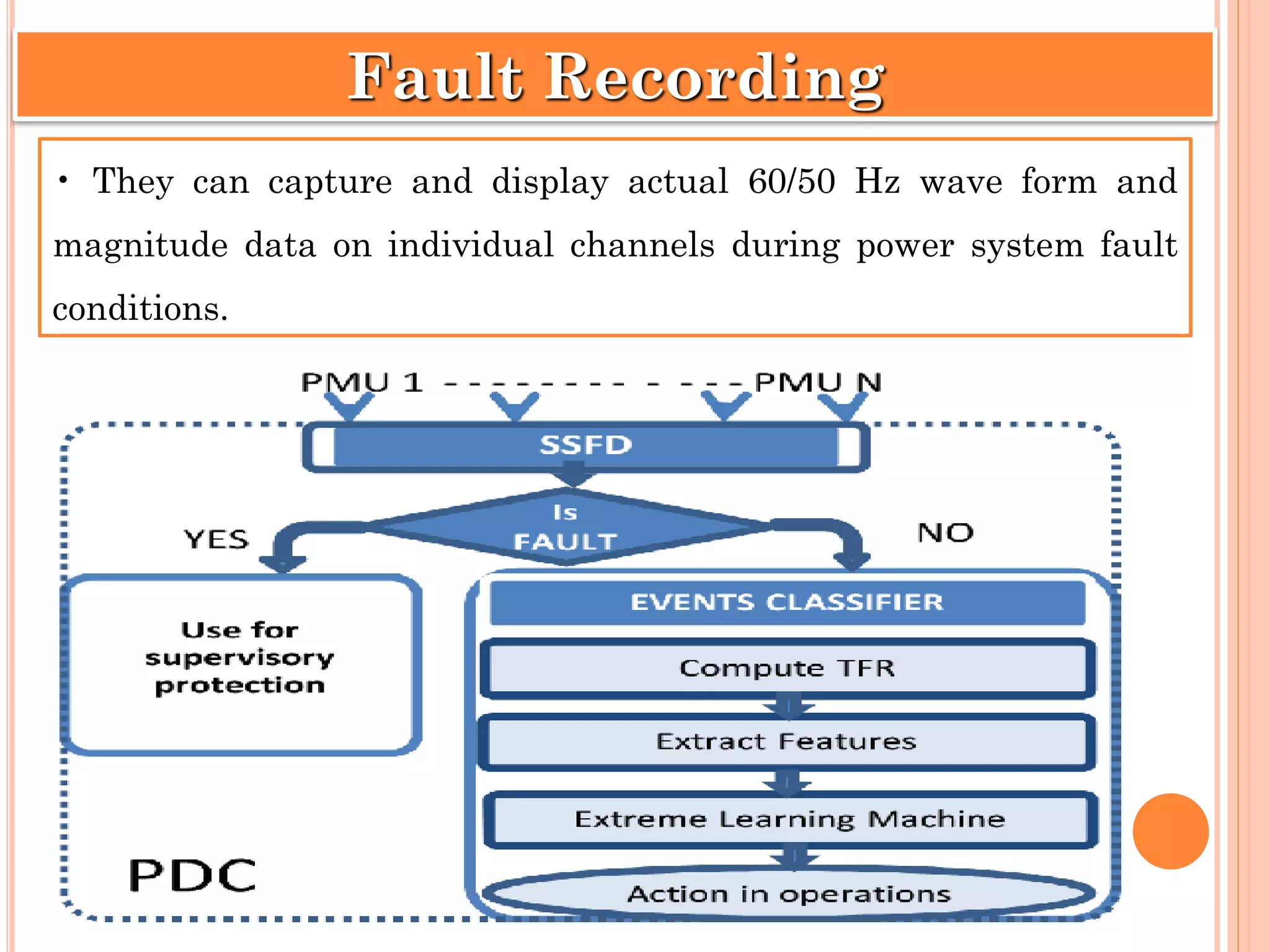
• They cancapture and display actual 60/50 Hz wave form and
magnitude data on individual channels during power system fault
conditions.
Fault Recording
27.
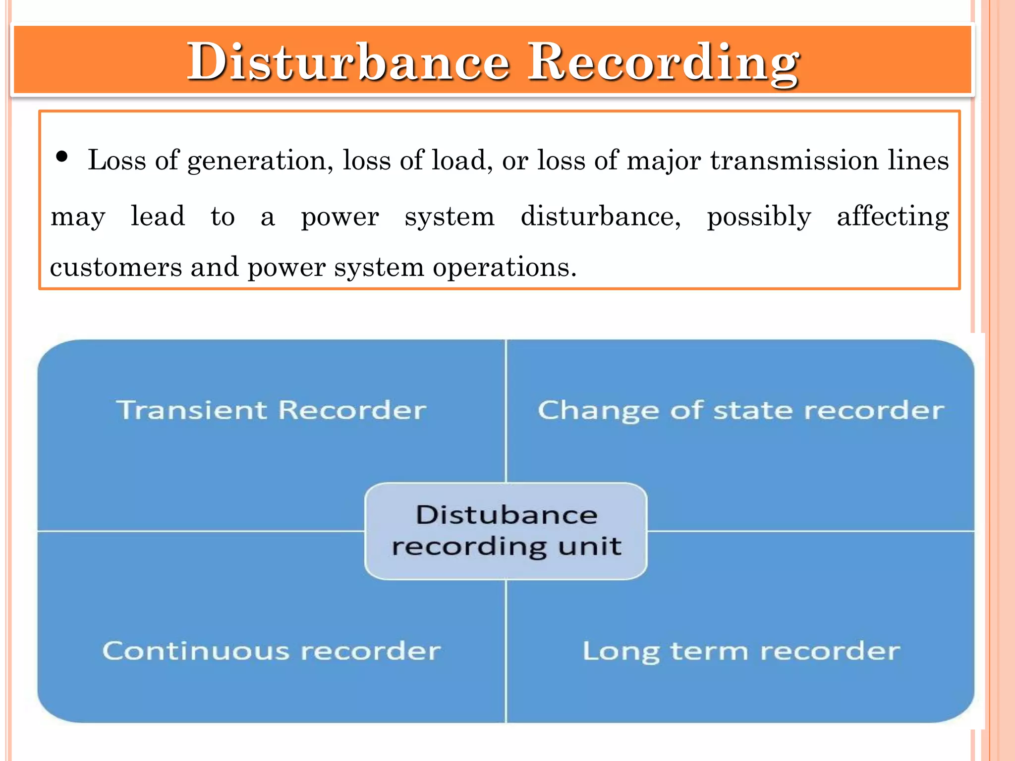
• Loss ofgeneration, loss of load, or loss of major transmission lines
may lead to a power system disturbance, possibly affecting
customers and power system operations.
Disturbance Recording
28.
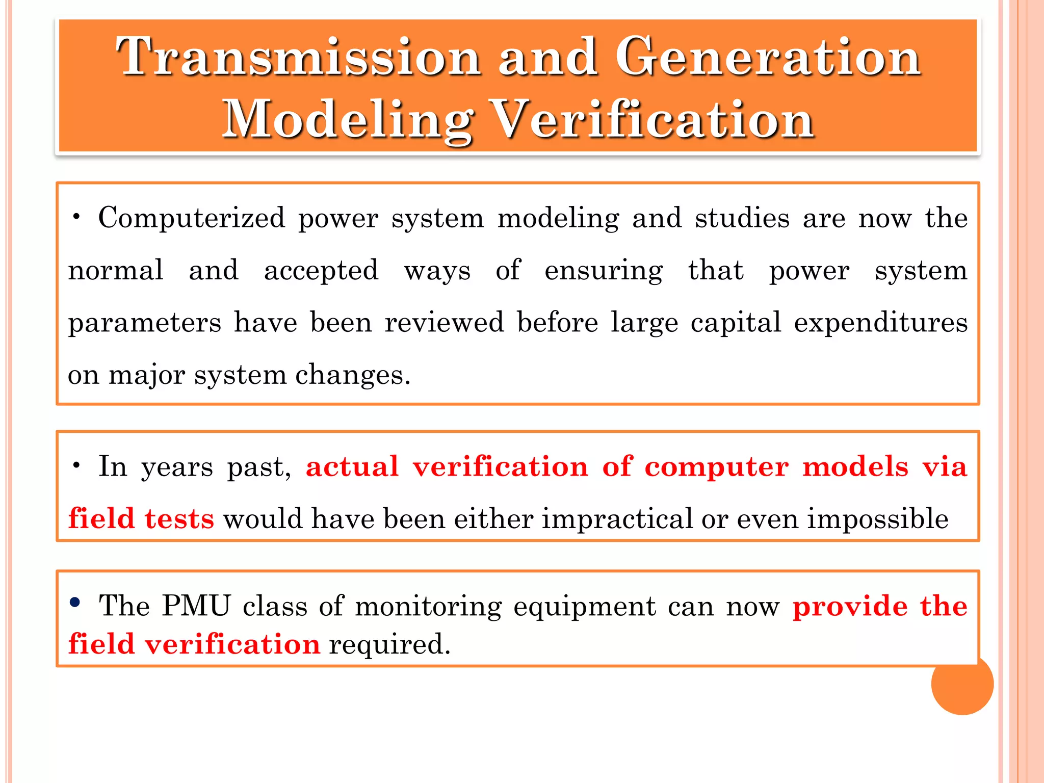
• Computerized powersystem modeling and studies are now the
normal and accepted ways of ensuring that power system
parameters have been reviewed before large capital expenditures
on major system changes.
Transmission and Generation
Modeling Verification
• In years past, actual verification of computer models via
field tests would have been either impractical or even impossible
• The PMU class of monitoring equipment can now provide the
field verification required.
29.
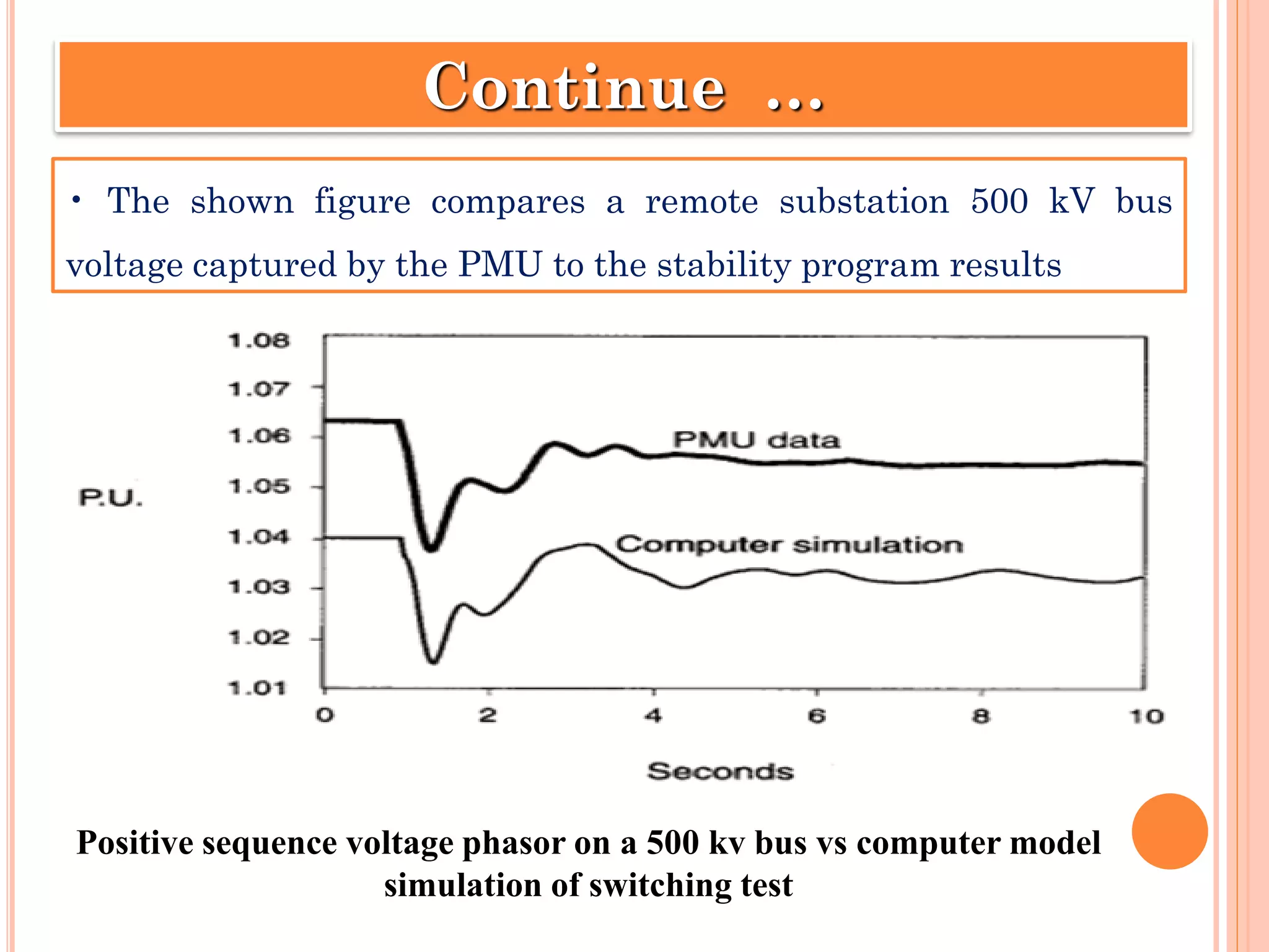
• The shownfigure compares a remote substation 500 kV bus
voltage captured by the PMU to the stability program results
Continue …
Positive sequence voltage phasor on a 500 kv bus vs computer model
simulation of switching test
30.
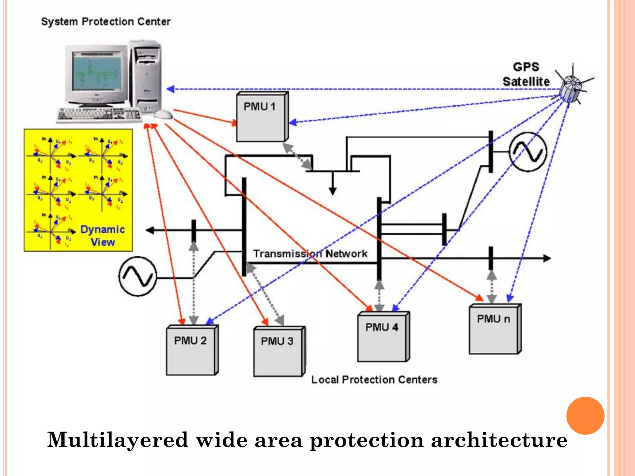
The introduction ofthe Phasor Measurement Unit (PMU) has
greatly improved the observability of the power system
dynamics. Based on PMUs, different kinds of wide area
protection, emergency control and optimization systems can be
designed
WIDE – AREA PROTECTION
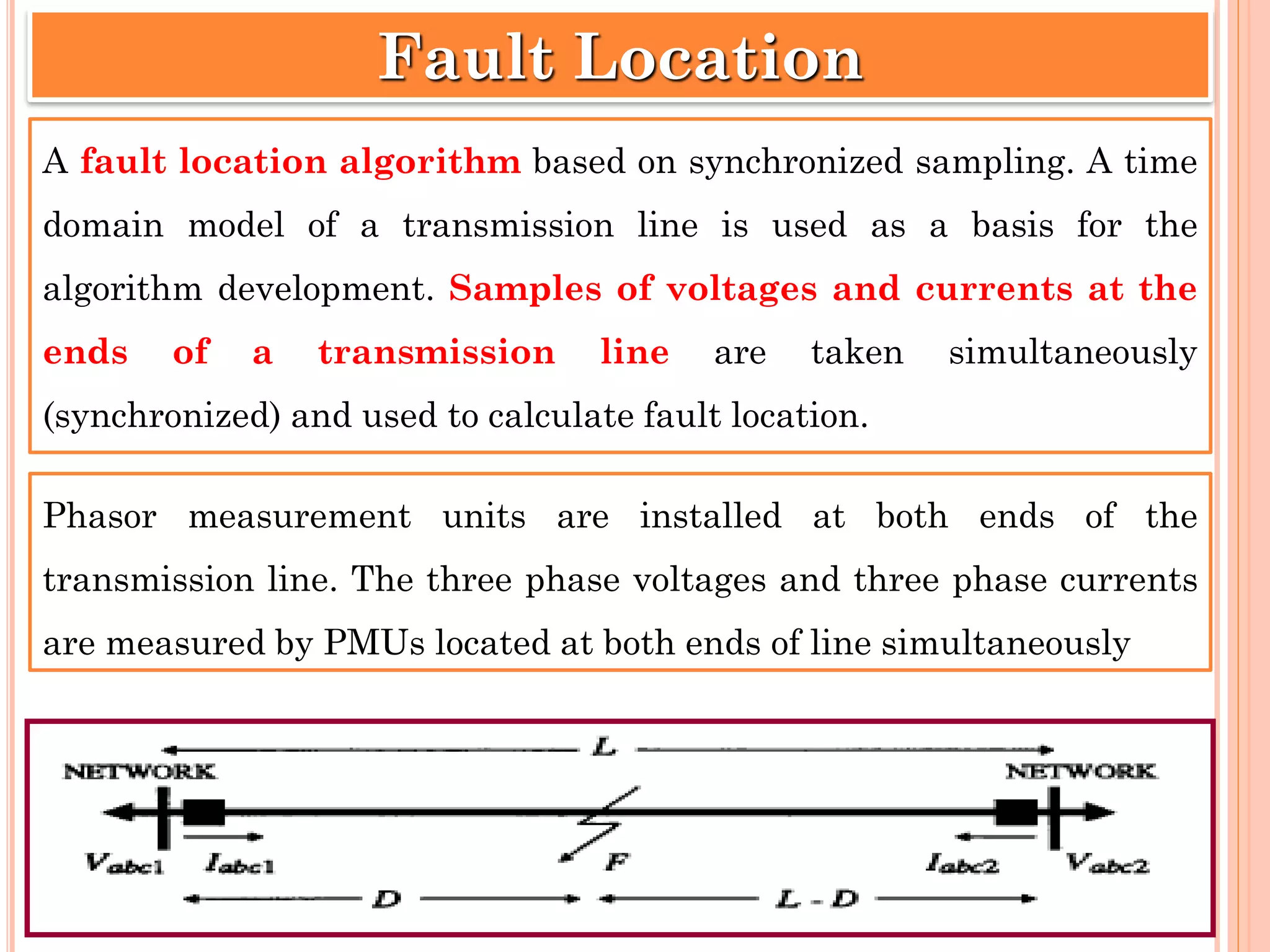
A fault locationalgorithm based on synchronized sampling. A time
domain model of a transmission line is used as a basis for the
algorithm development. Samples of voltages and currents at the
ends of a transmission line are taken simultaneously
(synchronized) and used to calculate fault location.
Fault Location
Phasor measurement units are installed at both ends of the
transmission line. The three phase voltages and three phase currents
are measured by PMUs located at both ends of line simultaneously
33.
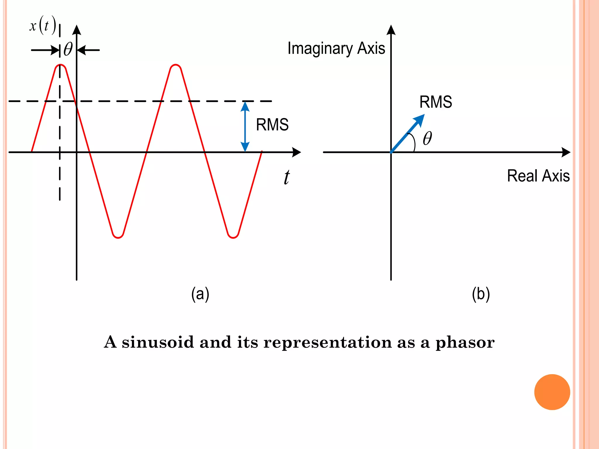
A puresinusoid quantity given by 𝑥 𝑡 = 𝑋 𝑚cos(𝜔𝑡 + 𝜃) and its
phasor representation 𝑋 = Τ𝑋 𝑚 2 𝑒 𝑗𝜃 = Τ𝑋 𝑚 2 𝑐𝑜𝑠𝜃 + 𝑗𝑠𝑖𝑛𝜃
are illustrated in Figure. The aim of phasor estimation technique
is just to acquire the phasor representation.
Samples of waveform data are collected over a data window which
is normally one period of the fundamental frequency of the power
system. In early days a sampling rate of 12 times a cycle (720 Hz
for the 60 Hz system) was commonly used. Much higher sampling
rates are currently used in commercial PMUs.
Phasor Measuremnet Techniques
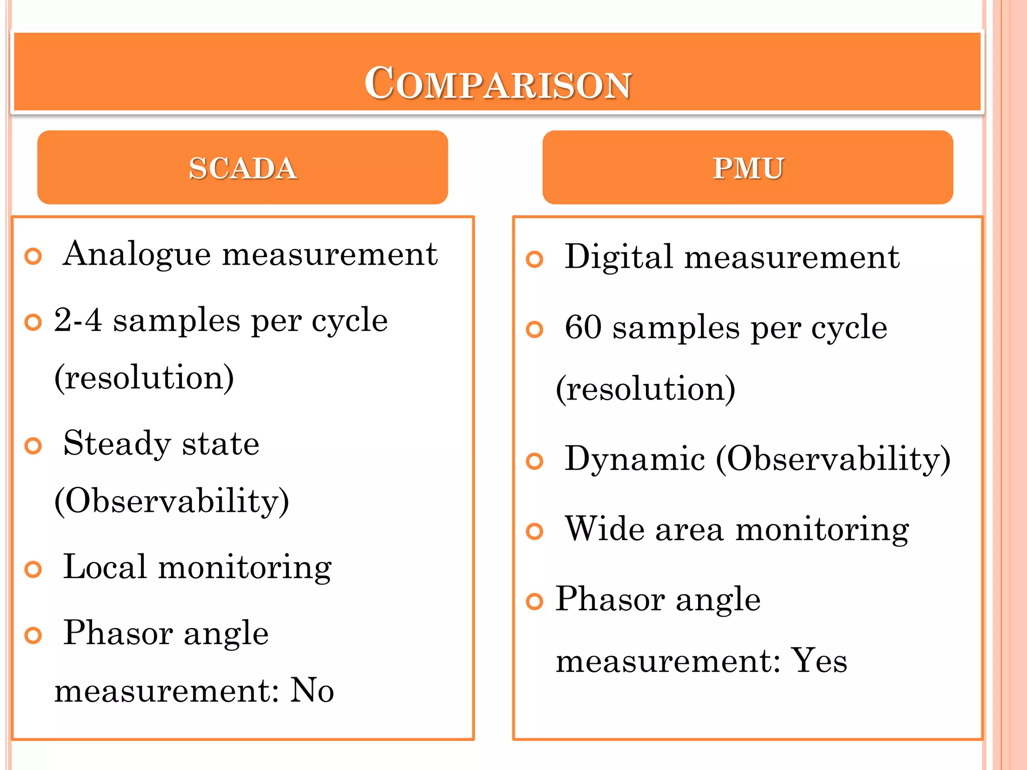
COMPARISON
Digital measurement
60 samples per cycle
(resolution)
Dynamic (Observability)
Wide area monitoring
Phasor angle
measurement: Yes
SCADA PMU
Analogue measurement
2-4 samples per cycle
(resolution)
Steady state
(Observability)
Local monitoring
Phasor angle
measurement: No
36.
REFERENCES
Phadke, A.G., & Thorp, J. S. (2006, October). History and
applications of phasor measurements. In 2006 IEEE PES Power
Systems Conference and Exposition (pp. 331-335). IEEE.
Tholomier, D., Kang, H., & Cvorovic, B. (2009, March). Phasor
measurement units: Functionality and applications. In 2009
Power Systems Conference (pp. 1-12). IEEE.
Phadke, A. G., & Tianshu, B. I. (2018). Phasor measurement
units, WAMS, and their applications in protection and control of
power systems. Journal of Modern Power Systems and Clean
Energy, 6(4), 619-629.
37.
QUESTIONS
How doesa Phasor Measurement Unit (PMU) work?
What are the main components of PMU? Explain
briefly with PMU Block Diagram.
What is use of PMU in Smart Grid?
Explain the application of PMU in power system.
What is synchrophasor?
What is phasor measurement techniques?