Download to read offline
![International Research Journal of Engineering and Technology (IRJET) e-ISSN: 2395-0056
Volume: 06 Issue: 03 | Mar 2019 www.irjet.net p-ISSN: 2395-0072
© 2019, IRJET | Impact Factor value: 7.211 | ISO 9001:2008 Certified Journal | Page 1442
with networks such as Wi-Fi, Ethernet makes it suitable to be
used in controlling and monitoring application.
III. LITERATURE SURVEY
The main problem identified is large amount of
power shortage is caused due to power theft. Power theft is
considered as a crime. Illegal connection can severely
overburden the grids and invite power wastages responsible
electricity user may suffer power problems .Manually it is
difficult to detect the theft of electricity. Power theft in
transmission lines is shown in fig 1.
Rakesh dwivodi, Ashwani kumar, Sandhya dubey
implement a theft detection method in 2015, but this system
uses power line communication method having drawback as
tampering area is not detected. And the other author G.Kate ,
R.Rana proposed a method of power theft automatic energy
meter reading having drawback such as If theft occur supply
cutoff from .EB Side and Record of billing within certain
period message from EB side. The other method proposed by
M.Jain , A.M.Karandiakr of detecting survey of power theft
technique using method SVM,ELM, ANN having
disadvantage such as Detection rate accuracy (%) is differ
from one algorithm.
The other method implemented in the year 2016 by
C.Dhendwal diksha Hyades Mayer Prof.Bala Kumkum
Survey on identify electricity theft using data mining
technique using method such as ANNK-Means clusteringal
algorithm. Fuzzy logic which having cons such as
implementation is very difficult .In the year 2016 Pratap
Jumale, Avinash Khaire, Harshada Jadhawar, Sneha Awathare,
Manisha Mali implemented a method of Survey: Electricity
Theft Detection Technique having drawback as Less Accuracy
and Installation problem. In the year 2017; M.K.Sangole,
Akshay Bhandane Nitin bhandane Giridhari balder
implement a power theft detection using gsm having problem
such as Automated smart meteringPower consumption is
monitered by mobile only it is not good at all times working.
Fig [1]: Power theft in transmission lines
In the year 2017; Muhammad saad Muhammad faraz
tariq proposed a method Theft detection based GSM Prepaid
electrical system having drawback such as complex design an
installation problem. Later in the year 2017 R.E.Ogu,
G.A.Chukwvdebe implement a method Development of cost
effective electricity theft detection & prevention system
based on IoT Technology but having serious drawback such
as Detects human tampering ,If robot is programmed to
tamper the meter this system is useless ,Passive IR sensor
detects human within 5m. Again in the year 2017 R.Giridhar
balakrishna, P.Yoganandha reddy M.L.N.Vital implement a
method IoT Based power theft detection having drawback
such as ESP Module is used but It sometimes cause too much
reliability problems Wifi codes takes lot of CPU power.
In 2017 Saurabh Singh,Krishna Yadav, Harjeet
Matharu,Prachi Singh, Anvita BirjeImplement a method of
power theft detectin using RF Technology having problem
such as Onetime installation cost and used for lifelong
Circuit implementation is simple. In 2018; L.Hinduja
B.Priyavardhana GSM based electricity theft using arduino
had some demerit such as No human interface Cost high to
implement ,Received theft tampering messages to mobile. To
overcome these problems in the electricity theft detection,
we used to implement our proposed method by find out the
tampering area and transmission loss and good installation
facility our proposed method will help to overcome these
types of problems in future. Survey of power theft all over
India is shown in fig 2.
Fig [2]: survey of electricity theft all over India
Rampant power theft at the low voltage consumer end is
a growing concern for the power distribution companies.
This paper proposes an effective method for detection of
power theft at low voltage consumer end. The proposed
method is designed to reliably detect hooking in service line
cable and bypassing of electric energy meter. In this method,
a low magnitude, high-frequency, non-interfering signal has
been injected into the power line.](https://image.slidesharecdn.com/irjet-v6i3272-190817091439/75/IRJET-Wireless-Electricity-Theft-Detection-using-Zigbee-2-2048.jpg)
![International Research Journal of Engineering and Technology (IRJET) e-ISSN: 2395-0056
Volume: 06 Issue: 03 | Mar 2019 www.irjet.net p-ISSN: 2395-0072
© 2019, IRJET | Impact Factor value: 7.211 | ISO 9001:2008 Certified Journal | Page 1443
IV. SOFTWARE DISCRIPTION
AVR studio is an Integrated and Development
Environment (IDE) by ATMEL for developing applications
based on 8-bit AVR microcontrollers. Prior to installation of
the AVR Studio you have to install the compiler Win AVR.
Wever, it is commonly accepted that the AVR stands for Alf
and Vegard's RISC and CISC processor. AVR is a family of
microcontrollers developed since 1996 by the Atmel
corporation, acquire by Microchip Technology in the year
2016.AVR was one of the first microcontroller families to use
on-chip flash memory for program storages, memory as
opposed to the one-time programmable ROM and RAM,
EPROM, or EEPROM used by other microcontrollers at the
time. AVR Library is a free Software
Atmel AVR microcontrollers. Together, avrbinutils, avr-gcc,
and avr-libc form the heart of the Free Software tool device
tool chain for the Atmel AVR microcontrollers.
Download the latest Atmel Studio installer, AVR
Studio, Atmel Studio. The web installer is a small file (<10
MB) and which will download specified components devices
as needed. The offline installer has every required
components embedded Atmel Studio can be run side-by-side
with older versions of Atmel Studio and AVR Studio. Un
installation of any previous versions is not required. Verify
the hardware and software requirements from the 'System
Requirements' section make sure your user has local
administrator privilege. Save all your work before starting.
The installation might prompt you to restart if required.
Disconnect all the USB Serial hardware devices,
Double-click the installer executable files and follow the
installation wizard once finished, the installer displays an
option to Start Atmel Studio after completion. If you choose
to open, then note that Atmel Studio will launches with
administrative privileges, and since the installer was either
launched as administrator or with elevated privileges, In the
Atmel Studio you may see an update notification next to the
Quick Launch the fields in the title bars.
Fig [3]: AVR Project window file
V. PROPOSED METHOD
TRANSMITTER SIDE
RECEIVER SIDE
A) ATMega8 Microcontroller
AVR Microcontroller was produced by the “Atmel”. The
Microcontroller includes the Harvard architectures that
works rapidly with the RISC processor the features of this
Microcontroller include different features like sleep modes,
internal oscillator and serial data communication, performs
the instructions in a single execution cycle faster and easier
mode. These Microcontrollers were very fast and they utilize
low power to work in different power saving modes and
operations. There are different configurations of AVR
microcontrollers are available to perform various operations
like 8-bit, 16-bit, and 32-bit and 64 bit.
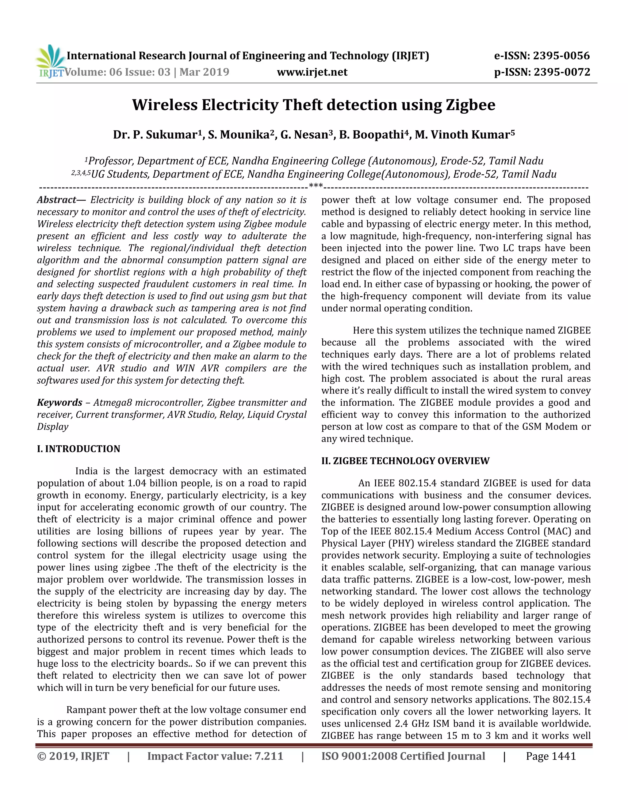
B) Current Transformer
The Current Transformer is a type of “instrumental
transformer” which is designed to produce an](https://image.slidesharecdn.com/irjet-v6i3272-190817091439/75/IRJET-Wireless-Electricity-Theft-Detection-using-Zigbee-3-2048.jpg)
![International Research Journal of Engineering and Technology (IRJET) e-ISSN: 2395-0056
Volume: 06 Issue: 03 | Mar 2019 www.irjet.net p-ISSN: 2395-0072
© 2019, IRJET | Impact Factor value: 7.211 | ISO 9001:2008 Certified Journal | Page 1444
alternating current AC in its secondary windings which is
proportional to the current being measured in its primary
coil. Current transformers are used extensively for measuring
current and power voltage and monitoring the operation of
the power grid.
Fig [4] current transformer
C) Relay
Relays are switches type that open and close circuits
electromechanically or electronically. Relays control one
electrical circuit by opening and closing the contacts in
another circuit. Relays are used in switching circuits by
giving a small signal to the coil inside it, when a signal is sent
into the coil.
D) Zigbee
ZigBee is an IEEE 802.15.4- standard specification suited
for high-level communication protocols used to create
personal area networks with small, low-power digital radios,
networks such as for home automation, medical devices data
collections, and other low-power consumption and low-
bandwidth needs, designed for small scale projects which is
shown in fig 2.
Fig [5]: ZIGBEE MODULE
E) Power supply
A power supply is an electrical device that
supplies electric power to the electrical loads. The main
functions of the power supply is to convert electric
current from the source, to the correct voltage, as electrical
power converters. Some power supplies are separated by
stand alone pieces of equipment, while others are built into
the load appliances that they power.
F) LCD
LCD (Liquid Crystal Display) screen is an
electronic display module and to find a wide range of
applications. A 16x2 Liquid crystal display is very basic
modules and is very commonly used in various devices and
circuits in electronics and electrical. A 16x2 LCD means it can
display 16 characters per line and there are 2 such lines and
displays messages.
G) Buzzer
A buzzer or beepers are an audio signalling devices in
electrical items, which may be
electrical, mechanical, electromechanical, or piezoelectric .
Typical uses of buzzers and beepers include alarm
devices, timers indicators, detectors.
H) PC
A personal computer is a multi-purpose computer whose
size shape, intelligence,, capabilities, and price make it
feasible for individual use. Personal computers are intended
to be operate directly by an end user, rather than by a
computer expert or technician
VI. METHODOLOGY
1) TRANSMITTERE SIDE
The proposed system deals with the idea of
developing a system that prevents electricity theft. Here a
microcontroller atmega8 is fixed in both transmitter side and
receiver side. In both transmitter and receiver side the zigbee
transmitter and receiver is fixed with the atmega8
microcontroller at input and output ports. A microcontroller
is used which acts as the central control unit of the system
which coordinates and controls all the input and output
devices. Transmitter part consisting of two current
transformers which iks connected in the load. Then
transformer is used to fix in the transmitter side to step down
the ac current source and rectified to 12V dc current source
,because all the zigbee and other devices in our project works
in the dc current source. The current transformer here acts as
the power sensor. The microcontroller ATmega8](https://image.slidesharecdn.com/irjet-v6i3272-190817091439/75/IRJET-Wireless-Electricity-Theft-Detection-using-Zigbee-4-2048.jpg)
![International Research Journal of Engineering and Technology (IRJET) e-ISSN: 2395-0056
Volume: 06 Issue: 03 | Mar 2019 www.irjet.net p-ISSN: 2395-0072
© 2019, IRJET | Impact Factor value: 7.211 | ISO 9001:2008 Certified Journal | Page 1445
continuously monitors the signal from the current
transformer. Incase of any extra load on the load side, there
will be a varying signal from current transformer, and the
controller is programmed in such a way that when the signal
from the current transformer goes beyond the threshold
value, the relay has to be shut down.When there is any
tapering or fraud connections occurred in our transmission
lines or energy meters or transformers the load resistance
may change automatically.
Fig [6]: Initial condition of LCD Display
2) RECEIVER SIDE
In the receiver section the atmega8 microcontroller is
fixed which is connected with the zigbee receiver and the
power supply. The power supply block is the one that
supplies power to the microcontroller ATmega8, zigbee
receiver and the liquid crystal display. The microcontroller
ATmega8 does the job of displaying the data that is received
from the zigbee receiver. If there is any tampering occurred
in the transmitter side, the zigbee transmitter transmits the
data to the zigbee receiver side, then the sensor senses the
output and displayed on the liquid crystal display and buzzer
and the pc which is already programmed and dumped on the
microcontroller. The parameters are viewed on the LCD, PC
and Buzzer. In the display if there is any load connected by us
initially the meter is no theft condition, if there is any
tampering occurred in our load side the transmission loss is
indicated on the LCD and it displays electricity theft at which
area or place in the line in the display.
Fig [7]: LCD Displaying for bypassing
V11. CONCLUSION
The new proposed system introduces a new technique of
detection of theft of electricity. The results under the no theft
condition and theft condition has proved that the embedded
system technique can be effectively used for the detection of
the theft of electricity in the Power system. By using this
technique electricity power theft in our home, industries,
factories are easily findout and calculated without any human
interface. The crime of stealing power may be brought to an
end and thereby a new bloom may be expected in the
economy of our motherland and also there will no wastage of
electricity and power in our nation.
VIII. FUTURE SCOPE
1. Automatic meter reading and billing in water management
system.
2. Notification via SMS or email of billing of any information
related to the power management systems.
3. Online billing systems should be link with this systems.
REFERENCES
1. Rakesh dwivodi, Ashwani kumar, Sandhya dubey
“Design and implementation of power theft
detection in automatic meter reading using power
line communication” IJEETC ; VOL-1; NO-2; July
2015.
2. G.Kate , R.Rana “ Zigbee monitoring theft
detection using automatic electricity meter
reading” ICESA ;2015.
3. M.Jain , A.M.Karandiakr “A survey of power theft
detection” IJIRCCE, VOL-4, Issue 1; Jan 2016.
4. C.Dhendwal diksha ,H.Yadev mayer, Prof.Bala
Kumkum “Survey on identify electricity theft
using data mining technique” IJIRCCE; VOL -4;
ISSUE 11-NOV 2016
5. Pratap Jumale,Avinash, Khaire,Harshada,
Jadhawar,Sneha ,Awathare,Manisha Mali “Survey
Electricity Theft Detection Technique” VOL. 8, NO.
2, February 2016, International Journal of
Computer Engineering and Information
Technology.
6. M.K.Sangole, Akshay Bhandane, Nitin bhandane
,Giridhari balder “Smart Energy Metering and
Power Theft Control using Arduino &gsm” 2017
2nd International Conference for Convergence in
Technology (I2CT).
7. Visalatchi , kamal sandeep, “Smart Energy
Metering and Power Theft Control using Arduino
&gsm” 2017 2nd International Conference for
Convergence in Technology (I2CT)](https://image.slidesharecdn.com/irjet-v6i3272-190817091439/75/IRJET-Wireless-Electricity-Theft-Detection-using-Zigbee-5-2048.jpg)

This document describes a wireless electricity theft detection system using Zigbee technology. The system consists of a transmitter side and receiver side connected by Zigbee modules. On the transmitter side, current transformers are connected to the load and monitor the current. If theft is detected, based on abnormal current readings, a signal is sent via the Zigbee transmitter to the receiver. On the receiver side, the signal is received by the Zigbee receiver and relay and buzzer are activated to alert the user of theft. The system is designed to overcome issues with previous wired techniques by enabling wireless monitoring and detection of theft as well as identifying tampered areas. It aims to help reduce electricity losses due to theft.