Downloaded 1,694 times


This document discusses various methods of cooling power transformers. It describes air natural cooling and air blast cooling for smaller dry type transformers. For larger oil immersed transformers, it outlines oil natural, oil natural air forced, and oil natural water forced cooling. More advanced methods like oil forced air forced and oil forced water forced cooling are highlighted. The document also briefly introduces nitrogen cooling for high temperature superconducting transformers. It concludes by noting different cooling applications based on transformer size and type.
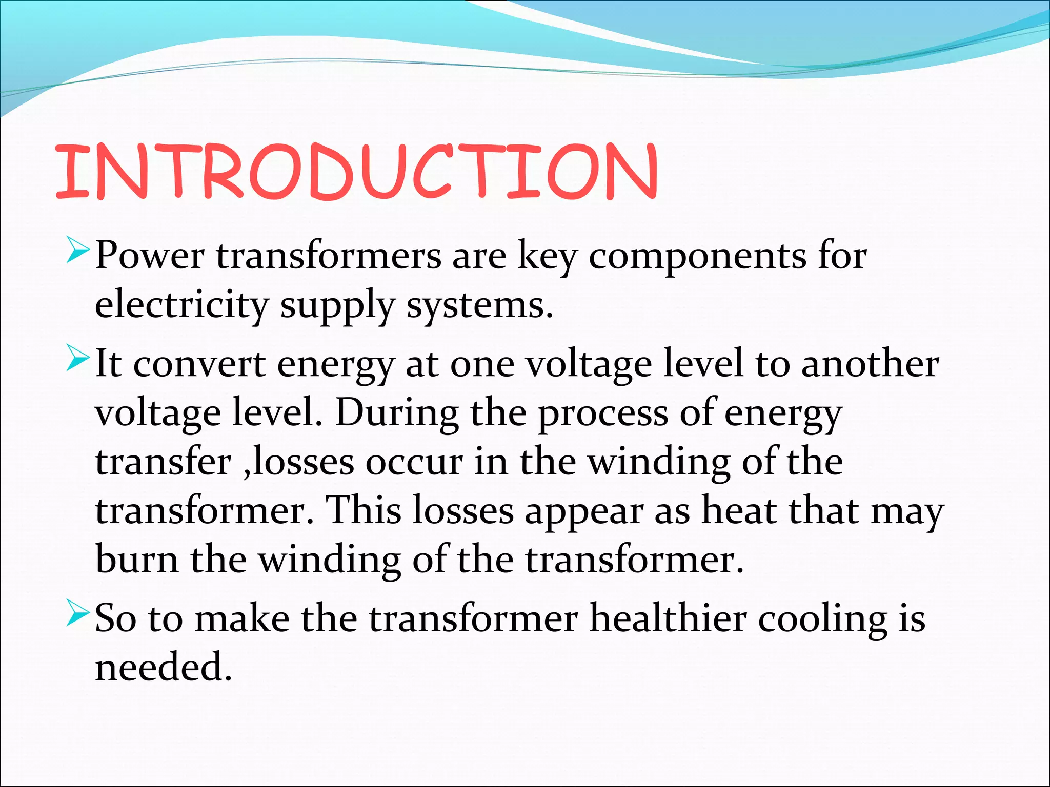
Introduction to power transformers and the need for cooling in energy transfer.
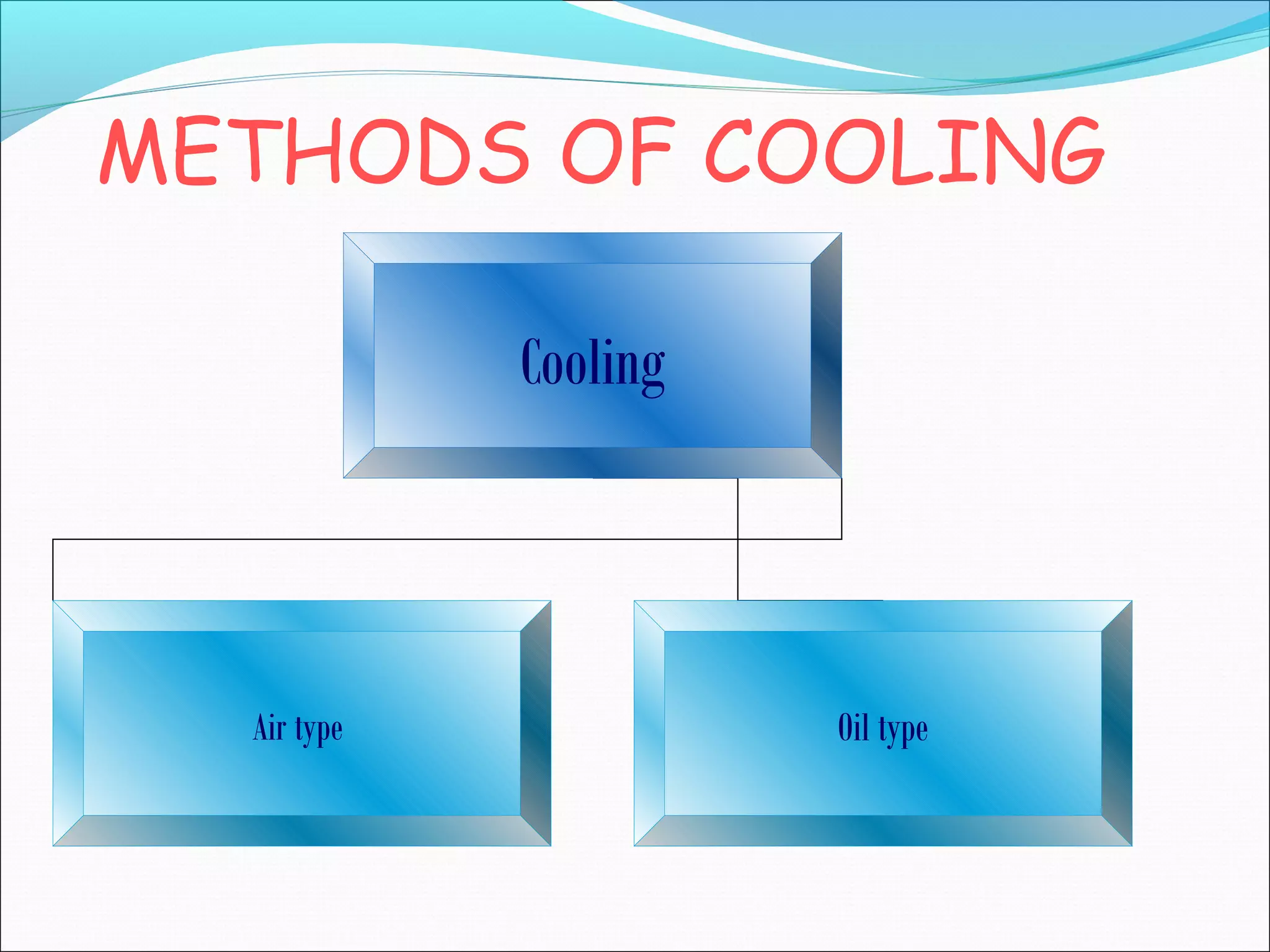
Introduction to types of cooling methods: air type and oil type cooling systems.
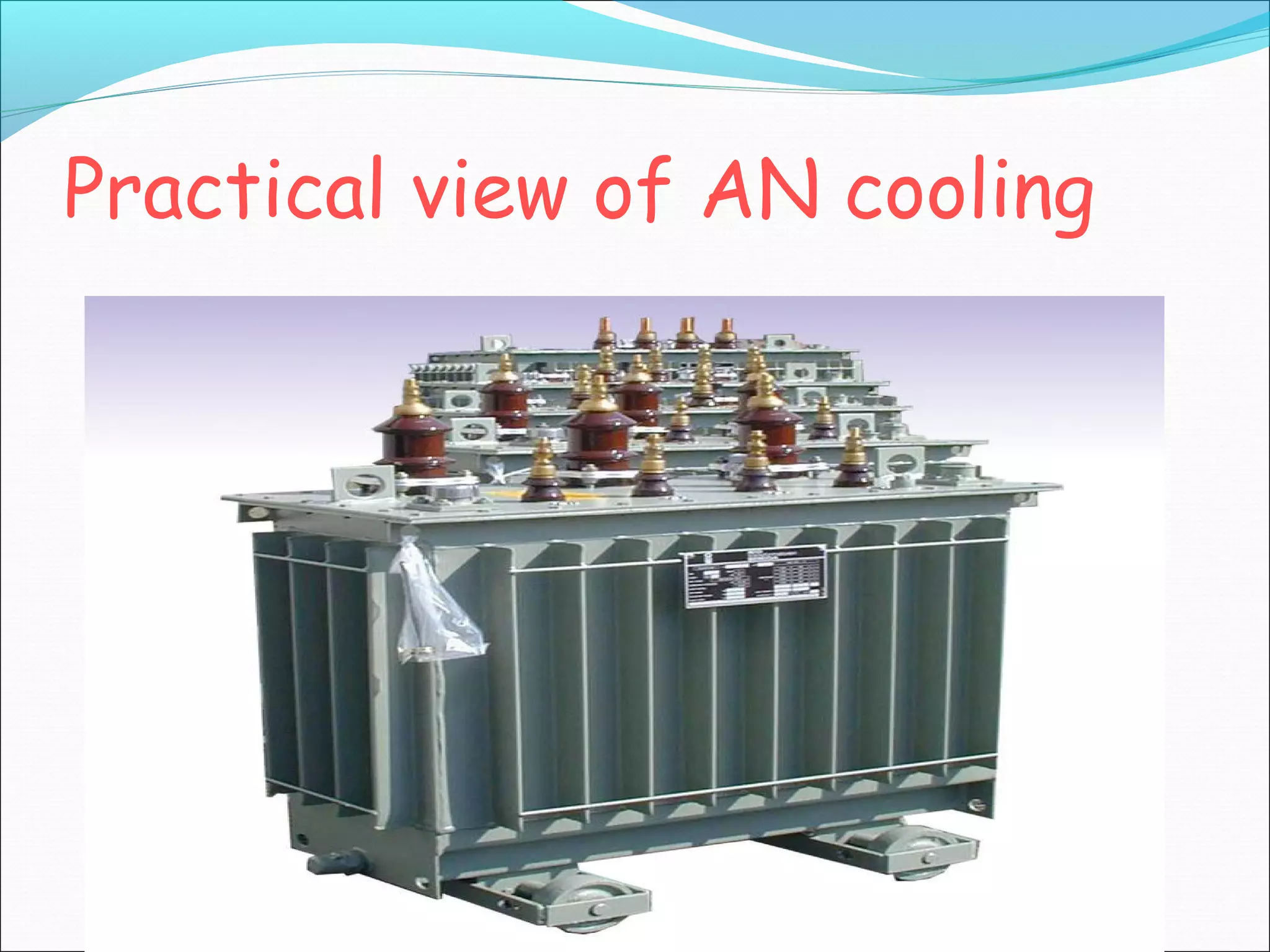
Air natural cooling for smaller transformers and air blast cooling for dry type transformers, including disadvantages.
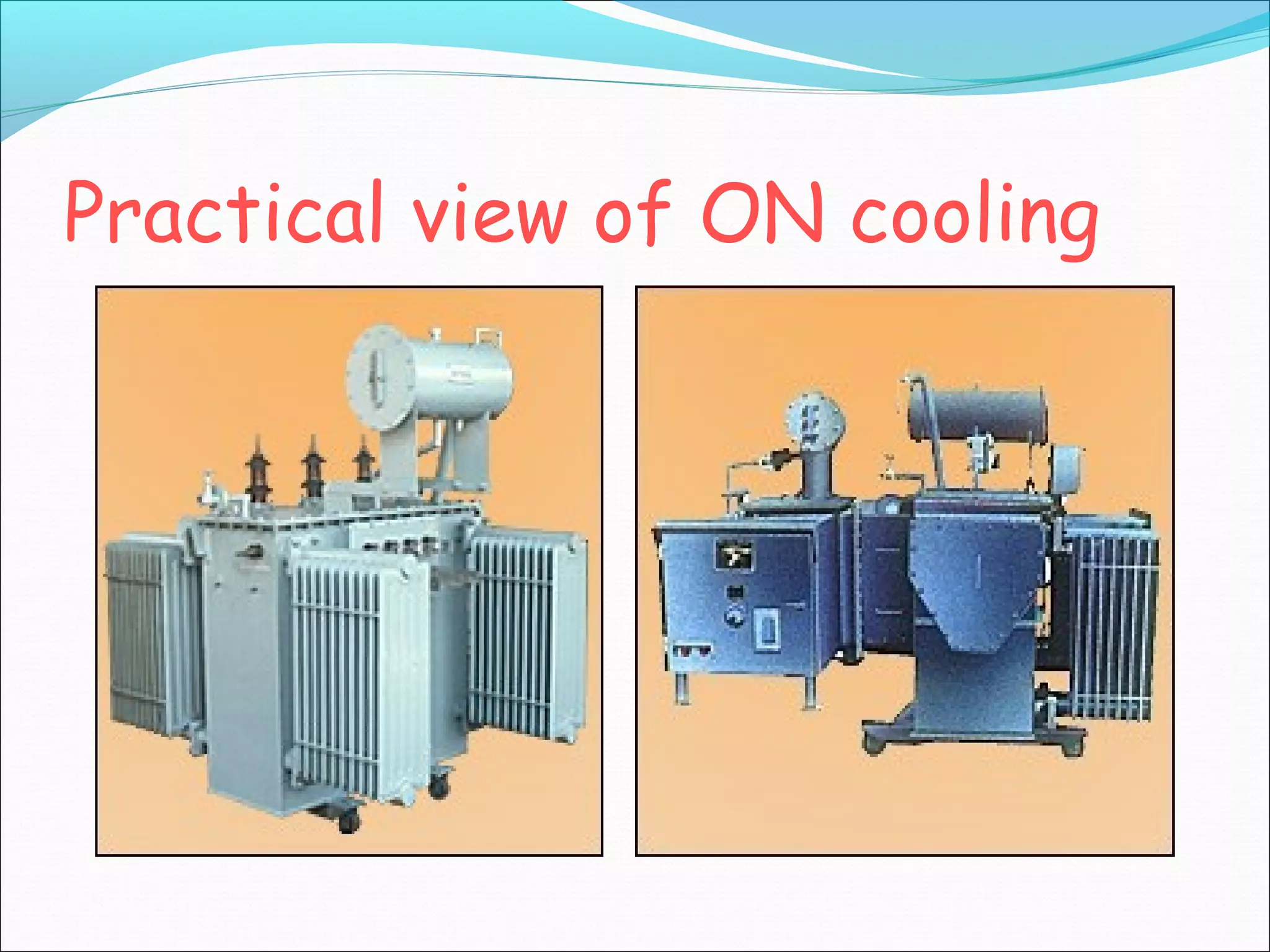
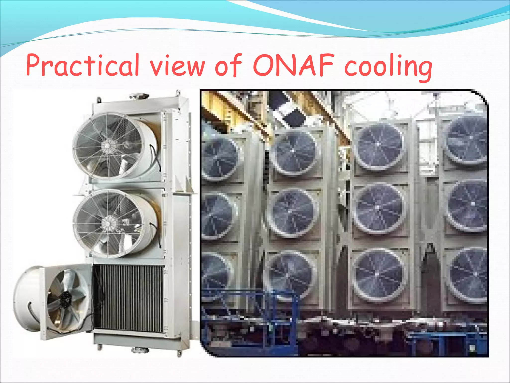
Detailed overview of oil natural cooling methods, including ON, ONAF, ONWF, OFAN, and OFAF, explaining their processes and applications.
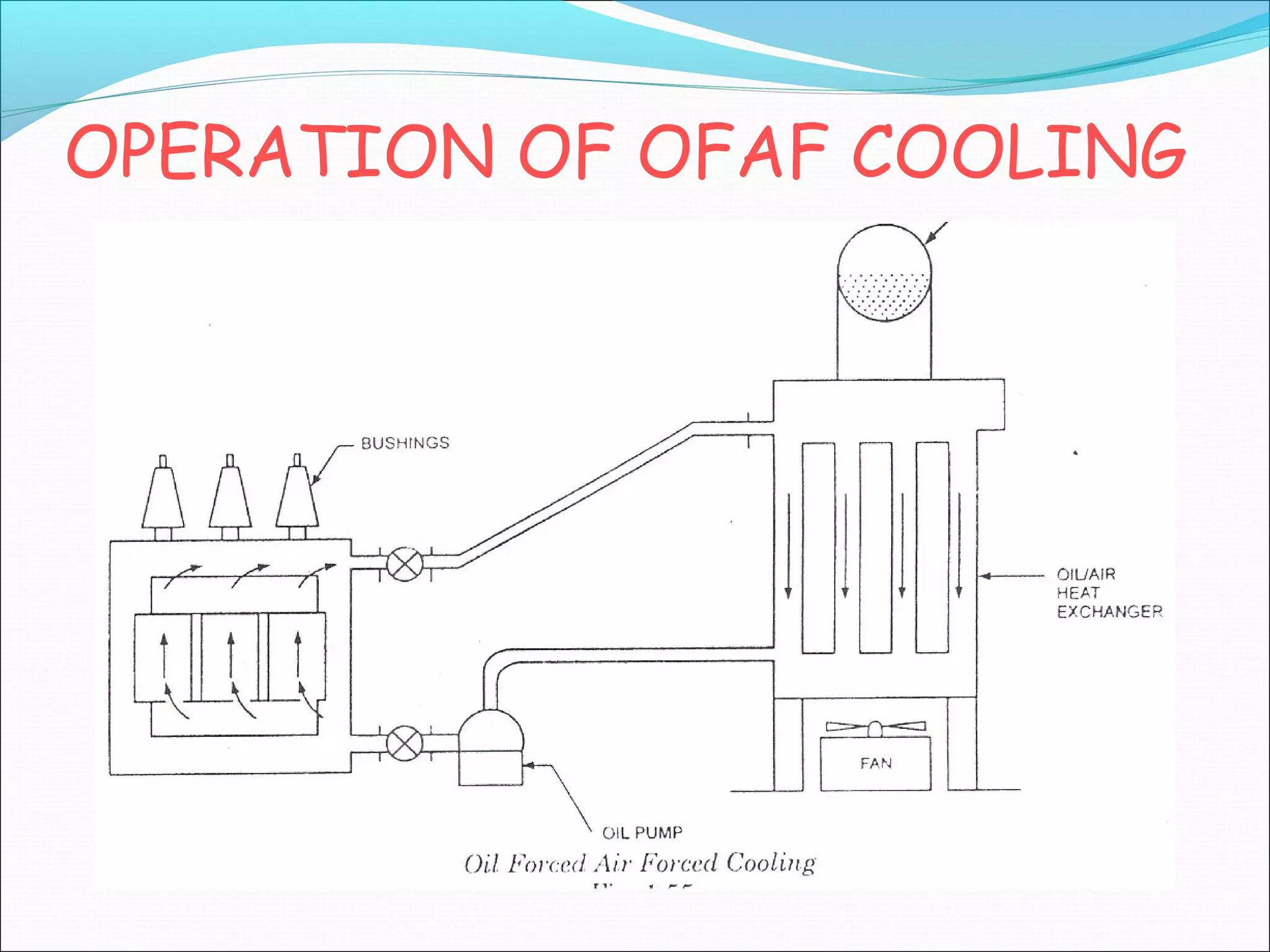
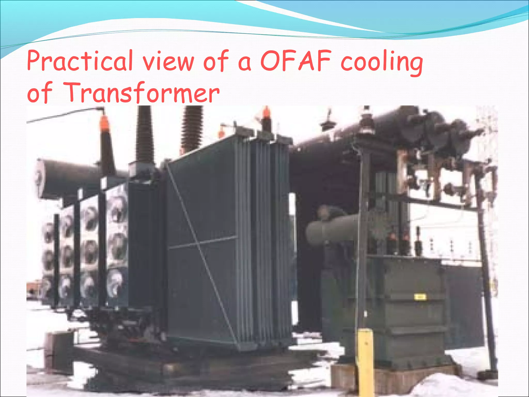
Operation detail and practical application of OFAF and OFWF cooling methods, ensuring efficient heat exchange.
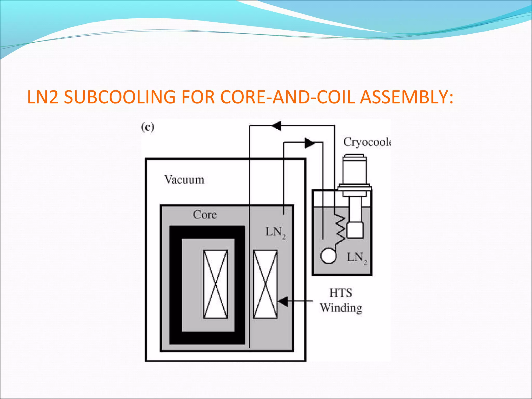
Nitrogen cooling system for HTS transformers, involving subcooled liquid nitrogen as a heat transfer medium.
Advantages of modern cooling techniques including lower maintenance costs and better efficiency.
Specific applications of various cooling methods based on transformer ratings and settings.
Conclusion on the necessity of cooling systems in transformers and other electrical equipment for improved efficiency.