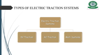
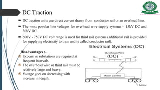
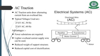
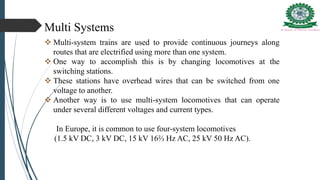
Seminar
on
Electric Traction System
Presented by :- Dipak Meher
7th Semester, 1301304064
Electrical Engineering
Under the guidance of : Prof. Ajoya Ku Pradhan
HOD
Dept. of Electrical Engineering
CONTENTS
 INTRODUCTION
 WHY ELECTRIC TRACTION SYSTEM???
 TYPES OF ELECTRIC TRACTION
 TYPE OF TRACK ELECTRIFICATION
 SINGLE CATENARY CONSTRUCTION
 SYSTEMS OF TRACK ELECTRIFICATION
 MAJOR COMPONENTS
 COMPONENTS OF AN A.C LOCOMOTIVE
 CONCLUSION
 REFERENCES
Introduction
 The process of moving any vehicle is called traction . If the electric
energy is use in this process is called electric traction.
 Classified broadly into groups namely:
 Non-Electric traction system/Mechanical traction
system:-
Traction system which do not involve the use of electricity such
as steam engine drive, IC engine drive etc.
 Electric traction system :-
The system which use electrical power for traction system i.e. for
railways, trams, trolleys, etc. is called electrical traction.
WHY ELECTRIC TRACTION SYSTEM ???
 Cheapness : Low operation cost
 Cleanliness: Smoke and gas free
 Maintenance cost : 50% less than other steam engines
 Starting time and speed: Without loss of time.
 High starting torque : Uses of D.C & A.C series motor- very high starting torque.
 Braking : Regenerative breaking is used which feeds back energy.
 Saving in high grade coal : Saving of non-renewable energy source.
TYPES OF ELECTRIC TRACTION SYSTEMS
DC Traction
 DC traction units use direct current drawn from conductor rail or an overhead line.
 The most popular line voltages for overhead wire supply systems – 15kV DC and
30kV DC.
 600V - 750V DC volt range is used for third rail systems (additional rail is provided
for supplying electricity to train and is called conductor rail).
Disadvantages :-
 Expensive substations are required at
frequent intervals.
 The overhead wire or third rail must be
relatively large and heavy.
 Voltage goes on decreasing with
increase in length.
AC Traction
 AC Traction units draw alternating
current from an overhead line.
 Typical Voltages Used are:-
25 kV AC, 50 Hz
25 kV AC, 60 Hz
Advantages :-
 Fewer substations are required.
 Lighter overhead current supply wire
can be used.
 Reduced weight of support structure.
 Reduced capital cost of electrification.
Multi Systems
 Multi-system trains are used to provide continuous journeys along
routes that are electrified using more than one system.
 One way to accomplish this is by changing locomotives at the
switching stations.
 These stations have overhead wires that can be switched from one
voltage to another.
 Another way is to use multi-system locomotives that can operate
under several different voltages and current types.
In Europe, it is common to use four-system locomotives
(1.5 kV DC, 3 kV DC, 15 kV 16⅔ Hz AC, 25 kV 50 Hz AC).
System of Track Electrification
 Trolley wire or contact wire – suspended with minimum of sag so that
contact between the trolley wire and current collector can be
maintained at higher speeds.
 This wire is supported by another wire known as catenary.
 Two different types of Catenary construction can be used
 Single Catenary
 Compound Catenary
Type of Track Electrification
• Single Catenary
Construction
• Compound Catenary
Construction
 Provided for speeds up to 120kmph.
 Span of catenary wire 45-90 m and
sag of 1-2m.
 Relatively Cheaper
 Less Maintenance
 Suitable where traffic is denser more
and operating speeds are low.
 Provided for speeds ranges 190-
224kmph.
 Additional wire called intermediate
wire is used to increase current
carrying capacity i.e., to have
increased traffic density.
Single Catenary Construction
Types of current collector
Bow Collector- A bow collector is
one of the three main devices used on
tramcars to transfer electric current
from the wires above to the tram
below. It has now been largely
replaced by the pantograph.
Pantograph Collector- Main function
is to maintain the link between
overhead contact wire and power
circuit of the locomotive at varying
speeds in different climate and wind
conditions.
MAJOR COMPONENTS
1-TRACTION SUBSTATION 2-OVERHEAD WIRING
3-CURRENT COLLECTOR 4-TRACK
5-TRACTION SYSTEM (VEHICLE)
COMPONENTS OF AN A.C LOCOMOTIVE
Parts Of Electric Locomotive
TRANSFORMER
 The line voltage has to be stepped
down before use on the train.
 Traction Transformers for trains and
railway stock transform the
overhead contact line voltage, which
ranges mainly from 15 kV or 25 kV
to voltages suitable for traction
converters (0.7 kV and 1.5 kV)
 Normally transformers used are of
rating 5600 kVA to 7200 kVA.
RECTIFIER
 A rectifier consist of thyristors and
diodes which is used to convert AC
to DC.
 Instead of conventional bridge
rectifiers thyristors are used.
 A modern locomotive usually have
at least two “Main Rectifier”.
Inverter
 The inverters are used for converting DC power from a fixed voltage
DC supply into an AC output voltage of variable frequency and fixed
or variable output AC voltage.
DC Link
 Used on modern electronic power systems between the single phase
rectifier and the 3-phase inverter.
 It is easier to convert the single phase AC from the overhead line to
the 3-phase required for the motors by rectifying it to DC and then
inverting the DC to 3-phase AC.
Train Lighting/Air Conditioning(TL/AC)
 Axel-driven generators are used to store batteries that power light ,
fans and electrical fittings.
 For powering air-conditioning equipment, an inverter was used to
convert the DC output of a set of batteries to 415V AC.
 Older coaches use banks of 24V batteries while 110V in newer
coaches.
 In Many air-conditioned coaches, a 'mid-on generator' (MOG) is
used.
TRACTION MOTORS
 D.C Series Motors- Develops high torque at low speeds and low
torque at high speed, exact requirement of the traction units.
 Torque is independent of the line voltage and thus unaffected by
the variations in the line voltage.
Where, P is no of poles,
φ is flux per pole,
Z is no. of conductors,
A is no. of parallel paths
 Single phase A.C Series Motors- Starting torque is lower than dc
series motor due to poor power factor at starting.
 Maximum operating voltage is limited to 400 Volts.
Torque=
𝑃𝑚𝑒𝑐ℎ
𝞈𝑚
=
𝐸𝑏𝑎𝑐∗𝐼𝑎
2∗𝞹∗𝑁𝑎𝑐
Where, Eac = EMF of AC motor
Ia =Armature Current
Nac=Speed of rotor
 Three Phase Induction Motors- Provides constant speed
operation, developing low starting torque drawing high starting
current and complicated control networks makes it unsuitable for
electric traction work.
 Automatic regeneration is the main advantage in electric traction
with this motor.
s= slip of Induction motor
ELECTRICAL BRAKING
We can say that it is the process of reducing speed of any rotating
machine. Classified into three categories-
1.Plugging 2.Rheostatic braking 3.Regenerative braking
1)Plugging- Plugging is applied
by changing phase sequence of
synchronous or induction
motors. The main disadvantage
of this method is that here
power is wasted.
2)Rheostatic breaking-Connection
are made changed from power
configuration to brake
configuration and resistor are
inserted in motor circuit.
3) Regenerative braking- Motors
become generators and feed resulting
current back into supply system.
Conclusion
 No single motor is ideal for traction purposes. But; DC series motors
are most suitable for this work
 Power electronics has been restored to in a major way for conversion
and control operations.
 Different type of braking were discussed out of which regenerative is
most efficient.
 Though electric locomotives are more efficient than steam and diesel
locomotives.
References
 Electric Traction for Railway Trains ; Mc Graw -Hill Book Company.
 Railway Traction. The Principles of Mechanical and Electrical
Railway Traction , Andrews, H.I. (1986) Ed: Elsevier.
 Handbook of Railway Dynamics. Ed. Taylor & Francis Group.
London, Reino Unido.
 Modern Railway Track. Ed. Delft University of Technology. Delft,
Holanda
THANK YOU

Electric traction

  • 1.
    Seminar on Electric Traction System Presentedby :- Dipak Meher 7th Semester, 1301304064 Electrical Engineering Under the guidance of : Prof. Ajoya Ku Pradhan HOD Dept. of Electrical Engineering
  • 2.
    CONTENTS  INTRODUCTION  WHYELECTRIC TRACTION SYSTEM???  TYPES OF ELECTRIC TRACTION  TYPE OF TRACK ELECTRIFICATION  SINGLE CATENARY CONSTRUCTION  SYSTEMS OF TRACK ELECTRIFICATION  MAJOR COMPONENTS  COMPONENTS OF AN A.C LOCOMOTIVE  CONCLUSION  REFERENCES
  • 3.
    Introduction  The processof moving any vehicle is called traction . If the electric energy is use in this process is called electric traction.  Classified broadly into groups namely:  Non-Electric traction system/Mechanical traction system:- Traction system which do not involve the use of electricity such as steam engine drive, IC engine drive etc.  Electric traction system :- The system which use electrical power for traction system i.e. for railways, trams, trolleys, etc. is called electrical traction.
  • 4.
    WHY ELECTRIC TRACTIONSYSTEM ???  Cheapness : Low operation cost  Cleanliness: Smoke and gas free  Maintenance cost : 50% less than other steam engines  Starting time and speed: Without loss of time.  High starting torque : Uses of D.C & A.C series motor- very high starting torque.  Braking : Regenerative breaking is used which feeds back energy.  Saving in high grade coal : Saving of non-renewable energy source.
  • 5.
    TYPES OF ELECTRICTRACTION SYSTEMS
  • 6.
    DC Traction  DCtraction units use direct current drawn from conductor rail or an overhead line.  The most popular line voltages for overhead wire supply systems – 15kV DC and 30kV DC.  600V - 750V DC volt range is used for third rail systems (additional rail is provided for supplying electricity to train and is called conductor rail). Disadvantages :-  Expensive substations are required at frequent intervals.  The overhead wire or third rail must be relatively large and heavy.  Voltage goes on decreasing with increase in length.
  • 7.
    AC Traction  ACTraction units draw alternating current from an overhead line.  Typical Voltages Used are:- 25 kV AC, 50 Hz 25 kV AC, 60 Hz Advantages :-  Fewer substations are required.  Lighter overhead current supply wire can be used.  Reduced weight of support structure.  Reduced capital cost of electrification.
  • 8.
    Multi Systems  Multi-systemtrains are used to provide continuous journeys along routes that are electrified using more than one system.  One way to accomplish this is by changing locomotives at the switching stations.  These stations have overhead wires that can be switched from one voltage to another.  Another way is to use multi-system locomotives that can operate under several different voltages and current types. In Europe, it is common to use four-system locomotives (1.5 kV DC, 3 kV DC, 15 kV 16⅔ Hz AC, 25 kV 50 Hz AC).
  • 9.
    System of TrackElectrification  Trolley wire or contact wire – suspended with minimum of sag so that contact between the trolley wire and current collector can be maintained at higher speeds.  This wire is supported by another wire known as catenary.  Two different types of Catenary construction can be used  Single Catenary  Compound Catenary
  • 10.
    Type of TrackElectrification • Single Catenary Construction • Compound Catenary Construction  Provided for speeds up to 120kmph.  Span of catenary wire 45-90 m and sag of 1-2m.  Relatively Cheaper  Less Maintenance  Suitable where traffic is denser more and operating speeds are low.  Provided for speeds ranges 190- 224kmph.  Additional wire called intermediate wire is used to increase current carrying capacity i.e., to have increased traffic density.
  • 11.
  • 12.
    Types of currentcollector Bow Collector- A bow collector is one of the three main devices used on tramcars to transfer electric current from the wires above to the tram below. It has now been largely replaced by the pantograph. Pantograph Collector- Main function is to maintain the link between overhead contact wire and power circuit of the locomotive at varying speeds in different climate and wind conditions.
  • 13.
    MAJOR COMPONENTS 1-TRACTION SUBSTATION2-OVERHEAD WIRING 3-CURRENT COLLECTOR 4-TRACK 5-TRACTION SYSTEM (VEHICLE)
  • 14.
    COMPONENTS OF ANA.C LOCOMOTIVE
  • 15.
    Parts Of ElectricLocomotive TRANSFORMER  The line voltage has to be stepped down before use on the train.  Traction Transformers for trains and railway stock transform the overhead contact line voltage, which ranges mainly from 15 kV or 25 kV to voltages suitable for traction converters (0.7 kV and 1.5 kV)  Normally transformers used are of rating 5600 kVA to 7200 kVA.
  • 16.
    RECTIFIER  A rectifierconsist of thyristors and diodes which is used to convert AC to DC.  Instead of conventional bridge rectifiers thyristors are used.  A modern locomotive usually have at least two “Main Rectifier”.
  • 17.
    Inverter  The invertersare used for converting DC power from a fixed voltage DC supply into an AC output voltage of variable frequency and fixed or variable output AC voltage.
  • 18.
    DC Link  Usedon modern electronic power systems between the single phase rectifier and the 3-phase inverter.  It is easier to convert the single phase AC from the overhead line to the 3-phase required for the motors by rectifying it to DC and then inverting the DC to 3-phase AC.
  • 19.
    Train Lighting/Air Conditioning(TL/AC) Axel-driven generators are used to store batteries that power light , fans and electrical fittings.  For powering air-conditioning equipment, an inverter was used to convert the DC output of a set of batteries to 415V AC.  Older coaches use banks of 24V batteries while 110V in newer coaches.  In Many air-conditioned coaches, a 'mid-on generator' (MOG) is used.
  • 20.
    TRACTION MOTORS  D.CSeries Motors- Develops high torque at low speeds and low torque at high speed, exact requirement of the traction units.  Torque is independent of the line voltage and thus unaffected by the variations in the line voltage. Where, P is no of poles, φ is flux per pole, Z is no. of conductors, A is no. of parallel paths
  • 21.
     Single phaseA.C Series Motors- Starting torque is lower than dc series motor due to poor power factor at starting.  Maximum operating voltage is limited to 400 Volts. Torque= 𝑃𝑚𝑒𝑐ℎ 𝞈𝑚 = 𝐸𝑏𝑎𝑐∗𝐼𝑎 2∗𝞹∗𝑁𝑎𝑐 Where, Eac = EMF of AC motor Ia =Armature Current Nac=Speed of rotor
  • 22.
     Three PhaseInduction Motors- Provides constant speed operation, developing low starting torque drawing high starting current and complicated control networks makes it unsuitable for electric traction work.  Automatic regeneration is the main advantage in electric traction with this motor. s= slip of Induction motor
  • 23.
    ELECTRICAL BRAKING We cansay that it is the process of reducing speed of any rotating machine. Classified into three categories- 1.Plugging 2.Rheostatic braking 3.Regenerative braking 1)Plugging- Plugging is applied by changing phase sequence of synchronous or induction motors. The main disadvantage of this method is that here power is wasted.
  • 24.
    2)Rheostatic breaking-Connection are madechanged from power configuration to brake configuration and resistor are inserted in motor circuit. 3) Regenerative braking- Motors become generators and feed resulting current back into supply system.
  • 25.
    Conclusion  No singlemotor is ideal for traction purposes. But; DC series motors are most suitable for this work  Power electronics has been restored to in a major way for conversion and control operations.  Different type of braking were discussed out of which regenerative is most efficient.  Though electric locomotives are more efficient than steam and diesel locomotives.
  • 26.
    References  Electric Tractionfor Railway Trains ; Mc Graw -Hill Book Company.  Railway Traction. The Principles of Mechanical and Electrical Railway Traction , Andrews, H.I. (1986) Ed: Elsevier.  Handbook of Railway Dynamics. Ed. Taylor & Francis Group. London, Reino Unido.  Modern Railway Track. Ed. Delft University of Technology. Delft, Holanda
  • 27.