Downloaded 1,768 times
![Space Vector Modulation
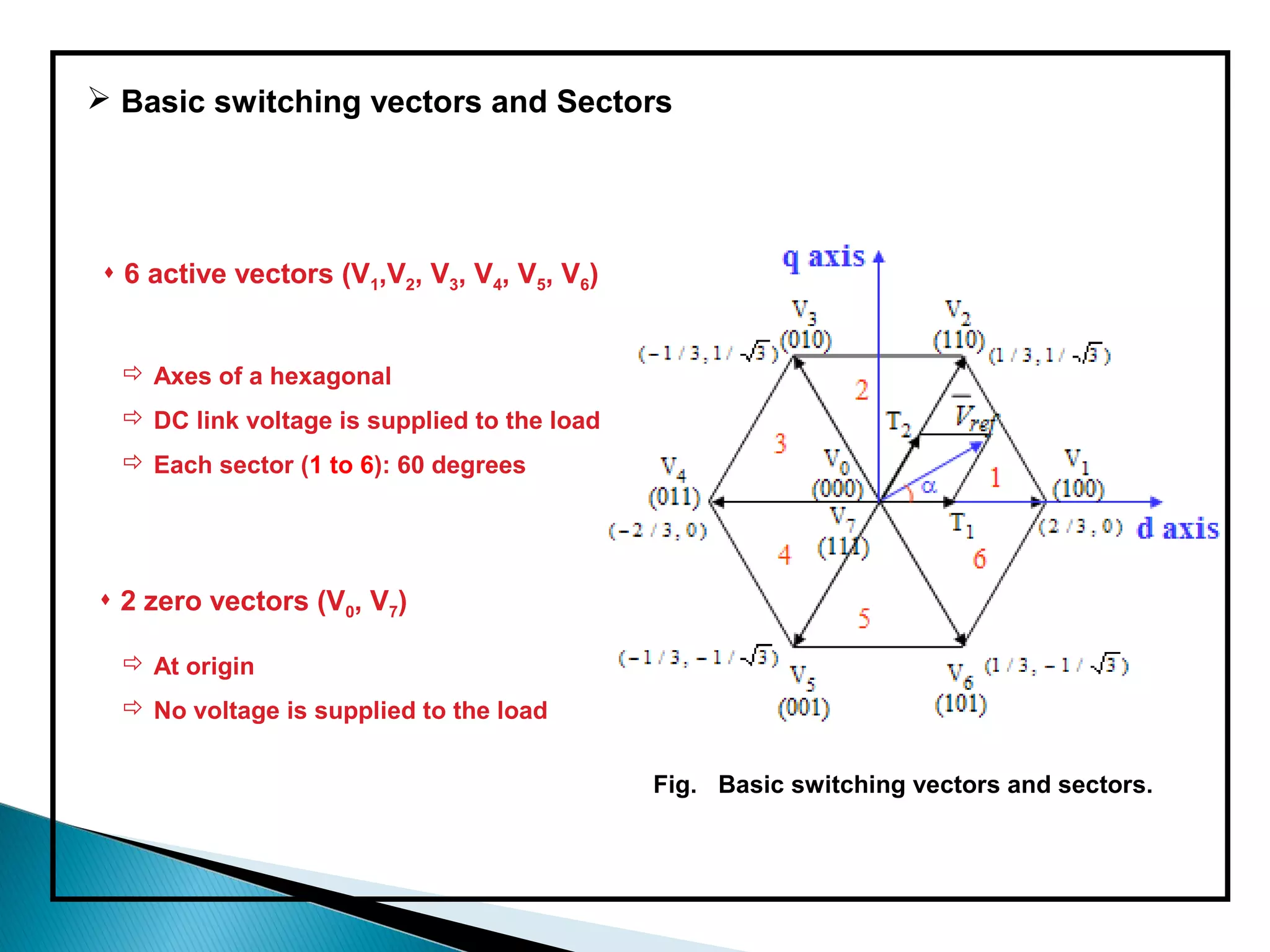
Sector 2
[010] V3 [110] V2
(1/√3)Vdc
Sector 3 Sector 1
[100] V1
[011] V4
(2/3)Vdc
Sector 4 2
(
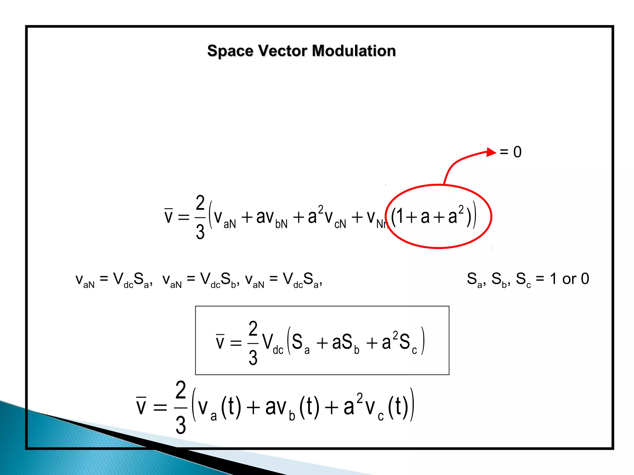
v = Vdc S a + aS b + a 2 S c
3
) Sector 6
[001] V5 Sector 5 [101] V6](https://image.slidesharecdn.com/svpwmpresentationsoumyaranjanpradhan-121126042858-phpapp01/75/Svpwm-18-2048.jpg)
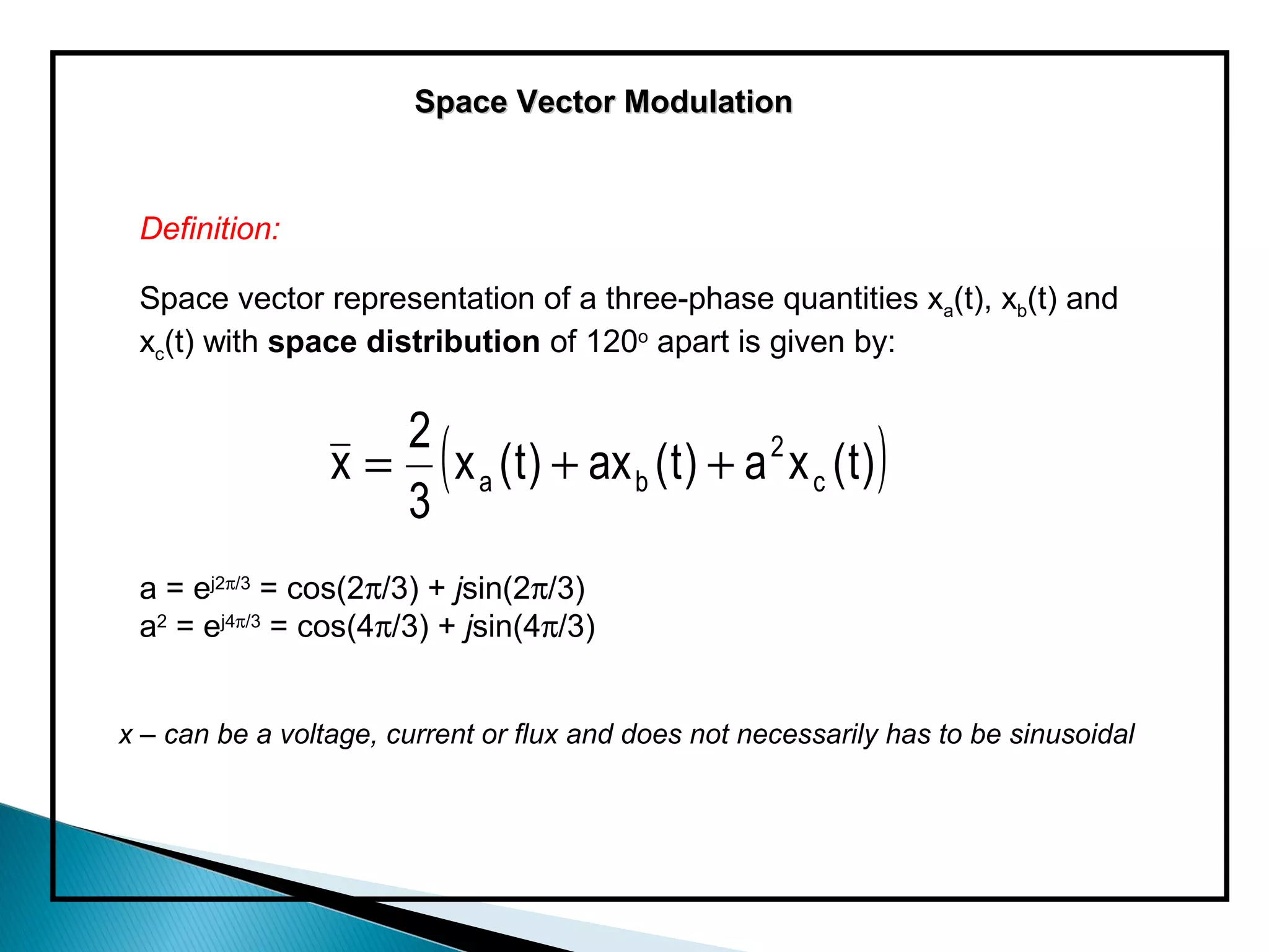
![Conversion from 3 phases to 2 phases :
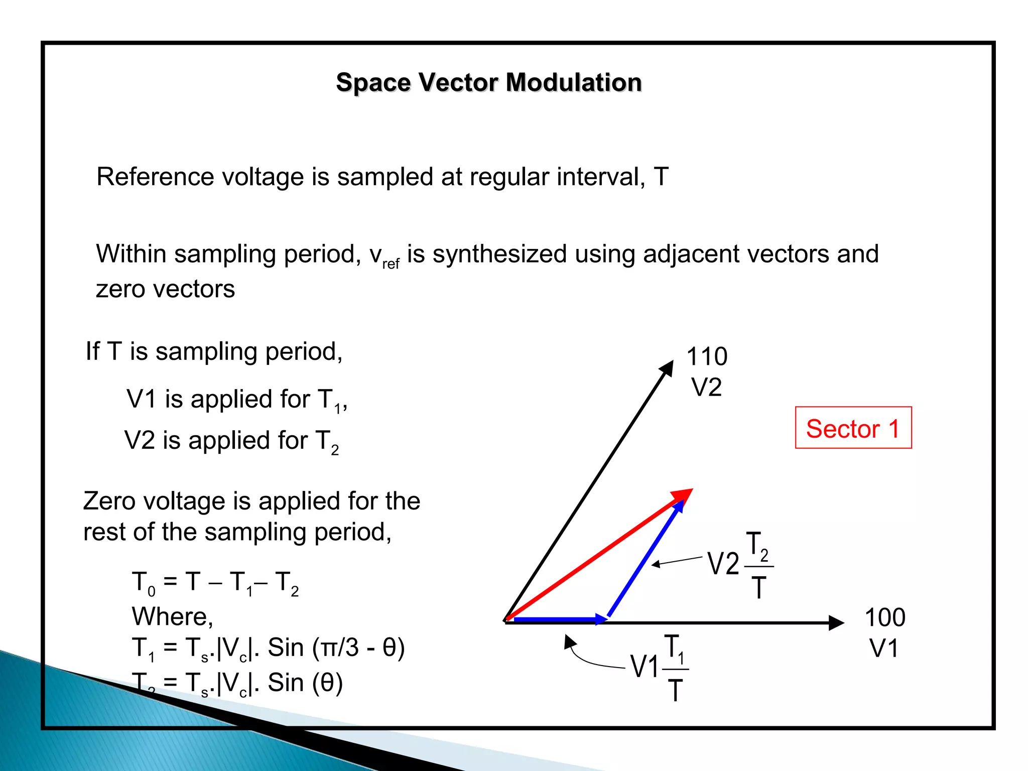
For Sector 1,
Three-phase line modulating signals (VC)abc = [VCaVCbVCc]T
can be represented by the represented by the complex vector
VC = [VC]αβ = [VCaVCb]T
by means of the following transformation:
VC α = 2/3 . [vCa - 0.5(vCb + vCc )]
VC β = √3/3 . (vCb - vCc)](https://image.slidesharecdn.com/svpwmpresentationsoumyaranjanpradhan-121126042858-phpapp01/75/Svpwm-19-2048.jpg)
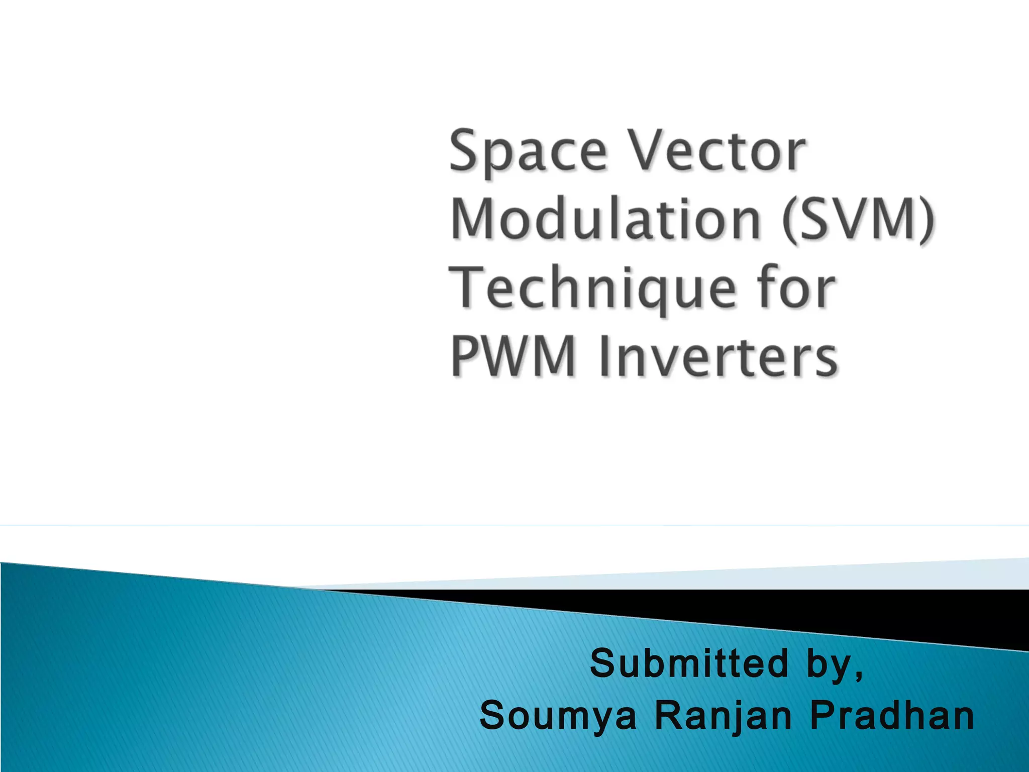
![Space Vector Modulation
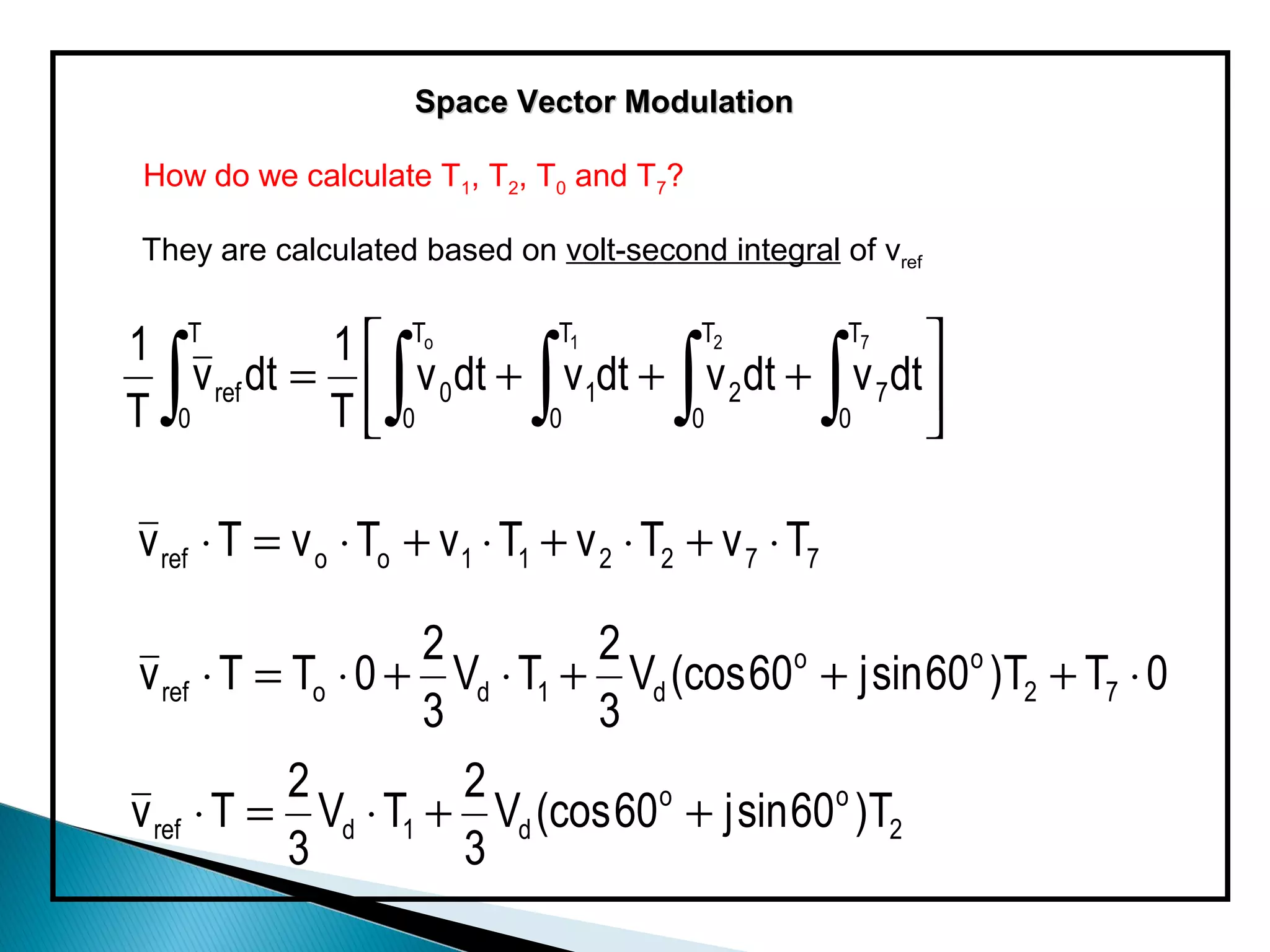
2 2
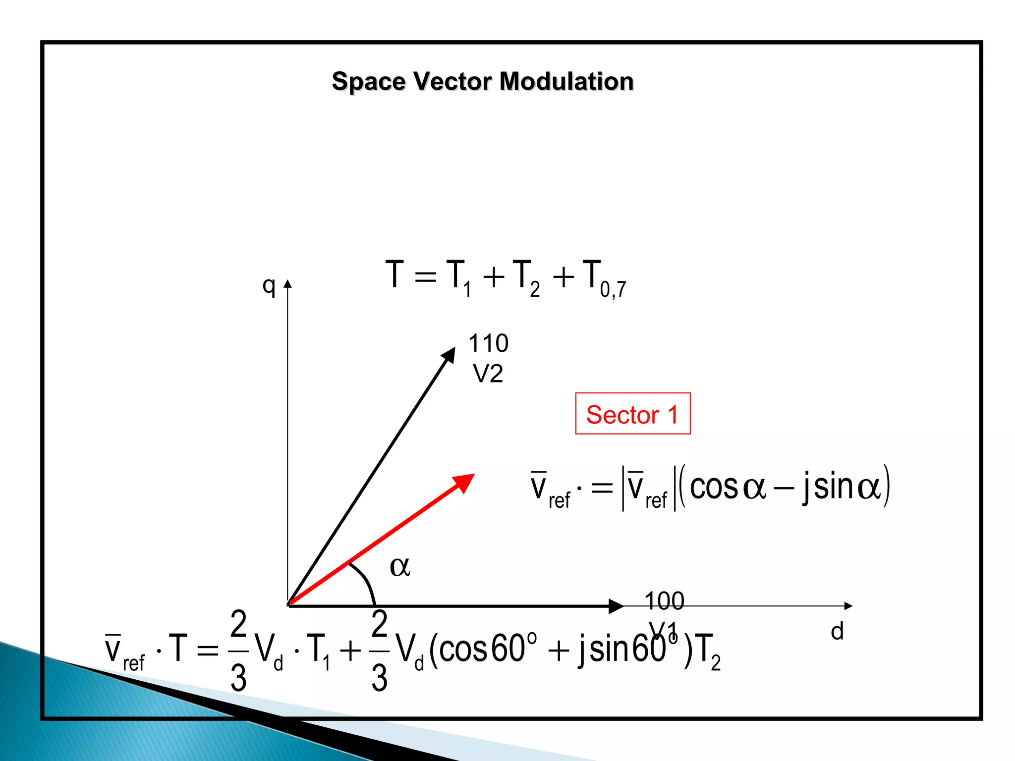
v ref ⋅ T = Vd ⋅ T1 + Vd (cos 60o + j sin 60o )T2
3 3
2 1 1
T v ref cos α = Vd T1 + Vd T2 T v ref sin α = Vd T2
3 3 3
Solving for T1, T2 and T0,7 gives:
T1= 3/2 m[ (T/√3) cos α - (1/3)T sin α ]
T2= mT sin α
where,
M= Vref/ (Vd/ √3)](https://image.slidesharecdn.com/svpwmpresentationsoumyaranjanpradhan-121126042858-phpapp01/75/Svpwm-24-2048.jpg)
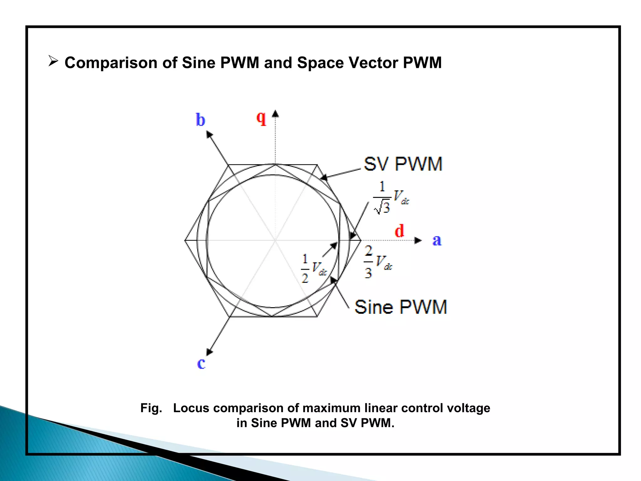
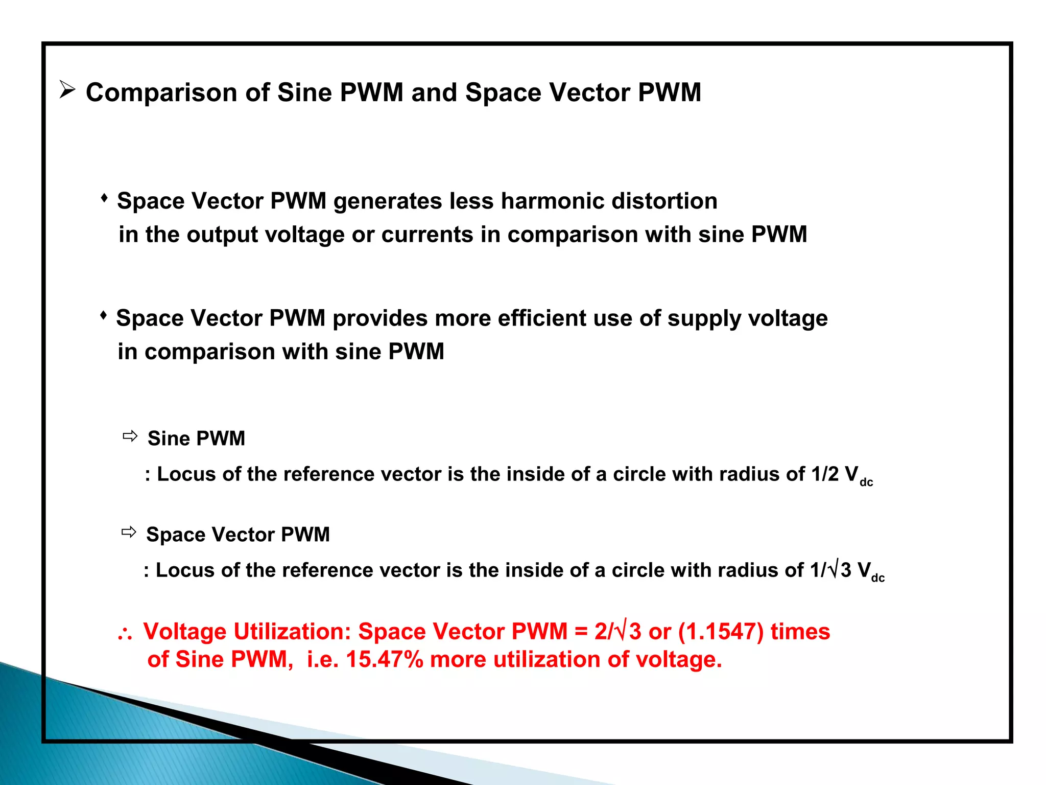


The document discusses space vector pulse width modulation (SVM) techniques for three-phase voltage source inverters. It explains the principles of SVM including coordinate transformation, reference voltage approximation using switching vectors, and calculation of switching times. Key advantages of SVM over sinusoidal PWM are more efficient voltage utilization and less output harmonic distortion. SVM allows the reference vector locus to reach the maximum circle compared to the inner circle for sinusoidal PWM, improving voltage utilization by around 15%.