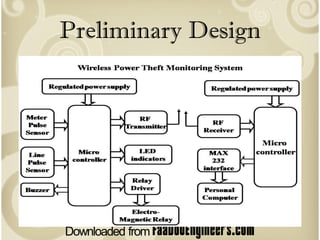
Wireless Power Theft
       Monitoring
Guide & Co-ordinator : Sri   Manaji A Gajare

Kamesh S Patil (3PD07EC021)
Kiran C V (3PD07EC024)
B M Vikas (3PD07EC011)
Pradeep Kanti (3PD05EC065)
Introduction
• Electricity theft is at the center of focus all over the
  world but electricity theft in India has a significant
  effect on the Indian economy, as this figure is
  considerably high.
• The losses, experts say, are currently 29 % of the total
  generation, which equals a shocking Rs 45,000 crore in
  the fiscal year 2009-10
• According to experts, if not for these losses over a
  decade now, India could have built two mega power
  plants of around 4,000 MW capacity every year
• Power loss in 2001-02 was 32.86% and increased to
  34.78% in 2003-04 . In 2008-09 , it stood at 28.44% but
  currently the figure is again 29%. It is as high as 51% in
  Jharkhand, 45% in Madhya Pradesh and 40% in Bihar.
The normal practice for power theft is to short the input
and output terminals or to place a magnet on the wheel
in case of old meters.
Few other ways for Power theft are
• Use of single phase supply from three phase supply.

• Disconnected neutral from both the ends.

• Used earth/separate neutral for return circuit.

• Connecting phase voltage to neutral of used single phase supply. Potential
  difference w.r.t. neutral of used single phase supply is zero. Hence power,
  product of voltage and current, will be zero.

• Isolating neutral from both ends.

• Drilling pin hole in meter box and in meter near MRI port.

• Disturbing electronic common reference point of measurement.
Literature Survey
These are some of the more common methods of identifying
   electricity theft today:

• Financial Rewards - Utility companies encourage consumers to
  report electricity theft, sometimes offering big rewards for
  information leading to conviction of anyone stealing electricity.
  Unfortunately, most cases are never identified.
• Periodic Checks - Electricity theft frequently takes place after
  service has been disconnected. Some utility companies periodically
  check disconnected meters if the customer has not contacted them
  to reconnect service. This labor-intensive, manual process has little
  chance of success.
• Meter Readers - Utility meter readers typically suspect that
  electricity theft is taking place when they find a broken meter tag or
  other signs of tampering. But as more utility companies outsource
  the meter reading function to third parties, training meter readers
  to detect theft is becoming more difficult and less efficient. In
  addition, third party meter readers do not read disconnected
  meters
Developments until now :
• Power theft detection circuit
Patent number : 4532471 ( 30.07.1985)

         This invention relates to a method and apparatus for detecting the
   theft of power when a short circuit jumper is coupled across a line
   conductor passing through watt-hour meter. However the method is
   costlier to be implemented and it has no way of alerting the authorities
   unless a regular survey is done.


• Power theft detection system
 Patent number : US20080109387A1(May 8th 2008)

         The system finds out the power theft by monitoring the total power
   consumption, receiving the delivered power data that includes data
   delivered to a number of users. Determining the amount of difference
   between them, thus finding out if power theft has occurred. But there lies
   no specific way to find out where the power theft has occurred
Problem definition
• Ineffective and inefficient present methods of detecting
  and preventing Power theft cause a revenue loss along with
  damage to personal and Public property

• Large amount of power shortage is caused due to power
  theft

• One of the challenges in stopping power theft is the
  difficulty in detecting power theft. In particular it is difficult
  to find the exact location where power theft is occurring.

• Measurement of parameters like power line current and
  power line voltage has not been available in a satisfactory
  way to optimize power network management
Motivation
• The motivation for us to take up this project is the current inefficient
  distribution system of the electricity boards all over the world.
• Also the present inability of the authorities in applying the existing laws in
  a stringent form has encouraged more and more people to involve in such
  unlawful activities.
• In case we develop a effective system to remotely monitor the use of
  power and are able to detect power theft at the exact location in a
  accurate and cost effective way, such huge losses can be prevented.
• This kind of money could definitely be used for the development of the
  quality of electricity board and its service. The severe power shortage can
  be overcome by the implementation of our simple system.
• More over this kind of implementation of proper billing to all the
  customers would reduce the reckless use of power and would surely help
  us to build a greener and more eco friendly environment for ourselves.
• As the majority of the power we generated is by burning coal, which adds
  to the already severe problem of the green house effect.
• Thus our group has been motivated to bring up this completely unique
  method of remotely sensing power theft in most of the possible ways.
Preliminary Design
The major building blocks of this
project are:

•   Regulated power supply.
•   RF transmitter and Receiver.
•   Two Micro controller boards.
•   Serial Port interfacing
•   PC
•   Meter and line pulse sensor
•   Relay system
•   MAX 232 Interface
• In our system, a micro controller is interfaced with an
  energy metering circuit, current sensing circuit, RF
  communication link & a contactor to make or break power
  line. At the sub-station end, a pc is connected with a RF link
  to communicate with all energy meters & a buzzer

• In normal condition, micro controller reads energy pulses &
  current signals. If current is drawing &energy pulses are
  normal, then no power theft is being done & the o/p is
  connected. If current is drawing & energy pulses are not
  coming, then it indicates power theft. So microcontroller
  trips the o/p using relay. This information is sent to
  substation using wireless communication

• In the substation, it receives the information in the form of
  digital codes & on decoding it, we can know at which house
  power theft occurred.
• Microcontroller PIC16F73
• The PIC16F73 CMOS FLASH-based 8-bit microcontroller
• Operating speed: DC - 20 MHz clock input
                 DC - 200 ns instruction cycle
• Features 8 channels of 8-bit Analog-to-Digital (A/D) converter
• Up to 8K x 14 words of FLASH Program Memory, Up to 368 x 8 bytes
  of Data Memory (RAM)
• A synchronous serial port that can be configured as either 3-wire
  SPI or 2-wire I2C bus,
• a Universal Synchronous Asynchronous Receiver
  Transmitter(USART)
• a Parallel Slave Port.
• Only 35 single word instructions to learn
• Interrupt capability (up to 12 sources)
• Eight level deep hardware stack
RF Transceiver

•   The 433 MHz Parallax RF Transceiver Module

•   3.3 to 5.0VDC, Transmit: 12mA, Receive: 6.1 mA
          Power Down: 11.5 uA

•   High speed data transfer rates: 1200-9600 bps

•   Asynchronous serial data (TTL/CMOS compatible)

•   SIP header allows for ease of use with breadboards

•   Compatible with most microcontrollers including the Propeller chip and
    all BASIC Stamp models

•   Power-down mode for conservative energy usage (longer battery life)

•   Line of sight range up to 250 feet (depending on operating conditions)
RF Receiver
• The ST-RX02-ASK

• A effective low cost solution for using at 315/433.92 MHZ.

• Receiver Frequency: 315 / 433.92 MHZ

• Typical sensitivity: -105dBm

• Supply Current: 3.5mA

• IF Frequency:1MHz
Objective
• Real-time Power monitoring at houses.
• Sensing the power theft at the exact location.
• Transmitting the information over wireless, to
  substation
Conclusion
• This project of ours is aimed at reducing the heavy power and
  revenue losses that occur due to power theft by the customers.
• We by this design would like to conclude that the power theft can
  be effectively curbed by detecting where the power theft occurs
  inform the authorities. Also a automatic circuit breaker may be
  integrated to the unit so as to remotely cut off the power supply to
  the house or consumer who tries to indulge in power theft.
• The ability of our system to inform or send data digitally to a
  remote station using wireless radio link adds a large amount of
  possibilities to the way the power supply is controlled by the
  electricity board.
• We have come up with is fool proof when it comes to detecting and
  preventing the power theft as, we have taken into consideration a
  large number of possibilities in which the power theft may occur
  and have designed accordingly to prevent it.
• Thus by the above mentioned design we can successfully and
  effectively address the problems related to power theft by the
  consumers, in a completely automated, wire-free, cost effective and
  most importantly a reliable way.
Reference
• IEEE links for this project:


• http://ieeexplore.ieee.org/Xplore/login.jsp?url=http%3
  A%2F%2Fieeexplore.ieee.org%2Fiel5%2F4918025%2F4
  918026%2F04918176.pdf%3Farnumber%3D4918176&
  authDecision=-203
• http://ieeexplore.ieee.org/Xplore/login.jsp?url=http%3
  A%2F%2Fieeexplore.ieee.org%2Fiel5%2F4035454%2F4
  078480%2F04078503.pdf%3Farnumber%3D4078503&
  authDecision=-203

Wireless power-theft-monitering-ppt

  • 1.
    Wireless Power Theft Monitoring Guide & Co-ordinator : Sri Manaji A Gajare Kamesh S Patil (3PD07EC021) Kiran C V (3PD07EC024) B M Vikas (3PD07EC011) Pradeep Kanti (3PD05EC065)
  • 2.
  • 3.
    • Electricity theftis at the center of focus all over the world but electricity theft in India has a significant effect on the Indian economy, as this figure is considerably high. • The losses, experts say, are currently 29 % of the total generation, which equals a shocking Rs 45,000 crore in the fiscal year 2009-10 • According to experts, if not for these losses over a decade now, India could have built two mega power plants of around 4,000 MW capacity every year • Power loss in 2001-02 was 32.86% and increased to 34.78% in 2003-04 . In 2008-09 , it stood at 28.44% but currently the figure is again 29%. It is as high as 51% in Jharkhand, 45% in Madhya Pradesh and 40% in Bihar.
  • 5.
    The normal practicefor power theft is to short the input and output terminals or to place a magnet on the wheel in case of old meters.
  • 6.
    Few other waysfor Power theft are • Use of single phase supply from three phase supply. • Disconnected neutral from both the ends. • Used earth/separate neutral for return circuit. • Connecting phase voltage to neutral of used single phase supply. Potential difference w.r.t. neutral of used single phase supply is zero. Hence power, product of voltage and current, will be zero. • Isolating neutral from both ends. • Drilling pin hole in meter box and in meter near MRI port. • Disturbing electronic common reference point of measurement.
  • 7.
  • 8.
    These are someof the more common methods of identifying electricity theft today: • Financial Rewards - Utility companies encourage consumers to report electricity theft, sometimes offering big rewards for information leading to conviction of anyone stealing electricity. Unfortunately, most cases are never identified. • Periodic Checks - Electricity theft frequently takes place after service has been disconnected. Some utility companies periodically check disconnected meters if the customer has not contacted them to reconnect service. This labor-intensive, manual process has little chance of success. • Meter Readers - Utility meter readers typically suspect that electricity theft is taking place when they find a broken meter tag or other signs of tampering. But as more utility companies outsource the meter reading function to third parties, training meter readers to detect theft is becoming more difficult and less efficient. In addition, third party meter readers do not read disconnected meters
  • 9.
    Developments until now: • Power theft detection circuit Patent number : 4532471 ( 30.07.1985) This invention relates to a method and apparatus for detecting the theft of power when a short circuit jumper is coupled across a line conductor passing through watt-hour meter. However the method is costlier to be implemented and it has no way of alerting the authorities unless a regular survey is done. • Power theft detection system Patent number : US20080109387A1(May 8th 2008) The system finds out the power theft by monitoring the total power consumption, receiving the delivered power data that includes data delivered to a number of users. Determining the amount of difference between them, thus finding out if power theft has occurred. But there lies no specific way to find out where the power theft has occurred
  • 10.
  • 11.
    • Ineffective andinefficient present methods of detecting and preventing Power theft cause a revenue loss along with damage to personal and Public property • Large amount of power shortage is caused due to power theft • One of the challenges in stopping power theft is the difficulty in detecting power theft. In particular it is difficult to find the exact location where power theft is occurring. • Measurement of parameters like power line current and power line voltage has not been available in a satisfactory way to optimize power network management
  • 12.
  • 13.
    • The motivationfor us to take up this project is the current inefficient distribution system of the electricity boards all over the world. • Also the present inability of the authorities in applying the existing laws in a stringent form has encouraged more and more people to involve in such unlawful activities. • In case we develop a effective system to remotely monitor the use of power and are able to detect power theft at the exact location in a accurate and cost effective way, such huge losses can be prevented. • This kind of money could definitely be used for the development of the quality of electricity board and its service. The severe power shortage can be overcome by the implementation of our simple system. • More over this kind of implementation of proper billing to all the customers would reduce the reckless use of power and would surely help us to build a greener and more eco friendly environment for ourselves. • As the majority of the power we generated is by burning coal, which adds to the already severe problem of the green house effect. • Thus our group has been motivated to bring up this completely unique method of remotely sensing power theft in most of the possible ways.
  • 14.
  • 15.
    The major buildingblocks of this project are: • Regulated power supply. • RF transmitter and Receiver. • Two Micro controller boards. • Serial Port interfacing • PC • Meter and line pulse sensor • Relay system • MAX 232 Interface
  • 16.
    • In oursystem, a micro controller is interfaced with an energy metering circuit, current sensing circuit, RF communication link & a contactor to make or break power line. At the sub-station end, a pc is connected with a RF link to communicate with all energy meters & a buzzer • In normal condition, micro controller reads energy pulses & current signals. If current is drawing &energy pulses are normal, then no power theft is being done & the o/p is connected. If current is drawing & energy pulses are not coming, then it indicates power theft. So microcontroller trips the o/p using relay. This information is sent to substation using wireless communication • In the substation, it receives the information in the form of digital codes & on decoding it, we can know at which house power theft occurred.
  • 17.
    • Microcontroller PIC16F73 •The PIC16F73 CMOS FLASH-based 8-bit microcontroller • Operating speed: DC - 20 MHz clock input DC - 200 ns instruction cycle • Features 8 channels of 8-bit Analog-to-Digital (A/D) converter • Up to 8K x 14 words of FLASH Program Memory, Up to 368 x 8 bytes of Data Memory (RAM) • A synchronous serial port that can be configured as either 3-wire SPI or 2-wire I2C bus, • a Universal Synchronous Asynchronous Receiver Transmitter(USART) • a Parallel Slave Port. • Only 35 single word instructions to learn • Interrupt capability (up to 12 sources) • Eight level deep hardware stack
  • 18.
    RF Transceiver • The 433 MHz Parallax RF Transceiver Module • 3.3 to 5.0VDC, Transmit: 12mA, Receive: 6.1 mA Power Down: 11.5 uA • High speed data transfer rates: 1200-9600 bps • Asynchronous serial data (TTL/CMOS compatible) • SIP header allows for ease of use with breadboards • Compatible with most microcontrollers including the Propeller chip and all BASIC Stamp models • Power-down mode for conservative energy usage (longer battery life) • Line of sight range up to 250 feet (depending on operating conditions)
  • 19.
    RF Receiver • TheST-RX02-ASK • A effective low cost solution for using at 315/433.92 MHZ. • Receiver Frequency: 315 / 433.92 MHZ • Typical sensitivity: -105dBm • Supply Current: 3.5mA • IF Frequency:1MHz
  • 20.
  • 21.
    • Real-time Powermonitoring at houses. • Sensing the power theft at the exact location. • Transmitting the information over wireless, to substation
  • 22.
  • 23.
    • This projectof ours is aimed at reducing the heavy power and revenue losses that occur due to power theft by the customers. • We by this design would like to conclude that the power theft can be effectively curbed by detecting where the power theft occurs inform the authorities. Also a automatic circuit breaker may be integrated to the unit so as to remotely cut off the power supply to the house or consumer who tries to indulge in power theft. • The ability of our system to inform or send data digitally to a remote station using wireless radio link adds a large amount of possibilities to the way the power supply is controlled by the electricity board. • We have come up with is fool proof when it comes to detecting and preventing the power theft as, we have taken into consideration a large number of possibilities in which the power theft may occur and have designed accordingly to prevent it. • Thus by the above mentioned design we can successfully and effectively address the problems related to power theft by the consumers, in a completely automated, wire-free, cost effective and most importantly a reliable way.
  • 24.
    Reference • IEEE linksfor this project: • http://ieeexplore.ieee.org/Xplore/login.jsp?url=http%3 A%2F%2Fieeexplore.ieee.org%2Fiel5%2F4918025%2F4 918026%2F04918176.pdf%3Farnumber%3D4918176& authDecision=-203 • http://ieeexplore.ieee.org/Xplore/login.jsp?url=http%3 A%2F%2Fieeexplore.ieee.org%2Fiel5%2F4035454%2F4 078480%2F04078503.pdf%3Farnumber%3D4078503& authDecision=-203