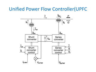
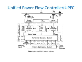
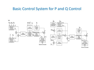
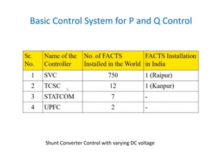
Unified Power Flow Controller(UPFC
Control Structure
• With suitable electronic controls, the UPFC can cause the series-injected
voltage vector to vary rapidly and continuously in magnitude and/or
angle as desired.
• It is not only able to establish an operating point within a wide range of
possible P, Q conditions on the line, but also has the inherent capability
to transition rapidly from one such achievable operating point to any
other
• The control of the UPFC is based upon the vector-control approach
• The term vector, instead of phasor, is used in this section to represent a
set of three instantaneous phase variables, voltages, or currents that
sum to zero.
Unified Power Flow Controller(UPFC
• The symbols v and i are used for voltage and current vectors.
• These vectors are not stationary, but move around a fixed point in
the plane as the values of the phase variables change, describing
various trajectories
• Which become circles, identical to those obtained with phasors,
when the phase variables represent a balanced, steady-state
condition.
• these vectors in an orthogonal coordinate system with p and q axes
such that the p axis is always coincident with the instantaneous
voltage vector v and the q axisis in quadrature with it.
Unified Power Flow Controller(UPFC
Control Structure
• In this coordinate system the p-axis current component, ip
accounts for the instantaneous real power and the q-axis current
component, iq, for the reactive power.
• Under balanced steady-state conditions, the p-axis and q-axis
components of the voltage and current vector are constant quantities.
• This characteristic of the described vector representation makes it
highly suitable for the control of the UPFC by facilitating the
decoupled control of the real and reactive current components.
• The UPFC control system may, in the previously established manner,
be divided functionally into internal (or converter) control and
functional operation control.
Unified Power Flow Controller(UPFC
• The internal controls operate the two converters so as to
produce the commanded series injected voltage and,
simultaneously, draw the desired shunt reactive current.
• The internal controls provide gating signals to the converter
valves so that the converter output voltages will properly
respond to the internal reference variables, ipref,iqref and
Vpqref
• The series converter responds directly and independently to
the demand for series voltage vector injection.
• The shunt converter operates under a closed-loop current
control structure whereby the shunt real and reactive
power components are independently controlled.
Unified Power Flow Controller(UPFC
• The shunt real power is dictated by another control loop that acts
to maintain a preset voltage level on the dc link, thereby providing
the real power supply or sink needed for the support of the series
voltage injection.
• That is the control loop for the shunt real power ensures the
required real power balance between the two converters.
• As mentioned previously, the converters do not (and could not)
exchange reactive power through the link.
• The external or functional operation control defines the functional
operating mode of the UPFC and is responsible for generating the
internal references,
Unified Power Flow Controller(UPFC
• The functional operating modes and compensation
demands, represented by external (or system) reference
inputs, can be set manually by the operator or dictated by
an automatic system optimization control to meet specific
operating and contingency requirements.
• The capability of unrestricted series voltage injection
together with independently controllable reactive power
exchange offered by the circuit structure of two back-to-
back converters, facilitate several operating and control
modes for the UPFC.
• These include the option of reactive shunt compensation
and the free control of series voltage injection according
to a prescribed functional approach selected for power
flow control.
Unified Power Flow Controller(UPFC
Functional Control of Shunt Converter)
• The shunt converter is operated so as to draw a controlled
current, ish, from the line.
• One component of this current, ishp, is automatically
determined by the requirement to balance the real power of
the series converter.
• The other current component, ishq is reactive and can be set
to any desired reference level (inductive or capacitive) within
the capability of the converter.
• The reactive compensation control modes of the shunt
converter are, of course, very similar to those commonly
employed for the STATCOM and conventional static var
compensator.
Functional Control of Shunt Converter)
Reactive power control mode:
• In this mode,the reference input is an inductive or
capacitive var request.
• The shunt converter control translates the var reference
into a corresponding shunt current request and adjusts
the gating of the converter to establish the desired
current.
• The control in a closed-loop arrangement uses current
feedback signals obtained from the output current of the
shunt converter to enforce the current reference.
• A feedback signal representing the dc bus voltage, ua", is
also used to ensure the necessary dc link voltage.
Functional Control of Shunt Converter)
Voltage control mode:
• In voltage control mode (which is normally used in
practical applications).
• The shunt converter reactive current is automatically
regulated to maintain the transmission line voltage to a
reference value at the point of connection, with a defined
droop characteristic.
• The droop factor defines the per unit voltage error per unit
of converter reactive current within the current range of
the converter.
• The automatic voltage control uses voltage feedback
signals, usually representing the magnitude of the positive
sequence component of bus voltage v1
• The series converter controls the magnitude and angle of the
voltage vector fro injected in series with the line.
• This voltage injection is, directly or indirectly, always intended to
influence the flow of power on the line.
• Vpq is dependent on the operating mode selected for the UPFC to
control power flow. The principal operating modes are as follows in
the next subsections.
Direct Voltage Control Mode:
• The series converter simply generates the voltage vector, ipq, with
the magnitude and phase angle requested by the reference input.
Functional Control of the Series Converter
• This operating mode may be advantageous when a separate
system optimization control coordinates the operation of
the UPFC and other FACTS controllers employed in the
transmission system.
• Special functional cases of direct voltage injection include
those having dedicated control objectives
• Eg. when the injected voltage vector, ipq, is kept in phase
with the system voltage for voltage magnitude control, or
• In quadrature with it for controlled "quadrature boosting,"
or in quadrature with the line current vector, l, to provide
controllable reactive series compensation.
Functional Control of the Series Converter
Bus Voltage regulation and control mode
• The injected voltagevector, vpq, is kept in phase with
the "input" bus voltage vector fl and its magnitude is
controlled to maintain the magnitude "output" bus
voltage vector v2 at the given reference value.
Line compensation Mode:
• The magnitude of the injected voltage vector, vpq, is
controlled in proportion to the magnitude of the line
current, i, so that the series insertion emulates an
impedance when viewed from the line.
Functional Control of the Series Converter
• The desired impedance is specified by reference input and in
general it may be a complex impedance with resistive and
reactive components of either polarity.
• A special case of impedance compensation occurs when the
injected voltage is kept in quadrature with respect to the line
current to emulate purely reactive (capacitive or inductive)
compensation.
• This operating mode may be selected to match existing series
capacitive line compensation in the system.
Functional Control of the Series Converter
Phase Angle Regulation control Mode:
• The injected voltage vector vpq is controlled with
respect to the "input" bus voltage vector v1 so that the
"output" bus voltage vector v2 is phase shifted,
without any magnitude change, relative to v1 by an
angle specified by the reference input.
• One special case of phase shifting occurs when vpq is
kept in quadrature with v1 to emulate the "quadrature
booster."
Functional Control of the Series Converter
Automatic power Flow control mode The magnitude and angle of
the injected voltage vector, fro, is controlled so as to force such a
line current vector, i, that
results in the desired real and reactive power flow in the line.
In automatic power flow control mode, the series injected voltage is
determined automatically and continuously by a closed-loop control
system to ensure that the desired P and Q are maintained despite
power system changes.
The transmission line containing the UPFC thus appears to the rest
of the power system as a high impedance power source or sink. This
operating mode, which is not achievable with conventional line
compensating equipment, has far reaching possibilities for power
flow scheduling and management.
It can also be applied effectively to handle dynamic system
disturbances (e.g., to damp power oscillations).
Basic Control System for P and Q Control
• The UPFC has many possible operating modes.
• But only the automatic power flow control mode,
providing independent control for real and reactive power
flow in the line.
• The control mode utilizes most of the unique capabilities
of the UPFC and it is expected to be used as the basic
mode in the majority of practical applications, just as the
shunt compensation is used normally
for automatic voltage control.
• Accordingly, block diagrams giving greater details of the
control schemes are shown for the series converter and
for the shunt converter.
• The control scheme shown assumes that the series
converter can generate output voltage with controllable
magnitude and angle at a given dc bus voltage
Basic Control System for P and Q Control
1. The control scheme for the shunt converter shown in Figure
also assumes that the converter can generate output voltage
with controllable magnitude and angle.
2. However, this may not always be the case, since the converter
losses and harmonics can be reduced by allowing the dc voltage
to vary according to the prevailing shunt compensation
demand.
3. Although the variation of the dc voltage inevitably reduces the
attainable magnitude of the injected series voltage when the
shunt converter is operated with high reactive power
absorption, in many applications this may be an acceptable
trade-off.
Basic Control System for P and Q Control
Shunt Converter Control with varying DC voltage
Basic Control System for P and Q Control
Shunt Converter Control with varying DC voltage
Basic Control System for P and Q Control
Shunt Converter Control with varying DC voltage
UPFC Installations
http://read.pudn.com/downloads348/ebook/1520137/AEP%20UPFC.pdf
https://www.researchgate.net/publication/262423633_Power_Flow_Control
_using_UPFC_Device
http://www2.ece.ohio-state.edu/~longya/ECE844/UPFC-Gyugyi.pdf
https://www.youtube.com/watch?v=0oOOVkpycJM
NITTR video on UPFC 21.00-34.00 minutes

Unified Power Flow Controller(upfc) 2

  • 1.
    Unified Power FlowController(UPFC Control Structure • With suitable electronic controls, the UPFC can cause the series-injected voltage vector to vary rapidly and continuously in magnitude and/or angle as desired. • It is not only able to establish an operating point within a wide range of possible P, Q conditions on the line, but also has the inherent capability to transition rapidly from one such achievable operating point to any other • The control of the UPFC is based upon the vector-control approach • The term vector, instead of phasor, is used in this section to represent a set of three instantaneous phase variables, voltages, or currents that sum to zero.
  • 2.
    Unified Power FlowController(UPFC • The symbols v and i are used for voltage and current vectors. • These vectors are not stationary, but move around a fixed point in the plane as the values of the phase variables change, describing various trajectories • Which become circles, identical to those obtained with phasors, when the phase variables represent a balanced, steady-state condition. • these vectors in an orthogonal coordinate system with p and q axes such that the p axis is always coincident with the instantaneous voltage vector v and the q axisis in quadrature with it.
  • 3.
    Unified Power FlowController(UPFC Control Structure • In this coordinate system the p-axis current component, ip accounts for the instantaneous real power and the q-axis current component, iq, for the reactive power. • Under balanced steady-state conditions, the p-axis and q-axis components of the voltage and current vector are constant quantities. • This characteristic of the described vector representation makes it highly suitable for the control of the UPFC by facilitating the decoupled control of the real and reactive current components. • The UPFC control system may, in the previously established manner, be divided functionally into internal (or converter) control and functional operation control.
  • 4.
    Unified Power FlowController(UPFC • The internal controls operate the two converters so as to produce the commanded series injected voltage and, simultaneously, draw the desired shunt reactive current. • The internal controls provide gating signals to the converter valves so that the converter output voltages will properly respond to the internal reference variables, ipref,iqref and Vpqref • The series converter responds directly and independently to the demand for series voltage vector injection. • The shunt converter operates under a closed-loop current control structure whereby the shunt real and reactive power components are independently controlled.
  • 5.
    Unified Power FlowController(UPFC • The internal controls operate the two converters so as to produce the commanded series injected voltage and, simultaneously, draw the desired shunt reactive current. • The internal controls provide gating signals to the converter valves so that the converter output voltages will properly respond to the internal reference variables, ipref,iqref and Vpqref • The series converter responds directly and independently to the demand for series voltage vector injection. • The shunt converter operates under a closed-loop current control structure whereby the shunt real and reactive power components are independently controlled.
  • 6.
    Unified Power FlowController(UPFC • The shunt real power is dictated by another control loop that acts to maintain a preset voltage level on the dc link, thereby providing the real power supply or sink needed for the support of the series voltage injection. • That is the control loop for the shunt real power ensures the required real power balance between the two converters. • As mentioned previously, the converters do not (and could not) exchange reactive power through the link. • The external or functional operation control defines the functional operating mode of the UPFC and is responsible for generating the internal references,
  • 7.
    Unified Power FlowController(UPFC
  • 8.
    Unified Power FlowController(UPFC • The functional operating modes and compensation demands, represented by external (or system) reference inputs, can be set manually by the operator or dictated by an automatic system optimization control to meet specific operating and contingency requirements. • The capability of unrestricted series voltage injection together with independently controllable reactive power exchange offered by the circuit structure of two back-to- back converters, facilitate several operating and control modes for the UPFC. • These include the option of reactive shunt compensation and the free control of series voltage injection according to a prescribed functional approach selected for power flow control.
  • 9.
    Unified Power FlowController(UPFC
  • 10.
    Functional Control ofShunt Converter) • The shunt converter is operated so as to draw a controlled current, ish, from the line. • One component of this current, ishp, is automatically determined by the requirement to balance the real power of the series converter. • The other current component, ishq is reactive and can be set to any desired reference level (inductive or capacitive) within the capability of the converter. • The reactive compensation control modes of the shunt converter are, of course, very similar to those commonly employed for the STATCOM and conventional static var compensator.
  • 11.
    Functional Control ofShunt Converter) Reactive power control mode: • In this mode,the reference input is an inductive or capacitive var request. • The shunt converter control translates the var reference into a corresponding shunt current request and adjusts the gating of the converter to establish the desired current. • The control in a closed-loop arrangement uses current feedback signals obtained from the output current of the shunt converter to enforce the current reference. • A feedback signal representing the dc bus voltage, ua", is also used to ensure the necessary dc link voltage.
  • 12.
    Functional Control ofShunt Converter) Voltage control mode: • In voltage control mode (which is normally used in practical applications). • The shunt converter reactive current is automatically regulated to maintain the transmission line voltage to a reference value at the point of connection, with a defined droop characteristic. • The droop factor defines the per unit voltage error per unit of converter reactive current within the current range of the converter. • The automatic voltage control uses voltage feedback signals, usually representing the magnitude of the positive sequence component of bus voltage v1
  • 13.
    • The seriesconverter controls the magnitude and angle of the voltage vector fro injected in series with the line. • This voltage injection is, directly or indirectly, always intended to influence the flow of power on the line. • Vpq is dependent on the operating mode selected for the UPFC to control power flow. The principal operating modes are as follows in the next subsections. Direct Voltage Control Mode: • The series converter simply generates the voltage vector, ipq, with the magnitude and phase angle requested by the reference input. Functional Control of the Series Converter
  • 14.
    Functional Control ofthe Series Converter • This operating mode may be advantageous when a separate system optimization control coordinates the operation of the UPFC and other FACTS controllers employed in the transmission system. • Special functional cases of direct voltage injection include those having dedicated control objectives • Eg. when the injected voltage vector, ipq, is kept in phase with the system voltage for voltage magnitude control, or • In quadrature with it for controlled "quadrature boosting," or in quadrature with the line current vector, l, to provide controllable reactive series compensation.
  • 15.
    Functional Control ofthe Series Converter Bus Voltage regulation and control mode • The injected voltagevector, vpq, is kept in phase with the "input" bus voltage vector fl and its magnitude is controlled to maintain the magnitude "output" bus voltage vector v2 at the given reference value. Line compensation Mode: • The magnitude of the injected voltage vector, vpq, is controlled in proportion to the magnitude of the line current, i, so that the series insertion emulates an impedance when viewed from the line.
  • 16.
    Functional Control ofthe Series Converter • The desired impedance is specified by reference input and in general it may be a complex impedance with resistive and reactive components of either polarity. • A special case of impedance compensation occurs when the injected voltage is kept in quadrature with respect to the line current to emulate purely reactive (capacitive or inductive) compensation. • This operating mode may be selected to match existing series capacitive line compensation in the system.
  • 17.
    Functional Control ofthe Series Converter Phase Angle Regulation control Mode: • The injected voltage vector vpq is controlled with respect to the "input" bus voltage vector v1 so that the "output" bus voltage vector v2 is phase shifted, without any magnitude change, relative to v1 by an angle specified by the reference input. • One special case of phase shifting occurs when vpq is kept in quadrature with v1 to emulate the "quadrature booster."
  • 18.
    Functional Control ofthe Series Converter Automatic power Flow control mode The magnitude and angle of the injected voltage vector, fro, is controlled so as to force such a line current vector, i, that results in the desired real and reactive power flow in the line. In automatic power flow control mode, the series injected voltage is determined automatically and continuously by a closed-loop control system to ensure that the desired P and Q are maintained despite power system changes. The transmission line containing the UPFC thus appears to the rest of the power system as a high impedance power source or sink. This operating mode, which is not achievable with conventional line compensating equipment, has far reaching possibilities for power flow scheduling and management. It can also be applied effectively to handle dynamic system disturbances (e.g., to damp power oscillations).
  • 19.
    Basic Control Systemfor P and Q Control • The UPFC has many possible operating modes. • But only the automatic power flow control mode, providing independent control for real and reactive power flow in the line. • The control mode utilizes most of the unique capabilities of the UPFC and it is expected to be used as the basic mode in the majority of practical applications, just as the shunt compensation is used normally for automatic voltage control. • Accordingly, block diagrams giving greater details of the control schemes are shown for the series converter and for the shunt converter. • The control scheme shown assumes that the series converter can generate output voltage with controllable magnitude and angle at a given dc bus voltage
  • 20.
    Basic Control Systemfor P and Q Control
  • 21.
    Basic Control Systemfor P and Q Control 1. The control scheme for the shunt converter shown in Figure also assumes that the converter can generate output voltage with controllable magnitude and angle. 2. However, this may not always be the case, since the converter losses and harmonics can be reduced by allowing the dc voltage to vary according to the prevailing shunt compensation demand. 3. Although the variation of the dc voltage inevitably reduces the attainable magnitude of the injected series voltage when the shunt converter is operated with high reactive power absorption, in many applications this may be an acceptable trade-off.
  • 22.
    Basic Control Systemfor P and Q Control Shunt Converter Control with varying DC voltage
  • 23.
    Basic Control Systemfor P and Q Control Shunt Converter Control with varying DC voltage
  • 24.
    Basic Control Systemfor P and Q Control Shunt Converter Control with varying DC voltage
  • 25.