Downloaded 1,339 times


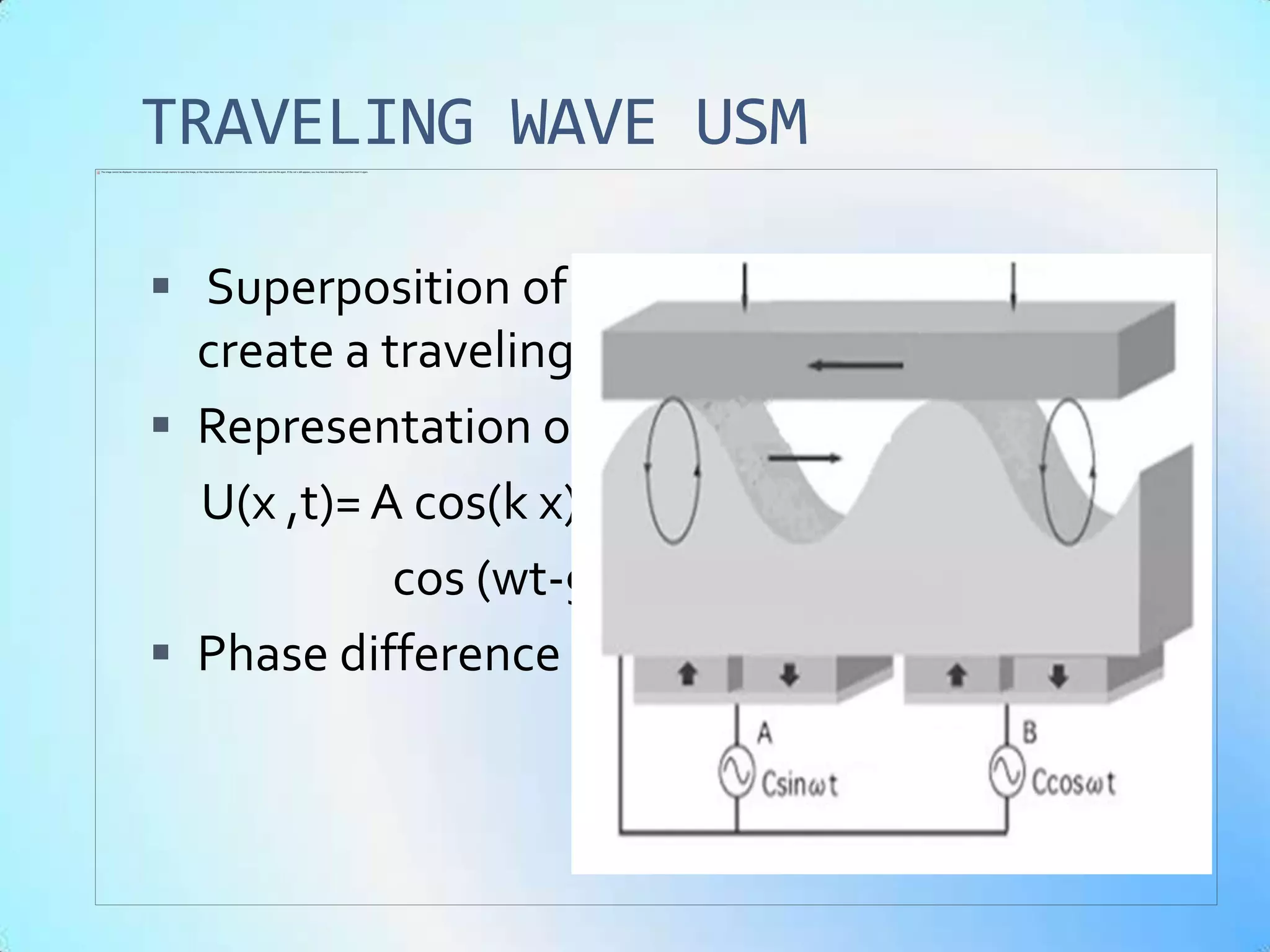


This document discusses ultrasonic motors. It begins with an introduction describing how ultrasonic motors were developed and their advantages over traditional motors at small scales. It then covers key topics such as piezoelectricity, poling, basic principles of operation, construction, types including standing wave and traveling wave motors, driver circuits, control techniques, applications, and advantages/disadvantages. In summary, the document provides an overview of ultrasonic motors, how they work using piezoelectric effects, their construction and operating principles, examples of different types, and their applications and benefits.