This document describes a prepaid energy meter system with theft detection. The system uses a microcontroller and GSM module to allow users to pay for electricity in advance, monitor their balance, and detect any internal or external theft. When theft is detected or the balance reaches zero, the system cuts power and sends alerts. It provides benefits like upfront payment, lower costs for utilities, and budgeting for consumers. The project is functioning well in testing but may require modifications for commercial use.
Presented by Group 3, including members Kirti Verma, Anchal Gupta, and Chandan Singh. Agenda includes various sections like Abstracts, Introductions, Characteristics, etc.
The project aims to provide an efficient prepaid energy meter with theft detection. It highlights traditional billing issues and outlines GSM-enabled theft detection features.
Key characteristics include revenue collection, credit loading, and transaction security. Components listed range from Arduino software to various electronic elements including ATmega328P.
Illustrates the system's block diagram and details the working mechanism involving EEPROMs, how energy units are calculated, and the role of the AT89S52 microcontroller.
Explains GSM functionalities for instruction transmission and the LCD's role in displaying information such as consumption and balances.
Describes the relay's operation in connecting/disconnecting power, and auxiliary components like LED indicators and crystal oscillators essential for circuit management.
Benefits include upfront payments, fraud detection, and ease for consumers such as budgeting and energy conservation, improving overall service delivery.
Future enhancements may include mini printers for billing and remote charging capabilities via telephone or wireless networks, promoting convenience.
Concludes that the project meets expectations in lab settings, with potential field applications following minor modifications to hardware and software.
CONTENTS :-
Abstracts
Introductions
Characterstics
Components
Block diagram
Working system
Specifications of some components
Benefits and utilities
Future scope
Conclusion
3.
ABSTRACT
Provide the adequatesupply to customers and collect
the fare effectively.
The imperfection in traditional billing systems.
To overcome this imperfections this project is
designed.
The application is mainly based on microcontroller.
4.
INTRODUCTIONS
The PrepaidEnergy Meter with Theft Detection System mainly works
for detecting internal as well as external energy theft. The system works
for theft detection and also allows user to use prepaid energy
meter functionality. Using this functionality user will able to pay in advance and
use the exact amount of energy.
The system starts with GSM modem Connection and first configures the user
number and gives authority to that number.
When the external or internal theft occurs in system, the system immediately
inform authority or user with message also system will able to send message
when the prepaid balance is low or Zero.
5.
Overall characteristics ofprepaid energy meter:-
Methodology
Collection of revenues
Loading the credit revenue in meter
Decrementing the revenue
Providing the alarm
Disconnection
Security of transaction
Unloading the revenue
6.
COMPONENTS :-
Software Specifications-
Arduino Compiler
MC Programming Language: C
Hardware Specifications -
ATmega328P AVR MC, Current Sensor, SIM 800 GSM Module, LCD’s, Relay, Relay
Driver IC, Vtg Regulator IC, Socket, Crystal Oscillator , Resistors, Capacitors,
Transistors, Cables & Connectors, Diodes, LED’s , Transformer/Adapter, Push
Button, Energy Meter and some Loads.
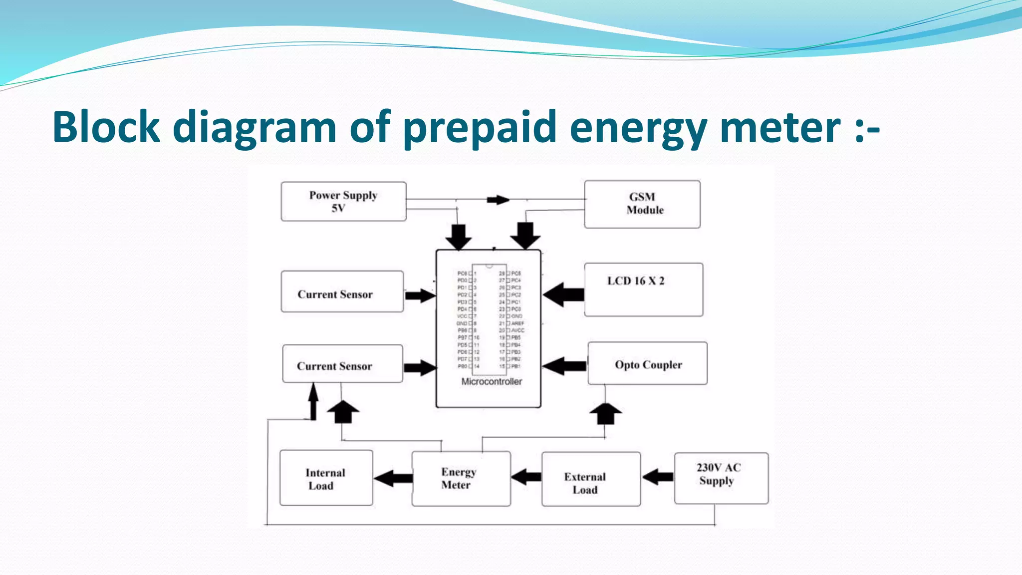
WORKING SYSTEM
Asimplest type of prepaid energy meter consists of 2 EEPROMs
interfaced to a microcontroller. The energy meter supplies pulses to the
microcontroller for every unit of energy consumed. The microcontroller
increases the spent energy unit by one and decreases the balance amount
in the EEPROM by the fixed tariff.
When meter balance reaches zero, the meter switches off
the electricity that powers your house. Indeed, the prepaid electricity
meter has a relay (an automatic switch) which disconnects the power
when there is no units left. When you top up, the meter balance increases
and the relays letselectricity flows again.
9.
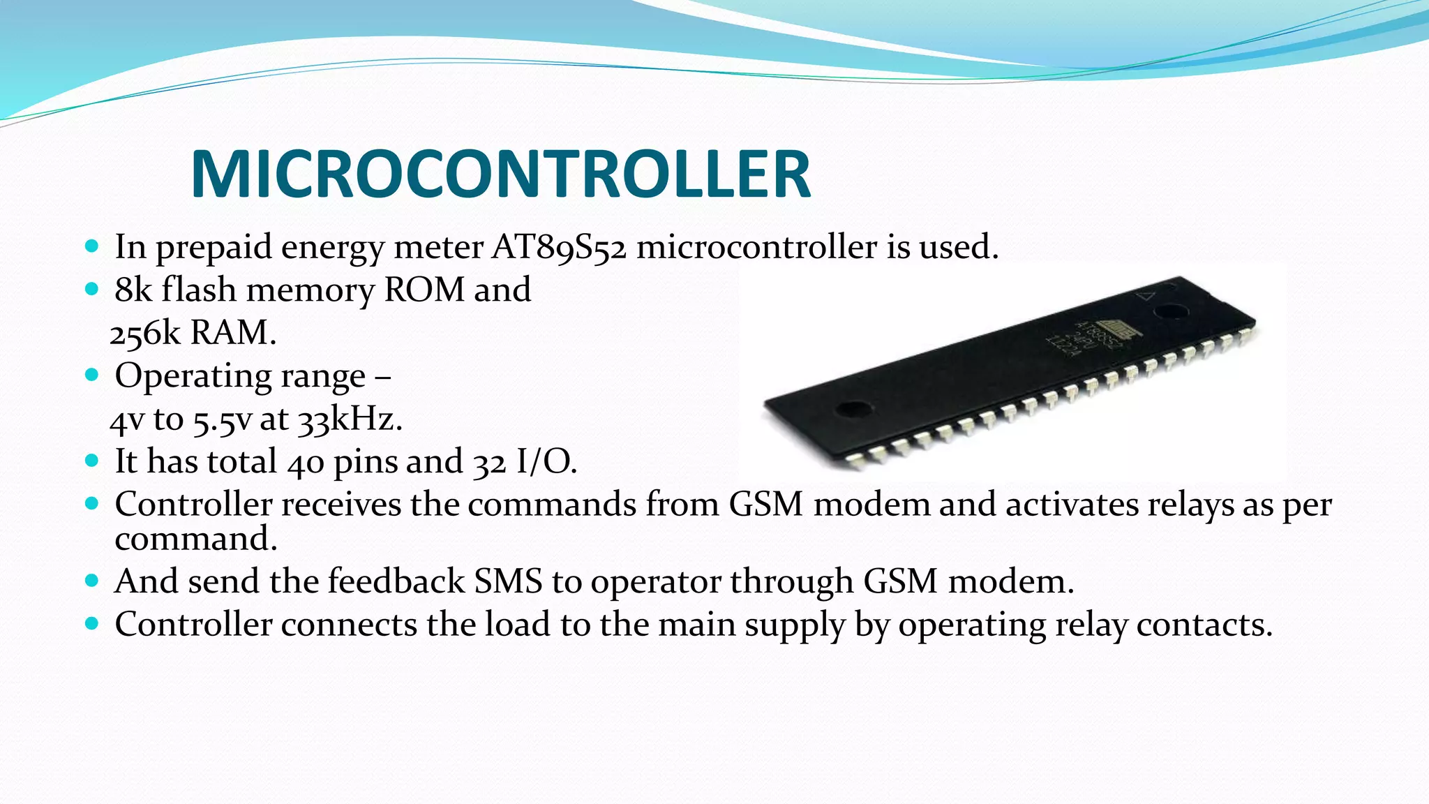
MICROCONTROLLER
In prepaidenergy meter AT89S52 microcontroller is used.
8k flash memory ROM and
256k RAM.
Operating range –
4v to 5.5v at 33kHz.
It has total 40 pins and 32 I/O.
Controller receives the commands from GSM modem and activates relays as per
command.
And send the feedback SMS to operator through GSM modem.
Controller connects the load to the main supply by operating relay contacts.
10.
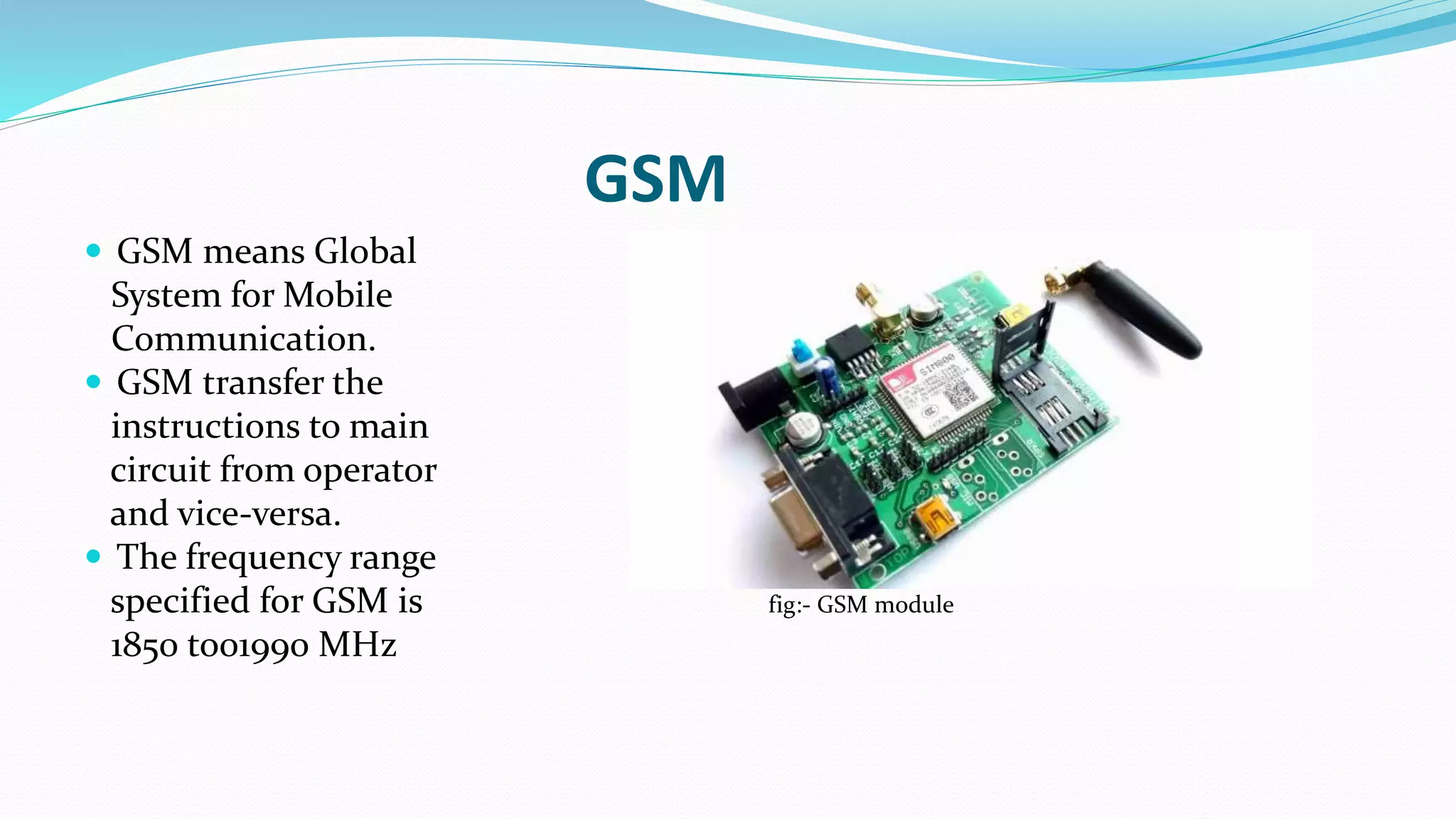
GSM
GSM meansGlobal
System for Mobile
Communication.
GSM transfer the
instructions to main
circuit from operator
and vice-versa.
The frequency range
specified for GSM is fig:- GSM module
1850 to01990 MHz
11.
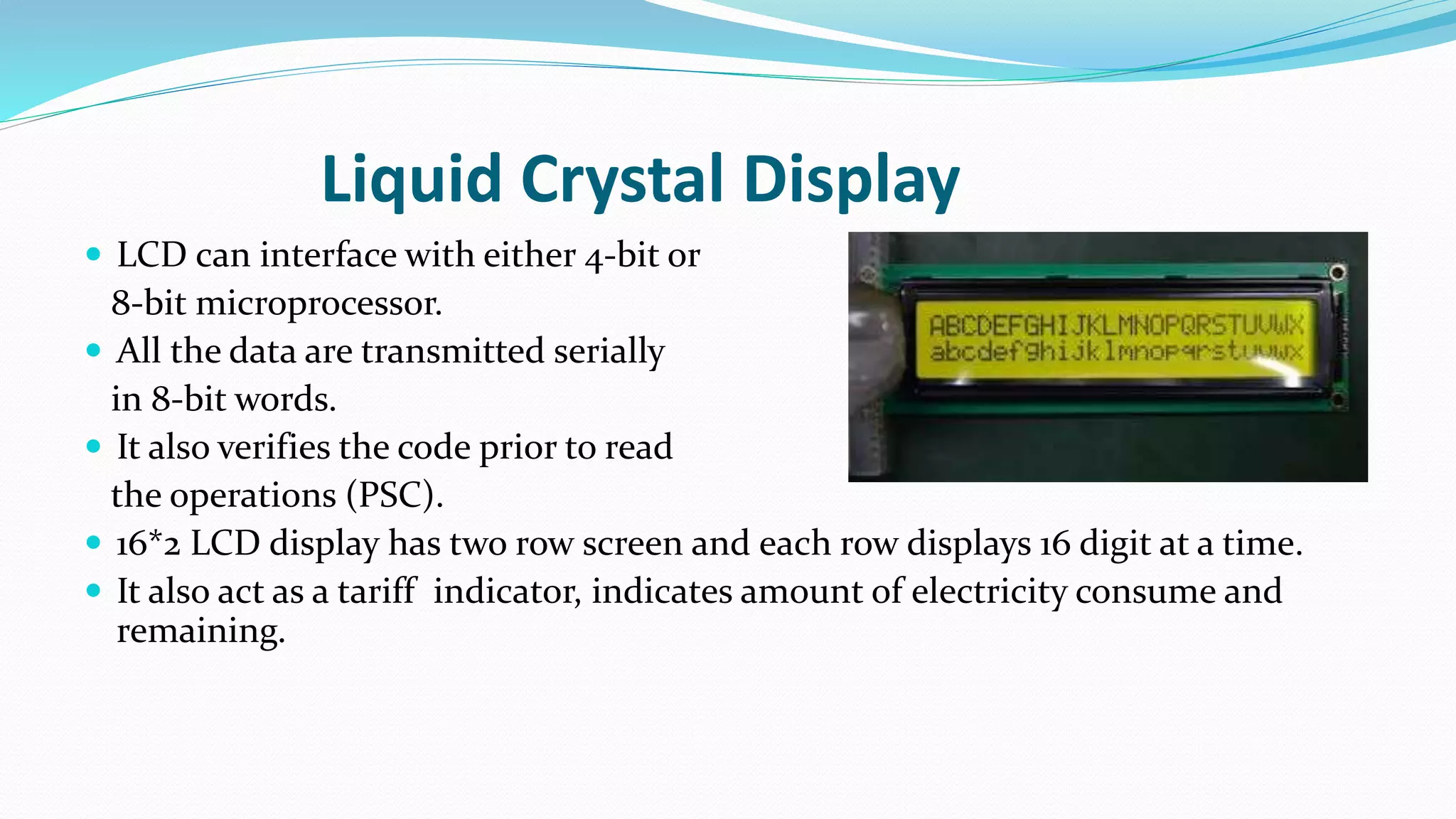
Liquid Crystal Display
LCD can interface with either 4-bit or
8-bit microprocessor.
All the data are transmitted serially
in 8-bit words.
It also verifies the code prior to read
the operations (PSC).
16*2 LCD display has two row screen and each row displays 16 digit at a time.
It also act as a tariff indicator, indicates amount of electricity consume and
remaining.
12.
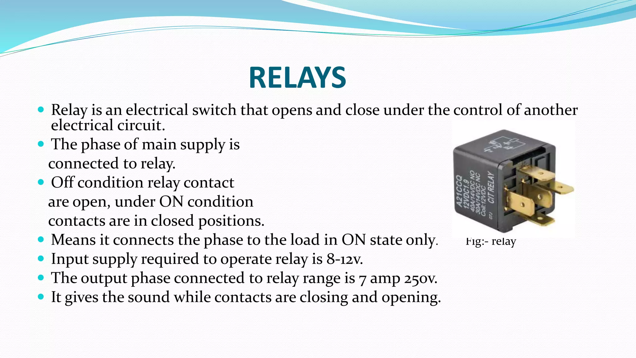
RELAYS
Relay isan electrical switch that opens and close under the control of another
electrical circuit.
The phase of main supply is
connected to relay.
Off condition relay contact
are open, under ON condition
contacts are in closed positions.
Means it connects the phase to the load in ON state only. Fig:- relay
Input supply required to operate relay is 8-12v.
The output phase connected to relay range is 7 amp 250v.
It gives the sound while contacts are closing and opening.
13.
AUXILIARY COMPONENTS
Led lightsare used to know the circuit status, means
power in the circuit is present or not.
Reset switch is used for restart the controller tasks
from the beginning when ever it is struck.
Crystal oscillator is used to generate the proper
voltage to relays in controller (means generating
clock pulses).
14.
Benefits to utilities:-
Upfront payment of electricity.
Lower overheads.
No billing hassles.
No disconnection/reconnection.
Temper and fraud detection.
Time and money based connection and disconnection.
Load/demand control.
15.
Benefit to cousumers:-
Payas you go.
No need to stand in queues.
No surprising bills.
No bill disputes.
Allow costumer to budget expences.
Helps costumer towards energy conservations
16.
FUTURE SCOPE
Amini printer can be interfaced to get a printed bill
or details of billing.
Remote charging can be implemented through
telephone line or wireless network.
Software can be modified to view the balance on
request.
17.
CONCLUSION
This project isperforming satisfactory function in
laboratory conditions. The device designed is used
in conjunction with an Induction Energy meter.
With minor modification in software and hardware
this system can be used for field applications.