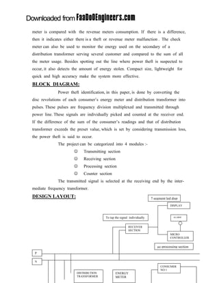
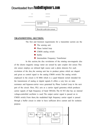
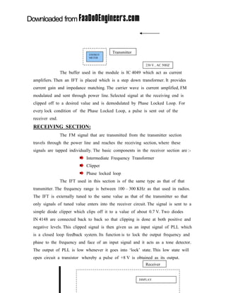
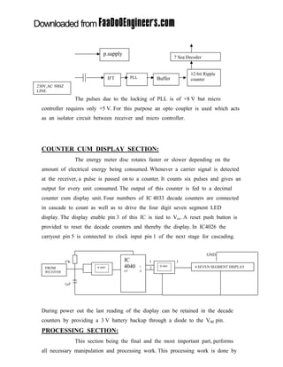
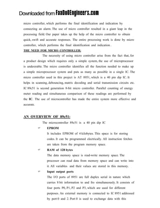
SlideShare a Scribd company logo
1 of 16
Download to read offline
101seminartopics.com


ABSTRACT


               Science and technology with all its miraculous advancements has
fascinated human life to a great extent that imagining a world without these
innovations is hardly possible. While technology is on the raising slope, we
should also note the increasing immoral activities. With a technical view, ā€œPower
Theftā€ is a non-ignorable crime that is highly prevalent, and at the same time it
directly affects the economy of a nation. Data collected over Tirunelveli District,
Bhel Trichy proves the necessity of this project.
                Detecting and eradicating such crimes with the assistance of the
developing scientific field is the ā€œNeed of the Hourā€. With these views was this
paper conceived and designed. Our paper provides a complete and comprehensive
tool to prevent power theft which is very simple to understand and easy to
implement(Accepted by T.N.E.B officials). It includes four sections ā€“ transmitting,
receiving, counter display and processing sections.
DESCRIPTION OF OUR IMPLEMENTATION IDEAS:

               The disc revolutions are sensed into pulses by optical slot sensor.
These pulses are shaped and given as control signal to the CMOS switch which
bypasses carrier wave generated by PLL provides as input to receiving section
where transmitted signal is selected by the Intermediate frequency transformer. For
each lock a pulse is sent out. The counter section is designed to send out pulse for
every six input pulse from the receiver section. This count is parallely distributed
in a 7-segmentdisplay and then to Āµc for further processing. Āµc performs the
function of indication and identification. Pindetails, features, connections and software
employed for Āµc89c51 are described in detail.
               We believe our implementation ideas is a boon to the electricity
board offering them a chance to detect accurately the location and amount of
power theft. Logical view for a digital meter is also included in our presentation.
101seminartopics.com


INTRODUCTION:
       ā€œTODAYā€™S TECHNICIANS ARE SO FOCUSSED ON THE TREES OF TECHNOLOGICAL
       CHANGE THAT THEY FAIL TO SEE THE FOREST; THE UNDERLYING ECONOMIC
       FORCES THAT DETERMINE SUCCESS AND FAILUREā€¦ā€
                ā€œTECHNOLOGY CHANGES ECONOMY LAWS DO NOTā€

              Electricity is the modern manā€™s most convenient and useful form of
energy without which the present social infrastructure would not be feasible. The
increase in per capita production is the reflection of the increase in the living
standard of people. When importance of electricity is on the increasing side, then
how much should theft of this energy or illegal consumption of power from the
transmission lines be averted? Power theft has become a great challenge to the
electricity board. The dailies report that Electricity Board suffers a total loss of
8 % in revenue due to power theft every year, which has to controlled. Our paper
identifies the Power theft and indicates it to the Electricity board through Power
line. We had also dealt about the remote monitoring of an energy meter.
MICROCONTROLLER BASED AUTOMATION:
              Embedded systems - a combination of software, hardware and
additional mechanical parts that together forms a component of a larger system, to
perform a specific function. Itā€™s a technology, characterized by high reliability,
restricted memory footprint and real time operation associated with a narrowly
defined group of functions. Automation has made the art of living comfortable and
easy. Embedded systems have made the process of automation a most successful
one. Here, we have focused on automotive, an area of embedded controllers, in
which we have dealt with the Power theft identification and also about the remote
monitoring of an energy meter.

          ā€œTechnology have taken the world by storm
          performance ratings and exceptionally value for money pricesā€


The microcontroller chip is preprogrammed to perform a dedicated or a narrow
range of functions as a part of a larger system, usually with minimal end user or
101seminartopics.com

operator intervention. Our paper throws light on automated monitoring of theft
identification, which is an application of embedded controllers.


MODES OF THEFT:
                 It has been seen that there are 4 common methods of power
theft as given below :-
                          Bogus seals and tampering of seals.
                          Meter tampering, meter tilting, meter interface and
                          meter bypassing.
                          Changing connection.
                          Direct tapping from line.
              Due to introduction of modern electronic metering equipments, power
thieves are utilizing more technological methods. Recent cases of power theft
discovered by British inspectors included customers tunneling out to roadside
mains cables and splicing into the supply, a garage taking its night time power
supply from the nearest lamp post and domestic customers drilling holes into
meter boxes and attempting to stop the counter wheels from turning. Another
method of Power theft is by keeping a strong magnet in front of the disc in
the energy meter and thus arresting the rotation of the disc, connecting the load
directly to the power line bypassing the energy meter. But, it can be avoided
easily by providing a non magnetic enclosure.
MODERN DETECTING TOOLS:
             There are many modern tools that assist in power theft identification.
Some of them are :-
                          ļƒ¼   Tamper proof seals and labels.
                          ļƒ¼   Meter leaders.
                          ļƒ¼   Tamper resistant screws / locks.
                          ļƒ¼   Check meter and remote meter readers.
                          ļƒ¼   Tamper alarms and sensors.
              This paper undertakes the Check meter and remote meter readers for
power theft identification. In our case, the consumption recurred by the check
101seminartopics.com

meter is compared with the revenue meters consumption. If there is a difference,
then it indicates either there is a theft or revenue meter malfunction . The check
meter can also be used to monitor the energy used on the secondary of a
distribution transformer serving several customer and compared to the sum of all
the meter usage. Besides spotting out the line where power theft is suspected to
occur, it also detects the amount of energy stolen. Compact size, lightweight for
quick and high accuracy make the system more effective.
BLOCK DIAGRAM:
              Power theft identification, in this paper, is done by converting the
disc revolutions of each consumerā€™s energy meter and distribution transformer into
pulses. These pulses are frequency division multiplexed and transmitted through
power line. These signals are individually picked and counted at the receiver end.
If the difference of the sum of the consumerā€™s readings and that of distribution
transformer exceeds the preset value, which is set by considering transmission loss,
the power theft is said to occur.
              The project can be categorized into 4 modules :-
                       ļŠ    Transmitting section
                       ļŠ    Receiving section
                       ļŠ    Processing section
                       ļŠ    Counter section
              The transmitted signal is selected at the receiving end by the inter-
mediate frequency transformer.
DESIGN LAYOUT:                                                           7 segment led disp
                                                                                      DISPLAY


                                        To tap the signal individually                  ALARM


                                                         RECEIVER
                                                         SECTION
                                                                                      MICRO
                                                                                      CONTROLLER


                                                                             Āµc-processing section
 P

 N
                                                                               CONSUMER
                                                                               NO:1
                        DISTRIBUTION           ENERGY
                        TRANSFORMER            METER
101seminartopics.com


                                                                       CONSUMER
                                                                       NO:2
                            TRANSMITTER
                            SECTION


                            Provide with slot sensor


TRANSMITTING SECTION:
              The first and foremost requirements for a transmitter section are the
                            The sensing unit
                            Phase locked loop
                            CMOS analog switch
                            Buffer
                            Intermediate Frequency Transformer
              In this section, the disc revolutions of the rotating non-magnetic disc
of the electro magnetic energy meter are sensed by opto coupler slot sensor. This
slot sensor employs an infrared light source and a photo detector. For each
revolution of the disc, the sensing unit has to produce pulses which are shaped
and given as control signal to the analog CMOS switch. The analog switch
employed in the circuit is IC 4066 which is a quad bilateral switch intended for
the transmission of analog or digital signals. It offers a very low on state
resistance and bypasses carrier wave generated by Phase Locked Loop to the next
part of the circuit. Here, PLL acts as a carrier signal generator, which produces
carrier signals of high frequency of band 300 kHz. The IC 567, that has an internal
voltage-controlled oscillator is used. The output carrier signal is passed on to
CMOS switch. From there, the modulated high frequency carrier signal is passed
through a buffer circuit in order to have sufficient drive current and for isolation
purpose.


                              Analog.sw


                   PLL                    BUF          IFT
                                          FER

                                                P.SUPPLY
101seminartopics.com


                               ENERGY
                                           Transmitter
                               METER

                                                            230 V , AC 50HZ

                The buffer used in the module is IC 4049 which act as current
amplifiers. Then an IFT is placed which is a step down transformer. It provides
current gain and impedance matching. The carrier wave is current amplified, FM
modulated and sent through power line. Selected signal at the receiving end is
clipped off to a desired value and is demodulated by Phase Locked Loop. For
every lock condition of the Phase Locked Loop, a pulse is sent out of the
receiver end.
RECEIVING SECTION:
                The FM signal that are transmitted from the transmitter section
travels through the power line and reaches the receiving section, where these
signals are tapped individually. The basic components in the receiver section are :-
                             Intermediate Frequency Transformer
                             Clipper
                             Phase locked loop
                The IFT used in this section is of the same type as that of that
transmitter. The frequency range is between 100 ā€“ 300 KHz as that used in radios.
The IFT is externally tuned to the same value as that of the transmitter so that
only signals of tuned value enters into the receiver circuit. The signal is sent to a
simple diode clipper which clips off it to a value of about 0.7 V. Two diodes
IN 4148 are connected back to back so that clipping is done at both positive and
negative levels. This clipped signal is then given us an input signal of PLL which
is a closed loop feedback system. Its function is to lock the output frequency and
phase to the frequency and face of an input signal and it acts as a tone detector.
The output of PLL is low whenever it goes into ā€˜lockā€™ state. This low state will
open circuit a transistor whereby a pulse of +8 V is obtained as its output.
                                                            Receiver


                                                         DISPLAY
101seminartopics.com


                                   p.supply
                                                                           7 Seg.Decoder


                                                                                  12-bit Ripple
                                        IFT        PLL           Buffer           counter
230V,AC 50HZ
LINE
                      The pulses due to the locking of PLL is of +8 V but micro
  controller requires only +5 V. For this purpose an opto coupler is used which acts
  as an isolator circuit between receiver and micro controller.


  COUNTER CUM DISPLAY SECTION:
                      The energy meter disc rotates faster or slower depending on the
  amount of electrical energy being consumed. Whenever a carrier signal is detected
  at the receiver, a pulse is passed on to a counter. It counts six pulses and gives an
  output for every unit consumed. The output of this counter is fed to a decimal
  counter cum display unit. Four numbers of IC 4033 decade counters are connected
  in cascade to count as well as to drive the four digit seven segment LED
  display. The display enable pin 3 of this IC is tied to Vcc. A reset push button is
  provided to reset the decade counters and thereby the display. In IC4026 the
  carryout pin 5 is connected to clock input pin 1 of the next stage for cascading.


                                                                                           GND
               47K                            IC             1              3
   FROM                        IC4093         4040       7   2
                                                                  IC4081            4 SEVEN SEGMENT DISPLAY
   RECEIVER                                   CP         6


               .1ĀµF


  During power out the last reading of the display can be retained in the decade
  counters by providing a 3 V battery backup through a diode to the Vdd pin.
  PROCESSING SECTION:
                      This section being the final and the most important part, performs
  all necessary manipulation and processing work. This processing work is done by
101seminartopics.com

micro controller, which performs the final identification and indication by
connecting an alarm. The use of micro controller resulted in a giant leap in the
processing field. Our paper takes up the help of the micro controller to obtain
quick, swift and accurate responses. The entire processing work is done by micro
controller, which performs the final identification and indication .
THE NEED FOR MICRO CONTROLLER:
                The necessity of using micro controller arise from the fact that, for
a product design which requires only a simple system, the use of microprocessor
is undesirable. The micro controller identifies all the function needed to make up
a simple microprocessor system and puts as many as possible in a single IC. The
micro controller used in this project is AT 8951, which is a 40 pin dip IC. It
helps in scanning, debouncing, matrix decoding and serial transmission circuits etc.
IC 89c51 is second generation 8-bit micro controller. Parallel counting of energy
meter reading and simultaneous comparison of these readings are performed by
the IC. The use of microcontroller has made the entire system more effective and
accurate.


AN OVERVIEW OF 89c51:
                The microcontroller 89c51 is a 40 pin dip IC
            ļ†      EPROM
                   It includes EPROM of 4 kilobytes. This space is for storing
                   codes. It can be programmed electrically. All instruction fetches
                   are taken from the program memory space.
            ļ†      RAM of 128 bytes
                   The data memory space is read-write memory space. The
                   processor can read data from memory space and can write into
                   it. All variables and their values are stored in this memory.
            ļ†      Input output ports
                   The I/O ports of 8951 are full duplex serial in nature which
                   carries 8 bit information to and fro simultaneously. It consists of
                   four ports P0, P1, P2 and P3, which are used for different
                   purposes. An external memory is connected to IC 8951 addressed
                   by port 0 and 2. Port 0 is used to exchange data with this
101seminartopics.com

                  memory with the help of multiplexed address data bus. Port 3 is
                  used to perform external data memory WRITE and READ
                  functions.
              The entire programming in the controller is looked after by the
instruction set. The IC 8951 instruction set has 50 instructions, which can be
summarized as data transfer instructions, multiplication, division, call, jump etc.
Comparing the instruction set of a general purpose 8-bit microprocessor, itā€™s
obvious that in some ways it has more power or in other words the micro
controller has some real imitations. The major demerit is the availability of
limited stack which can be extended by connecting external memory to it.
Power saving modes:
              It is designed when static logic for operation down to zero
frequency and supports two software selectable power saving modes,
     ļ‚— IDLE mode stops the CPU while allowing the RAM, the timer/counter,
         serial port and Interrupt system to continue functioning.
     ļ‚— POWER DOWN mode saves the RAM contents but freezes the oscillator,
         disabling all other functions until the next hardware reset.


     PIN DIAGRAM OF IC 89C51:
101seminartopics.com


                                                     PORT 1 & 3 (1-8,10-17)
                                                              A 8-BIT BI-DIRECTIONAL I/O
                                                     PORT WITH INTERNAL PULL-UPS. IT
                                                     RECEIVES LOWER ORDER ADDRESS

                                                     BYTES DURING FLASH PROGRAMMING.

                                                     PORT O (32-39)
                                                              A 8-BIT BI-DIRECTIONAL I/O
                                                     PORT. IT IS CONFIGURED TO BE THE
                                                     MULTIPLEXED LOW ORDER
                                                     ADDRESS/DATA BUS DURING ACCESSES
                                                     TO EXTERNAL PROGRAM AND DATA
                                                     MEMORY.
                                                     PORT 2 (21-28)
                                                              IT PERFORMS THE SAME
                                                     FUNCTION AS THE PORT 1 INADDITION
                                                     IT RECEIVES SOME CONTROL SIGNALS
                                                     DURING FLASH PROGRAMMING AND

OPERATION OF MICRO CONTROLLER:
                    The different connections are shown in the design layout. The
set value can be given through port P1 by means of DIP switches. The possible
values can be set by it.
                     The pulses from each energy meter after being received is
given as input individually to pin 12 & 13 and 16 of port 3.
                    The frequency of operation of the controller can be varied by
choosing crystal of desired value. The ceramic crystal is connected across 18th and
19th pin of the IC 8951. High frequency of about 8 MHz is chosen.
                    Power theft identification is done by means of an alarm,
which is connected to the 39th pin of IC. Once the alarm is set on, the resetting
of the controller can be done by connecting a push button to pin 9.
                    It can be noted that the other pins of the ICs are unused
and hence no connection are given to them. As the program written occupies
space less than is 4 kbytes, no external memory is used hence 31st pin is made
high.
                     The program is written and is down loaded to the IC 8751
by means of PC. The program is written so as to assign the function of each pin.
101seminartopics.com

Also it initials continuous counting of units and simultaneous comparison. If error
is predicted the buzzer is made to give alarm signal.


SOFTWARE DESCRIPTION FOR IC 89C51:
The program for 89c51 is shown in this section. We present it in the form of
several blocks to make it more clear and easily readable.
101seminartopics.com


  INITIALISING THE PARAMETERS                CHECKING THE SEVENTH CONDITION


  0016 75DOE7          MOV PSW,#0E7H
                                            0079 7C24         CK.FOR.7
  0019 7581FS          MOV SO,#SFH
                                            007B 020086       MOV KEY.SET.REG,#036D
  001C 758000          MOV P0,#00H
                                            007E BC0705       JMP CHECK.DIFF
  001F 7590FF          MOV P1,$OFFH
                                            0081    7C2A    CJNE KEY.SET.REG,#007H,CHE
  0022 75A000          MOV P2,#00H
  0025 75B0FF          MOV P3,#00FH


  INITIALISING THE PULSE REGISTERS          CHECK DIFFERENCE FOLLOWED BY ALARM
                                            0083     020086     CK.DIFF
  0028 7800       MOV PULSE.1.REG,#00H      0086                 MOV KEY.SET.REG,#420

  002A 7900       MOV PULSE.2.REG,#00H      0086     EB          JMP CHECK.DIFF
  002C 7A00     MOV PULSE.3.REG,#00H        0087     C3          MOV R,RES.REG
  002E D288     SETB IT0                    0088     9C          CLR C
  0030   D28A SETB IT1                      0089     5110        SUBB AMKEY.SET.REG
                                            008B     8BAO        JNC SET.ALARM


  EXECUTION OF CHECKING CONDITON
  (CHECKING FIRST CONDITION)
  0047   98         SUBB A,PULSE.1.REG      FREQUENT LOOPING OF AN ALARM CKT

  0048   FB         MOV RES.REG,A
  0049   E590       MOV A,P1PULSE.1.REG      008D    80AF         MOV P2,RES.REG

  004B   54OF       ANL A,#00001111B         008F                 JMP X1

  004D   FC         MOV KEY.SET.REG,A        008F C2A8            CLR EXO

  004E BC0105 CJNE KEY.SET.REG,#001H,CHE     0091    08           INC PULSE.1.REG
                                             0092    D2A8         SETB EXO
                                             0094    32           RET1
                                             0095    C2AA
  EXECUTION OF SECOND CHECKING
                                             0097 D2              INC
  CONDITON
                                             0098 AA             SETB
  0051   7C06       CK.FOR.2
                                             009A                 RETI
  0053   020086     MOV KEY.SET.REG,#006H
  0056              JMP CHECK.DIFF
  0056 BC0205CJNE KEY.SET.REG,#002H,CHE
101seminartopics.com


   EXECUTION OF THIRD CHECKING CONDITION                OPCODE TO DIRECT AN ALARM


   0059   7COC     CH.FOR.3                             009B   8BAO       MOV P2,RES.REG
   005B   020086   MOV KEY.SET.REG,#012                 009D   D280       SETB ALARM.PIN
   005E            CHECK.DIFF                           009F   C2A8        CLR EX0
   005E   BC0305 CJNE KEY.SET.REG,#003H,CHE             00A1   C2AA       CLR EX1
                                                        00A3   80F6        JMP SET.ALARM


The execution of first three and last conditions are shown here. Other conditions
are executed in a similar way.

The process will be executed and the Āµ c enables simple, cost effective ,accurate
and much more reliable system. Itā€™s high frequency enables all the pulses without
missing any.
MONITORING MEASURES:
     ļ€ŗ The display need not be kept always on, and can be powered up using a
          push switch whenever required to note down the reading.
     ļ€ŗ Protection against high voltage on the transmitter or receiver is possible
          by the usage of special high voltage suppressers like gas discharge tubes
          provided with a coupling point with fuses to disconnect the respective
          transmitter or receiver.
     ļ€ŗ Distance coverage is an important limitation which can be overcome by
          providing the repeaters at regular intervals when applied in a large scale.
     ļ€ŗ The display need not be kept always on, and can be powered up using a
          push switch whenever required to note down the reading.
     ļ€ŗ Effects of PF improvement capacitors on the line and distribution
          transformers may interfere with the message signal or the effect of
          atmospheric noises is to be analyzed before implementing in a large scale.
MERITS:
                       Due to the availability of digital energy meter, this
                       implementation can be easily performed for power theft
                       identification.
                       Highly accurate, low loss and economical one.
101seminartopics.com

                     Our implementation may gives a big hand to vigilance squad
                     to control theft quickly and easily
                     Using this same logic, instead of micro controller we can
                     adapt computer for more number of uses
                     In day-to-day conventional methods, itā€™s possible to identify
                     the theft but the extent of theft cannot be identified but itā€™s
                     possible with our Check meter and remote meter readers.
                     Compact size, Reliability, lightweight for quick operation and
                     high accuracy makes the system more effective.
                     Maintenance ā€“ holds more value than construction. In our case,
                     cost is very less, it involves the planned serving of equipment
                     at regular interval. Emergency maintenance is the case when
                     the maintenance crew due to repair of any sections can be
                     succeeded by,
                            A rational spare parts policy.
                            A maintenance staff of highly skilled, highly trained
                            personnel.
CONCLUDING LINES:
      ā€œWhen you donā€™t have a thing to worry about, those signs of
         age will stay away. Itā€™s just dumping obsolete technology
                        with no peace of mindā€

              This paper is designed for industrial purpose, but it can be extended
to domestic purposes also. It gives a big hand to vigilance squad to control theft
quickly and easily. With its usage, the crime of stealing power may be brought to
an end and thereby a new bloom may be expected in the economy of our
motherland. The prime limitation of the system in the present form is the distance
coverage. To overcome this when applied in a large scale, repeaters can be
employed at suitable intervals. To certain extent the power level of the transmitter
may be improved. Our paper not only indicates the place of power theft but also
the amount of energy being stolen that is, it gives the best of the expected results.
The use of this technique gives a new hope and accuracy for the satisfaction to
complete the work.
101seminartopics.com


               TAMIL NADU ELECTRICITY BOARD
                        Tirunelveli urban division

                     Lt line loss study for the period form 5.2.2002 to 20.2.2002
SI.NO     NAME OF THE       NAME OF DIST.    CONSUMPTION     CONSUMPTION     LOSS IN      LOSS
          SECTION           TRANSFORMER      AT THE          AT THE          UNITS        IN
                                             TRANSFORMER     CONSUMER
                                             END             END
                                                                                            %

   1.     JUNCTION          TAMILNADU          3116 UNITS      2975 UNITS    141 UNITS    4.5%
                            HOTEL SS
   2.     MAHARAJANAGAR     SAVAI ILLAM SS     4010 UNITS      3599 UNITS    411 UNITS    10.24
                                                                                          %
   3.     MELAPALAYAM       KALIAMMANKOIL      8936 UNITS      8086 UNITS    850 UNITS    9.5%
                            SS
   4.     PALAYAPETTAI      ABISEKAPATTI       1840 UNITS      1538 UNITS    302 UNITS    16.41
                            63KVA                                                         %
   5.     PETTAI            MALAYALAMEDU       11552 UNITS     9520 UNITS    2032 UNITS   17.5%

   6.     THACHANALLUR      KATTUDIYAR         291 UNITS       5942 UNITS    METER
                            KUDIRUPPU                                        DEFECT
   7.     V.M.CHATRAM       TNHB SS V100       4583 UNITS      4450 UNITS    133 UNITS    2.9%

   8.     SAMATHANAPURAM    MADIKONDU SS       6841 UNITS      6674 UNITS    167 UNITS    2.44%
                            100 KVA
   9.     VANNARPETTAI      MURUGANKURICHI     8678 UNITS      8402 UNITS    271 UNITS    3.12%
                            33 III 100KVA
101seminartopics.com

`
                  TRANSFORMER LOSS FOR DTā€™s:


     LOSS IN DTā€™s=(TOTAL COPPER LOSS+TOTAL IRON LOSS)/1000


    STATEMENT SHOWING THE TRANSFORMER LOSS FOR VARIOUS OF DISTRIBUTION
                          TRANSFORMERS
                   DISTRIBUTION          MAX. IRON        MAX. COPPER
      SI.NO        TRANSFORMER          LOSS(WATTS)       LOSS(WATTS)

      1.              63KVA/11KV          180               1235

      2.              63KVA/22KV          210               1300

      3.              100KVA/11KV         260               1760

More Related Content

What's hot

Smart Meters
Smart MetersSmart Meters
Smart MetersDr K M SONI
Ā 
Automatic energy meter reading
Automatic energy meter readingAutomatic energy meter reading
Automatic energy meter readingSURYAANDUKURI
Ā 
Power theft detection
Power theft detectionPower theft detection
Power theft detectionbishow kandel
Ā 
Wireless power-theft-monitering-ppt
Wireless power-theft-monitering-pptWireless power-theft-monitering-ppt
Wireless power-theft-monitering-pptArjit Rajwal
Ā 
PROJECT REPORT
PROJECT REPORTPROJECT REPORT
PROJECT REPORTShivarajaDM
Ā 
Smart grid and micro grid
Smart grid and micro gridSmart grid and micro grid
Smart grid and micro gridPurna chandar
Ā 
Ppt power theft identification and detection using gsm
Ppt power theft identification and detection using gsmPpt power theft identification and detection using gsm
Ppt power theft identification and detection using gsmradha krishna
Ā 
Smart Grid : A state of art
Smart Grid : A state of artSmart Grid : A state of art
Smart Grid : A state of artJitendra kapoor
Ā 
Wireless power theft monitoring
Wireless power theft monitoring Wireless power theft monitoring
Wireless power theft monitoring Naqeeb Ullah Kakar
Ā 
Smart energy meter ppt
Smart energy meter   pptSmart energy meter   ppt
Smart energy meter pptRitam Giri
Ā 
Seminar presentation on Smart Energy Meter
Seminar presentation on Smart Energy MeterSeminar presentation on Smart Energy Meter
Seminar presentation on Smart Energy Metersudhanshurj
Ā 
AUTOMATIC METER READING BY SAIKIRAN PANJALA
AUTOMATIC METER READING BY SAIKIRAN PANJALAAUTOMATIC METER READING BY SAIKIRAN PANJALA
AUTOMATIC METER READING BY SAIKIRAN PANJALASaikiran Panjala
Ā 
Intelligent Substation & its applications
Intelligent Substation & its applicationsIntelligent Substation & its applications
Intelligent Substation & its applicationsGowtham MG
Ā 
Web based power quality monitoring system
Web based power quality monitoring systemWeb based power quality monitoring system
Web based power quality monitoring systemVikram Purohit
Ā 
AUTOMATIC ENERGY METER READING SYSTEM FOR BILLING PURPOSE
AUTOMATIC ENERGY METER READING SYSTEM FOR BILLING PURPOSEAUTOMATIC ENERGY METER READING SYSTEM FOR BILLING PURPOSE
AUTOMATIC ENERGY METER READING SYSTEM FOR BILLING PURPOSEBitan Das
Ā 
Wireless Power Transfer
Wireless Power TransferWireless Power Transfer
Wireless Power TransferSaumyadip Moitra
Ā 

What's hot (20)

Smart Meters
Smart MetersSmart Meters
Smart Meters
Ā 
Automatic energy meter reading
Automatic energy meter readingAutomatic energy meter reading
Automatic energy meter reading
Ā 
Power theft detection
Power theft detectionPower theft detection
Power theft detection
Ā 
Wireless power-theft-monitering-ppt
Wireless power-theft-monitering-pptWireless power-theft-monitering-ppt
Wireless power-theft-monitering-ppt
Ā 
PROJECT REPORT
PROJECT REPORTPROJECT REPORT
PROJECT REPORT
Ā 
Smart grid and micro grid
Smart grid and micro gridSmart grid and micro grid
Smart grid and micro grid
Ā 
Ppt power theft identification and detection using gsm
Ppt power theft identification and detection using gsmPpt power theft identification and detection using gsm
Ppt power theft identification and detection using gsm
Ā 
Smart Grid : A state of art
Smart Grid : A state of artSmart Grid : A state of art
Smart Grid : A state of art
Ā 
Wireless power theft monitoring
Wireless power theft monitoring Wireless power theft monitoring
Wireless power theft monitoring
Ā 
Smart energy meter ppt
Smart energy meter   pptSmart energy meter   ppt
Smart energy meter ppt
Ā 
Seminar presentation on Smart Energy Meter
Seminar presentation on Smart Energy MeterSeminar presentation on Smart Energy Meter
Seminar presentation on Smart Energy Meter
Ā 
Automatic meter reading
Automatic meter readingAutomatic meter reading
Automatic meter reading
Ā 
AUTOMATIC METER READING BY SAIKIRAN PANJALA
AUTOMATIC METER READING BY SAIKIRAN PANJALAAUTOMATIC METER READING BY SAIKIRAN PANJALA
AUTOMATIC METER READING BY SAIKIRAN PANJALA
Ā 
Intelligent Substation & its applications
Intelligent Substation & its applicationsIntelligent Substation & its applications
Intelligent Substation & its applications
Ā 
Web based power quality monitoring system
Web based power quality monitoring systemWeb based power quality monitoring system
Web based power quality monitoring system
Ā 
AUTOMATIC ENERGY METER READING SYSTEM FOR BILLING PURPOSE
AUTOMATIC ENERGY METER READING SYSTEM FOR BILLING PURPOSEAUTOMATIC ENERGY METER READING SYSTEM FOR BILLING PURPOSE
AUTOMATIC ENERGY METER READING SYSTEM FOR BILLING PURPOSE
Ā 
Smart grid
Smart  gridSmart  grid
Smart grid
Ā 
Wireless Power Transfer
Wireless Power TransferWireless Power Transfer
Wireless Power Transfer
Ā 
Prepaid energymeter
Prepaid energymeterPrepaid energymeter
Prepaid energymeter
Ā 
KSEB Training Reporty
KSEB Training ReportyKSEB Training Reporty
KSEB Training Reporty
Ā 

Viewers also liked

Electricity theft (1)
Electricity theft (1)Electricity theft (1)
Electricity theft (1)sharique_64
Ā 
Wireless power theft monitoring
Wireless power theft monitoringWireless power theft monitoring
Wireless power theft monitoringBiswajit Pratihari
Ā 
energy theft detection
energy theft detectionenergy theft detection
energy theft detectionabdulsuboor235
Ā 
Intelligent Electric Power Management Using Zigbee with Advanced Metering Inf...
Intelligent Electric Power Management Using Zigbee with Advanced Metering Inf...Intelligent Electric Power Management Using Zigbee with Advanced Metering Inf...
Intelligent Electric Power Management Using Zigbee with Advanced Metering Inf...Akbar Badusha
Ā 
PLC and Sensors Based Protection and Fault Detection of Induction Motors
PLC and Sensors Based Protection and Fault Detection of Induction MotorsPLC and Sensors Based Protection and Fault Detection of Induction Motors
PLC and Sensors Based Protection and Fault Detection of Induction MotorsMathankumar S
Ā 
Microcontroller based-substation-monitoring-and-controlling-system
Microcontroller based-substation-monitoring-and-controlling-systemMicrocontroller based-substation-monitoring-and-controlling-system
Microcontroller based-substation-monitoring-and-controlling-systemMahmud Hasan Uday
Ā 
(Aliv) Multiple Transformers Oil Temperature Monitoring with Automatic Circui...
(Aliv) Multiple Transformers Oil Temperature Monitoring with Automatic Circui...(Aliv) Multiple Transformers Oil Temperature Monitoring with Automatic Circui...
(Aliv) Multiple Transformers Oil Temperature Monitoring with Automatic Circui...Md Abu Jauad Khan Aliv
Ā 
SINGLE PHASING, PHASE REVERSAL, OVERVOLTAGE, UNDER VOLTAGE AND OVERHEATING PR...
SINGLE PHASING, PHASE REVERSAL, OVERVOLTAGE, UNDER VOLTAGE AND OVERHEATING PR...SINGLE PHASING, PHASE REVERSAL, OVERVOLTAGE, UNDER VOLTAGE AND OVERHEATING PR...
SINGLE PHASING, PHASE REVERSAL, OVERVOLTAGE, UNDER VOLTAGE AND OVERHEATING PR...Michael George
Ā 
final_report
final_reportfinal_report
final_reportRahul Roshan
Ā 
GSM BASED PREPAID ENERGY METER BILLING VIA SMS
GSM BASED PREPAID ENERGY METER BILLING VIA SMSGSM BASED PREPAID ENERGY METER BILLING VIA SMS
GSM BASED PREPAID ENERGY METER BILLING VIA SMSSRINIVAS REDDY
Ā 
Microcontroller Programming Assignment
Microcontroller Programming AssignmentMicrocontroller Programming Assignment
Microcontroller Programming Assignmentbabak danyal
Ā 
Connecting your building's meters to energy management software
Connecting your building's meters to energy management softwareConnecting your building's meters to energy management software
Connecting your building's meters to energy management softwarePulse Energy
Ā 
Project paper
Project paperProject paper
Project paperchigongo
Ā 
Identity theft power_point
Identity theft power_pointIdentity theft power_point
Identity theft power_pointefandeye
Ā 
AMI-Presentation
AMI-PresentationAMI-Presentation
AMI-PresentationDuaa Shoukat
Ā 
Report File On RedTacton
Report File On RedTactonReport File On RedTacton
Report File On RedTactonRajendra Dangwal
Ā 
Dcā€“Dc converters
Dcā€“Dc convertersDcā€“Dc converters
Dcā€“Dc convertersBhulku Kalpak
Ā 

Viewers also liked (20)

Electricity theft (1)
Electricity theft (1)Electricity theft (1)
Electricity theft (1)
Ā 
Wireless power theft monitoring
Wireless power theft monitoringWireless power theft monitoring
Wireless power theft monitoring
Ā 
Power theft
Power theftPower theft
Power theft
Ā 
energy theft detection
energy theft detectionenergy theft detection
energy theft detection
Ā 
Intelligent Electric Power Management Using Zigbee with Advanced Metering Inf...
Intelligent Electric Power Management Using Zigbee with Advanced Metering Inf...Intelligent Electric Power Management Using Zigbee with Advanced Metering Inf...
Intelligent Electric Power Management Using Zigbee with Advanced Metering Inf...
Ā 
PLC and Sensors Based Protection and Fault Detection of Induction Motors
PLC and Sensors Based Protection and Fault Detection of Induction MotorsPLC and Sensors Based Protection and Fault Detection of Induction Motors
PLC and Sensors Based Protection and Fault Detection of Induction Motors
Ā 
Microcontroller based-substation-monitoring-and-controlling-system
Microcontroller based-substation-monitoring-and-controlling-systemMicrocontroller based-substation-monitoring-and-controlling-system
Microcontroller based-substation-monitoring-and-controlling-system
Ā 
(Aliv) Multiple Transformers Oil Temperature Monitoring with Automatic Circui...
(Aliv) Multiple Transformers Oil Temperature Monitoring with Automatic Circui...(Aliv) Multiple Transformers Oil Temperature Monitoring with Automatic Circui...
(Aliv) Multiple Transformers Oil Temperature Monitoring with Automatic Circui...
Ā 
SINGLE PHASING, PHASE REVERSAL, OVERVOLTAGE, UNDER VOLTAGE AND OVERHEATING PR...
SINGLE PHASING, PHASE REVERSAL, OVERVOLTAGE, UNDER VOLTAGE AND OVERHEATING PR...SINGLE PHASING, PHASE REVERSAL, OVERVOLTAGE, UNDER VOLTAGE AND OVERHEATING PR...
SINGLE PHASING, PHASE REVERSAL, OVERVOLTAGE, UNDER VOLTAGE AND OVERHEATING PR...
Ā 
final_report
final_reportfinal_report
final_report
Ā 
GSM BASED PREPAID ENERGY METER BILLING VIA SMS
GSM BASED PREPAID ENERGY METER BILLING VIA SMSGSM BASED PREPAID ENERGY METER BILLING VIA SMS
GSM BASED PREPAID ENERGY METER BILLING VIA SMS
Ā 
Microcontroller Programming Assignment
Microcontroller Programming AssignmentMicrocontroller Programming Assignment
Microcontroller Programming Assignment
Ā 
Connecting your building's meters to energy management software
Connecting your building's meters to energy management softwareConnecting your building's meters to energy management software
Connecting your building's meters to energy management software
Ā 
Tech seminar
Tech seminarTech seminar
Tech seminar
Ā 
Project paper
Project paperProject paper
Project paper
Ā 
Synopsis
SynopsisSynopsis
Synopsis
Ā 
Identity theft power_point
Identity theft power_pointIdentity theft power_point
Identity theft power_point
Ā 
AMI-Presentation
AMI-PresentationAMI-Presentation
AMI-Presentation
Ā 
Report File On RedTacton
Report File On RedTactonReport File On RedTacton
Report File On RedTacton
Ā 
Dcā€“Dc converters
Dcā€“Dc convertersDcā€“Dc converters
Dcā€“Dc converters
Ā 

Similar to Micro controller-based-power-theft-identification

IRJET- Wireless Power Theft Monitoring System using Zigbee
IRJET- Wireless Power Theft Monitoring System using ZigbeeIRJET- Wireless Power Theft Monitoring System using Zigbee
IRJET- Wireless Power Theft Monitoring System using ZigbeeIRJET Journal
Ā 
A Smart Handheld Measuring and Testing Electronic Device with Touch Screen
A Smart Handheld Measuring and Testing Electronic Device with Touch ScreenA Smart Handheld Measuring and Testing Electronic Device with Touch Screen
A Smart Handheld Measuring and Testing Electronic Device with Touch ScreenIJTET Journal
Ā 
24. deepti semwal.pptx
24. deepti semwal.pptx24. deepti semwal.pptx
24. deepti semwal.pptxSnehdeep Kunwar
Ā 
IRJET- Electricity Theft Monitoring and its Consumption Savings
IRJET- Electricity Theft Monitoring and its Consumption SavingsIRJET- Electricity Theft Monitoring and its Consumption Savings
IRJET- Electricity Theft Monitoring and its Consumption SavingsIRJET Journal
Ā 
Tracking and breaking system for vehicles
Tracking and breaking system for vehiclesTracking and breaking system for vehicles
Tracking and breaking system for vehicleskakanikings
Ā 
4 Way traffic controll new
4 Way traffic controll new4 Way traffic controll new
4 Way traffic controll newMainak Nandi
Ā 
GSM BASED GAS ESCAPE BURST AND FIRE SAFETY PROJECT
GSM BASED GAS ESCAPE BURST AND FIRE SAFETY PROJECTGSM BASED GAS ESCAPE BURST AND FIRE SAFETY PROJECT
GSM BASED GAS ESCAPE BURST AND FIRE SAFETY PROJECTThrinadh Komatipalli
Ā 
Wirelesspowertheftmonitoringoriginalbyrupalipatra 121126043543-phpapp02
Wirelesspowertheftmonitoringoriginalbyrupalipatra 121126043543-phpapp02Wirelesspowertheftmonitoringoriginalbyrupalipatra 121126043543-phpapp02
Wirelesspowertheftmonitoringoriginalbyrupalipatra 121126043543-phpapp02ratnmani mukesh
Ā 
Sensors-and-Actuators-working principle and types of sensors
Sensors-and-Actuators-working principle and types of sensorsSensors-and-Actuators-working principle and types of sensors
Sensors-and-Actuators-working principle and types of sensorsRameshBabu920476
Ā 
WIRELESS POWER THEFT MONITORING SYSTEM
WIRELESS POWER THEFT MONITORING SYSTEMWIRELESS POWER THEFT MONITORING SYSTEM
WIRELESS POWER THEFT MONITORING SYSTEMvivatechijri
Ā 
Research Inventy : International Journal of Engineering and Science is publis...
Research Inventy : International Journal of Engineering and Science is publis...Research Inventy : International Journal of Engineering and Science is publis...
Research Inventy : International Journal of Engineering and Science is publis...researchinventy
Ā 
KAGITHALA YASASWINI
KAGITHALA YASASWINIKAGITHALA YASASWINI
KAGITHALA YASASWINIMAHESH294
Ā 
fault detection of transformer using GSM,,,,by YASASWINI.KAGITHALA
fault detection of transformer using GSM,,,,by YASASWINI.KAGITHALAfault detection of transformer using GSM,,,,by YASASWINI.KAGITHALA
fault detection of transformer using GSM,,,,by YASASWINI.KAGITHALAMAHESH294
Ā 
VEHICLE DENSITY CONTROLLED AUTOMATIC TRAFFIC LIGHT from KMP Engineering college
VEHICLE  DENSITY CONTROLLED AUTOMATIC TRAFFIC LIGHT from KMP Engineering collegeVEHICLE  DENSITY CONTROLLED AUTOMATIC TRAFFIC LIGHT from KMP Engineering college
VEHICLE DENSITY CONTROLLED AUTOMATIC TRAFFIC LIGHT from KMP Engineering collegeHIGHVOLTEEE
Ā 
Applications of microcontroller
Applications of microcontrollerApplications of microcontroller
Applications of microcontrollerbabak danyal
Ā 
Wind Turbine programme
Wind Turbine programmeWind Turbine programme
Wind Turbine programmeMinka Grdesic
Ā 
APPLIANCE CONTROL USING INTELLIGENT SWITCH
APPLIANCE CONTROL USING INTELLIGENT SWITCHAPPLIANCE CONTROL USING INTELLIGENT SWITCH
APPLIANCE CONTROL USING INTELLIGENT SWITCHAmresh Nayak
Ā 
Visiter counter doc
Visiter counter docVisiter counter doc
Visiter counter docPrem Kumar
Ā 

Similar to Micro controller-based-power-theft-identification (20)

great adc
great adcgreat adc
great adc
Ā 
IRJET- Wireless Power Theft Monitoring System using Zigbee
IRJET- Wireless Power Theft Monitoring System using ZigbeeIRJET- Wireless Power Theft Monitoring System using Zigbee
IRJET- Wireless Power Theft Monitoring System using Zigbee
Ā 
A Smart Handheld Measuring and Testing Electronic Device with Touch Screen
A Smart Handheld Measuring and Testing Electronic Device with Touch ScreenA Smart Handheld Measuring and Testing Electronic Device with Touch Screen
A Smart Handheld Measuring and Testing Electronic Device with Touch Screen
Ā 
24. deepti semwal.pptx
24. deepti semwal.pptx24. deepti semwal.pptx
24. deepti semwal.pptx
Ā 
Smart power saver
Smart power saverSmart power saver
Smart power saver
Ā 
IRJET- Electricity Theft Monitoring and its Consumption Savings
IRJET- Electricity Theft Monitoring and its Consumption SavingsIRJET- Electricity Theft Monitoring and its Consumption Savings
IRJET- Electricity Theft Monitoring and its Consumption Savings
Ā 
Tracking and breaking system for vehicles
Tracking and breaking system for vehiclesTracking and breaking system for vehicles
Tracking and breaking system for vehicles
Ā 
4 Way traffic controll new
4 Way traffic controll new4 Way traffic controll new
4 Way traffic controll new
Ā 
GSM BASED GAS ESCAPE BURST AND FIRE SAFETY PROJECT
GSM BASED GAS ESCAPE BURST AND FIRE SAFETY PROJECTGSM BASED GAS ESCAPE BURST AND FIRE SAFETY PROJECT
GSM BASED GAS ESCAPE BURST AND FIRE SAFETY PROJECT
Ā 
Wirelesspowertheftmonitoringoriginalbyrupalipatra 121126043543-phpapp02
Wirelesspowertheftmonitoringoriginalbyrupalipatra 121126043543-phpapp02Wirelesspowertheftmonitoringoriginalbyrupalipatra 121126043543-phpapp02
Wirelesspowertheftmonitoringoriginalbyrupalipatra 121126043543-phpapp02
Ā 
Sensors-and-Actuators-working principle and types of sensors
Sensors-and-Actuators-working principle and types of sensorsSensors-and-Actuators-working principle and types of sensors
Sensors-and-Actuators-working principle and types of sensors
Ā 
WIRELESS POWER THEFT MONITORING SYSTEM
WIRELESS POWER THEFT MONITORING SYSTEMWIRELESS POWER THEFT MONITORING SYSTEM
WIRELESS POWER THEFT MONITORING SYSTEM
Ā 
Research Inventy : International Journal of Engineering and Science is publis...
Research Inventy : International Journal of Engineering and Science is publis...Research Inventy : International Journal of Engineering and Science is publis...
Research Inventy : International Journal of Engineering and Science is publis...
Ā 
KAGITHALA YASASWINI
KAGITHALA YASASWINIKAGITHALA YASASWINI
KAGITHALA YASASWINI
Ā 
fault detection of transformer using GSM,,,,by YASASWINI.KAGITHALA
fault detection of transformer using GSM,,,,by YASASWINI.KAGITHALAfault detection of transformer using GSM,,,,by YASASWINI.KAGITHALA
fault detection of transformer using GSM,,,,by YASASWINI.KAGITHALA
Ā 
VEHICLE DENSITY CONTROLLED AUTOMATIC TRAFFIC LIGHT from KMP Engineering college
VEHICLE  DENSITY CONTROLLED AUTOMATIC TRAFFIC LIGHT from KMP Engineering collegeVEHICLE  DENSITY CONTROLLED AUTOMATIC TRAFFIC LIGHT from KMP Engineering college
VEHICLE DENSITY CONTROLLED AUTOMATIC TRAFFIC LIGHT from KMP Engineering college
Ā 
Applications of microcontroller
Applications of microcontrollerApplications of microcontroller
Applications of microcontroller
Ā 
Wind Turbine programme
Wind Turbine programmeWind Turbine programme
Wind Turbine programme
Ā 
APPLIANCE CONTROL USING INTELLIGENT SWITCH
APPLIANCE CONTROL USING INTELLIGENT SWITCHAPPLIANCE CONTROL USING INTELLIGENT SWITCH
APPLIANCE CONTROL USING INTELLIGENT SWITCH
Ā 
Visiter counter doc
Visiter counter docVisiter counter doc
Visiter counter doc
Ā 

Recently uploaded

Presiding Officer Training module 2024 lok sabha elections
Presiding Officer Training module 2024 lok sabha electionsPresiding Officer Training module 2024 lok sabha elections
Presiding Officer Training module 2024 lok sabha electionsanshu789521
Ā 
Sanyam Choudhary Chemistry practical.pdf
Sanyam Choudhary Chemistry practical.pdfSanyam Choudhary Chemistry practical.pdf
Sanyam Choudhary Chemistry practical.pdfsanyamsingh5019
Ā 
Class 11 Legal Studies Ch-1 Concept of State .pdf
Class 11 Legal Studies Ch-1 Concept of State .pdfClass 11 Legal Studies Ch-1 Concept of State .pdf
Class 11 Legal Studies Ch-1 Concept of State .pdfakmcokerachita
Ā 
Alper Gobel In Media Res Media Component
Alper Gobel In Media Res Media ComponentAlper Gobel In Media Res Media Component
Alper Gobel In Media Res Media ComponentInMediaRes1
Ā 
How to Configure Email Server in Odoo 17
How to Configure Email Server in Odoo 17How to Configure Email Server in Odoo 17
How to Configure Email Server in Odoo 17Celine George
Ā 
The basics of sentences session 2pptx copy.pptx
The basics of sentences session 2pptx copy.pptxThe basics of sentences session 2pptx copy.pptx
The basics of sentences session 2pptx copy.pptxheathfieldcps1
Ā 
A Critique of the Proposed National Education Policy Reform
A Critique of the Proposed National Education Policy ReformA Critique of the Proposed National Education Policy Reform
A Critique of the Proposed National Education Policy ReformChameera Dedduwage
Ā 
Presentation by Andreas Schleicher Tackling the School Absenteeism Crisis 30 ...
Presentation by Andreas Schleicher Tackling the School Absenteeism Crisis 30 ...Presentation by Andreas Schleicher Tackling the School Absenteeism Crisis 30 ...
Presentation by Andreas Schleicher Tackling the School Absenteeism Crisis 30 ...EduSkills OECD
Ā 
Concept of Vouching. B.Com(Hons) /B.Compdf
Concept of Vouching. B.Com(Hons) /B.CompdfConcept of Vouching. B.Com(Hons) /B.Compdf
Concept of Vouching. B.Com(Hons) /B.CompdfUmakantAnnand
Ā 
Introduction to ArtificiaI Intelligence in Higher Education
Introduction to ArtificiaI Intelligence in Higher EducationIntroduction to ArtificiaI Intelligence in Higher Education
Introduction to ArtificiaI Intelligence in Higher Educationpboyjonauth
Ā 
Contemporary philippine arts from the regions_PPT_Module_12 [Autosaved] (1).pptx
Contemporary philippine arts from the regions_PPT_Module_12 [Autosaved] (1).pptxContemporary philippine arts from the regions_PPT_Module_12 [Autosaved] (1).pptx
Contemporary philippine arts from the regions_PPT_Module_12 [Autosaved] (1).pptxRoyAbrique
Ā 
microwave assisted reaction. General introduction
microwave assisted reaction. General introductionmicrowave assisted reaction. General introduction
microwave assisted reaction. General introductionMaksud Ahmed
Ā 
POINT- BIOCHEMISTRY SEM 2 ENZYMES UNIT 5.pptx
POINT- BIOCHEMISTRY SEM 2 ENZYMES UNIT 5.pptxPOINT- BIOCHEMISTRY SEM 2 ENZYMES UNIT 5.pptx
POINT- BIOCHEMISTRY SEM 2 ENZYMES UNIT 5.pptxSayali Powar
Ā 
mini mental status format.docx
mini    mental       status     format.docxmini    mental       status     format.docx
mini mental status format.docxPoojaSen20
Ā 
Separation of Lanthanides/ Lanthanides and Actinides
Separation of Lanthanides/ Lanthanides and ActinidesSeparation of Lanthanides/ Lanthanides and Actinides
Separation of Lanthanides/ Lanthanides and ActinidesFatimaKhan178732
Ā 
Software Engineering Methodologies (overview)
Software Engineering Methodologies (overview)Software Engineering Methodologies (overview)
Software Engineering Methodologies (overview)eniolaolutunde
Ā 
Employee wellbeing at the workplace.pptx
Employee wellbeing at the workplace.pptxEmployee wellbeing at the workplace.pptx
Employee wellbeing at the workplace.pptxNirmalaLoungPoorunde1
Ā 
Kisan Call Centre - To harness potential of ICT in Agriculture by answer farm...
Kisan Call Centre - To harness potential of ICT in Agriculture by answer farm...Kisan Call Centre - To harness potential of ICT in Agriculture by answer farm...
Kisan Call Centre - To harness potential of ICT in Agriculture by answer farm...Krashi Coaching
Ā 

Recently uploaded (20)

Model Call Girl in Tilak Nagar Delhi reach out to us at šŸ”9953056974šŸ”
Model Call Girl in Tilak Nagar Delhi reach out to us at šŸ”9953056974šŸ”Model Call Girl in Tilak Nagar Delhi reach out to us at šŸ”9953056974šŸ”
Model Call Girl in Tilak Nagar Delhi reach out to us at šŸ”9953056974šŸ”
Ā 
Presiding Officer Training module 2024 lok sabha elections
Presiding Officer Training module 2024 lok sabha electionsPresiding Officer Training module 2024 lok sabha elections
Presiding Officer Training module 2024 lok sabha elections
Ā 
Sanyam Choudhary Chemistry practical.pdf
Sanyam Choudhary Chemistry practical.pdfSanyam Choudhary Chemistry practical.pdf
Sanyam Choudhary Chemistry practical.pdf
Ā 
Class 11 Legal Studies Ch-1 Concept of State .pdf
Class 11 Legal Studies Ch-1 Concept of State .pdfClass 11 Legal Studies Ch-1 Concept of State .pdf
Class 11 Legal Studies Ch-1 Concept of State .pdf
Ā 
Alper Gobel In Media Res Media Component
Alper Gobel In Media Res Media ComponentAlper Gobel In Media Res Media Component
Alper Gobel In Media Res Media Component
Ā 
How to Configure Email Server in Odoo 17
How to Configure Email Server in Odoo 17How to Configure Email Server in Odoo 17
How to Configure Email Server in Odoo 17
Ā 
The basics of sentences session 2pptx copy.pptx
The basics of sentences session 2pptx copy.pptxThe basics of sentences session 2pptx copy.pptx
The basics of sentences session 2pptx copy.pptx
Ā 
A Critique of the Proposed National Education Policy Reform
A Critique of the Proposed National Education Policy ReformA Critique of the Proposed National Education Policy Reform
A Critique of the Proposed National Education Policy Reform
Ā 
Presentation by Andreas Schleicher Tackling the School Absenteeism Crisis 30 ...
Presentation by Andreas Schleicher Tackling the School Absenteeism Crisis 30 ...Presentation by Andreas Schleicher Tackling the School Absenteeism Crisis 30 ...
Presentation by Andreas Schleicher Tackling the School Absenteeism Crisis 30 ...
Ā 
Staff of Color (SOC) Retention Efforts DDSD
Staff of Color (SOC) Retention Efforts DDSDStaff of Color (SOC) Retention Efforts DDSD
Staff of Color (SOC) Retention Efforts DDSD
Ā 
Concept of Vouching. B.Com(Hons) /B.Compdf
Concept of Vouching. B.Com(Hons) /B.CompdfConcept of Vouching. B.Com(Hons) /B.Compdf
Concept of Vouching. B.Com(Hons) /B.Compdf
Ā 
Introduction to ArtificiaI Intelligence in Higher Education
Introduction to ArtificiaI Intelligence in Higher EducationIntroduction to ArtificiaI Intelligence in Higher Education
Introduction to ArtificiaI Intelligence in Higher Education
Ā 
Contemporary philippine arts from the regions_PPT_Module_12 [Autosaved] (1).pptx
Contemporary philippine arts from the regions_PPT_Module_12 [Autosaved] (1).pptxContemporary philippine arts from the regions_PPT_Module_12 [Autosaved] (1).pptx
Contemporary philippine arts from the regions_PPT_Module_12 [Autosaved] (1).pptx
Ā 
microwave assisted reaction. General introduction
microwave assisted reaction. General introductionmicrowave assisted reaction. General introduction
microwave assisted reaction. General introduction
Ā 
POINT- BIOCHEMISTRY SEM 2 ENZYMES UNIT 5.pptx
POINT- BIOCHEMISTRY SEM 2 ENZYMES UNIT 5.pptxPOINT- BIOCHEMISTRY SEM 2 ENZYMES UNIT 5.pptx
POINT- BIOCHEMISTRY SEM 2 ENZYMES UNIT 5.pptx
Ā 
mini mental status format.docx
mini    mental       status     format.docxmini    mental       status     format.docx
mini mental status format.docx
Ā 
Separation of Lanthanides/ Lanthanides and Actinides
Separation of Lanthanides/ Lanthanides and ActinidesSeparation of Lanthanides/ Lanthanides and Actinides
Separation of Lanthanides/ Lanthanides and Actinides
Ā 
Software Engineering Methodologies (overview)
Software Engineering Methodologies (overview)Software Engineering Methodologies (overview)
Software Engineering Methodologies (overview)
Ā 
Employee wellbeing at the workplace.pptx
Employee wellbeing at the workplace.pptxEmployee wellbeing at the workplace.pptx
Employee wellbeing at the workplace.pptx
Ā 
Kisan Call Centre - To harness potential of ICT in Agriculture by answer farm...
Kisan Call Centre - To harness potential of ICT in Agriculture by answer farm...Kisan Call Centre - To harness potential of ICT in Agriculture by answer farm...
Kisan Call Centre - To harness potential of ICT in Agriculture by answer farm...
Ā 

Micro controller-based-power-theft-identification

  • 1. 101seminartopics.com ABSTRACT Science and technology with all its miraculous advancements has fascinated human life to a great extent that imagining a world without these innovations is hardly possible. While technology is on the raising slope, we should also note the increasing immoral activities. With a technical view, ā€œPower Theftā€ is a non-ignorable crime that is highly prevalent, and at the same time it directly affects the economy of a nation. Data collected over Tirunelveli District, Bhel Trichy proves the necessity of this project. Detecting and eradicating such crimes with the assistance of the developing scientific field is the ā€œNeed of the Hourā€. With these views was this paper conceived and designed. Our paper provides a complete and comprehensive tool to prevent power theft which is very simple to understand and easy to implement(Accepted by T.N.E.B officials). It includes four sections ā€“ transmitting, receiving, counter display and processing sections. DESCRIPTION OF OUR IMPLEMENTATION IDEAS: The disc revolutions are sensed into pulses by optical slot sensor. These pulses are shaped and given as control signal to the CMOS switch which bypasses carrier wave generated by PLL provides as input to receiving section where transmitted signal is selected by the Intermediate frequency transformer. For each lock a pulse is sent out. The counter section is designed to send out pulse for every six input pulse from the receiver section. This count is parallely distributed in a 7-segmentdisplay and then to Āµc for further processing. Āµc performs the function of indication and identification. Pindetails, features, connections and software employed for Āµc89c51 are described in detail. We believe our implementation ideas is a boon to the electricity board offering them a chance to detect accurately the location and amount of power theft. Logical view for a digital meter is also included in our presentation.
  • 2. 101seminartopics.com INTRODUCTION: ā€œTODAYā€™S TECHNICIANS ARE SO FOCUSSED ON THE TREES OF TECHNOLOGICAL CHANGE THAT THEY FAIL TO SEE THE FOREST; THE UNDERLYING ECONOMIC FORCES THAT DETERMINE SUCCESS AND FAILUREā€¦ā€ ā€œTECHNOLOGY CHANGES ECONOMY LAWS DO NOTā€ Electricity is the modern manā€™s most convenient and useful form of energy without which the present social infrastructure would not be feasible. The increase in per capita production is the reflection of the increase in the living standard of people. When importance of electricity is on the increasing side, then how much should theft of this energy or illegal consumption of power from the transmission lines be averted? Power theft has become a great challenge to the electricity board. The dailies report that Electricity Board suffers a total loss of 8 % in revenue due to power theft every year, which has to controlled. Our paper identifies the Power theft and indicates it to the Electricity board through Power line. We had also dealt about the remote monitoring of an energy meter. MICROCONTROLLER BASED AUTOMATION: Embedded systems - a combination of software, hardware and additional mechanical parts that together forms a component of a larger system, to perform a specific function. Itā€™s a technology, characterized by high reliability, restricted memory footprint and real time operation associated with a narrowly defined group of functions. Automation has made the art of living comfortable and easy. Embedded systems have made the process of automation a most successful one. Here, we have focused on automotive, an area of embedded controllers, in which we have dealt with the Power theft identification and also about the remote monitoring of an energy meter. ā€œTechnology have taken the world by storm performance ratings and exceptionally value for money pricesā€ The microcontroller chip is preprogrammed to perform a dedicated or a narrow range of functions as a part of a larger system, usually with minimal end user or
  • 3. 101seminartopics.com operator intervention. Our paper throws light on automated monitoring of theft identification, which is an application of embedded controllers. MODES OF THEFT: It has been seen that there are 4 common methods of power theft as given below :- Bogus seals and tampering of seals. Meter tampering, meter tilting, meter interface and meter bypassing. Changing connection. Direct tapping from line. Due to introduction of modern electronic metering equipments, power thieves are utilizing more technological methods. Recent cases of power theft discovered by British inspectors included customers tunneling out to roadside mains cables and splicing into the supply, a garage taking its night time power supply from the nearest lamp post and domestic customers drilling holes into meter boxes and attempting to stop the counter wheels from turning. Another method of Power theft is by keeping a strong magnet in front of the disc in the energy meter and thus arresting the rotation of the disc, connecting the load directly to the power line bypassing the energy meter. But, it can be avoided easily by providing a non magnetic enclosure. MODERN DETECTING TOOLS: There are many modern tools that assist in power theft identification. Some of them are :- ļƒ¼ Tamper proof seals and labels. ļƒ¼ Meter leaders. ļƒ¼ Tamper resistant screws / locks. ļƒ¼ Check meter and remote meter readers. ļƒ¼ Tamper alarms and sensors. This paper undertakes the Check meter and remote meter readers for power theft identification. In our case, the consumption recurred by the check
  • 4. 101seminartopics.com meter is compared with the revenue meters consumption. If there is a difference, then it indicates either there is a theft or revenue meter malfunction . The check meter can also be used to monitor the energy used on the secondary of a distribution transformer serving several customer and compared to the sum of all the meter usage. Besides spotting out the line where power theft is suspected to occur, it also detects the amount of energy stolen. Compact size, lightweight for quick and high accuracy make the system more effective. BLOCK DIAGRAM: Power theft identification, in this paper, is done by converting the disc revolutions of each consumerā€™s energy meter and distribution transformer into pulses. These pulses are frequency division multiplexed and transmitted through power line. These signals are individually picked and counted at the receiver end. If the difference of the sum of the consumerā€™s readings and that of distribution transformer exceeds the preset value, which is set by considering transmission loss, the power theft is said to occur. The project can be categorized into 4 modules :- ļŠ Transmitting section ļŠ Receiving section ļŠ Processing section ļŠ Counter section The transmitted signal is selected at the receiving end by the inter- mediate frequency transformer. DESIGN LAYOUT: 7 segment led disp DISPLAY To tap the signal individually ALARM RECEIVER SECTION MICRO CONTROLLER Āµc-processing section P N CONSUMER NO:1 DISTRIBUTION ENERGY TRANSFORMER METER
  • 5. 101seminartopics.com CONSUMER NO:2 TRANSMITTER SECTION Provide with slot sensor TRANSMITTING SECTION: The first and foremost requirements for a transmitter section are the The sensing unit Phase locked loop CMOS analog switch Buffer Intermediate Frequency Transformer In this section, the disc revolutions of the rotating non-magnetic disc of the electro magnetic energy meter are sensed by opto coupler slot sensor. This slot sensor employs an infrared light source and a photo detector. For each revolution of the disc, the sensing unit has to produce pulses which are shaped and given as control signal to the analog CMOS switch. The analog switch employed in the circuit is IC 4066 which is a quad bilateral switch intended for the transmission of analog or digital signals. It offers a very low on state resistance and bypasses carrier wave generated by Phase Locked Loop to the next part of the circuit. Here, PLL acts as a carrier signal generator, which produces carrier signals of high frequency of band 300 kHz. The IC 567, that has an internal voltage-controlled oscillator is used. The output carrier signal is passed on to CMOS switch. From there, the modulated high frequency carrier signal is passed through a buffer circuit in order to have sufficient drive current and for isolation purpose. Analog.sw PLL BUF IFT FER P.SUPPLY
  • 6. 101seminartopics.com ENERGY Transmitter METER 230 V , AC 50HZ The buffer used in the module is IC 4049 which act as current amplifiers. Then an IFT is placed which is a step down transformer. It provides current gain and impedance matching. The carrier wave is current amplified, FM modulated and sent through power line. Selected signal at the receiving end is clipped off to a desired value and is demodulated by Phase Locked Loop. For every lock condition of the Phase Locked Loop, a pulse is sent out of the receiver end. RECEIVING SECTION: The FM signal that are transmitted from the transmitter section travels through the power line and reaches the receiving section, where these signals are tapped individually. The basic components in the receiver section are :- Intermediate Frequency Transformer Clipper Phase locked loop The IFT used in this section is of the same type as that of that transmitter. The frequency range is between 100 ā€“ 300 KHz as that used in radios. The IFT is externally tuned to the same value as that of the transmitter so that only signals of tuned value enters into the receiver circuit. The signal is sent to a simple diode clipper which clips off it to a value of about 0.7 V. Two diodes IN 4148 are connected back to back so that clipping is done at both positive and negative levels. This clipped signal is then given us an input signal of PLL which is a closed loop feedback system. Its function is to lock the output frequency and phase to the frequency and face of an input signal and it acts as a tone detector. The output of PLL is low whenever it goes into ā€˜lockā€™ state. This low state will open circuit a transistor whereby a pulse of +8 V is obtained as its output. Receiver DISPLAY
  • 7. 101seminartopics.com p.supply 7 Seg.Decoder 12-bit Ripple IFT PLL Buffer counter 230V,AC 50HZ LINE The pulses due to the locking of PLL is of +8 V but micro controller requires only +5 V. For this purpose an opto coupler is used which acts as an isolator circuit between receiver and micro controller. COUNTER CUM DISPLAY SECTION: The energy meter disc rotates faster or slower depending on the amount of electrical energy being consumed. Whenever a carrier signal is detected at the receiver, a pulse is passed on to a counter. It counts six pulses and gives an output for every unit consumed. The output of this counter is fed to a decimal counter cum display unit. Four numbers of IC 4033 decade counters are connected in cascade to count as well as to drive the four digit seven segment LED display. The display enable pin 3 of this IC is tied to Vcc. A reset push button is provided to reset the decade counters and thereby the display. In IC4026 the carryout pin 5 is connected to clock input pin 1 of the next stage for cascading. GND 47K IC 1 3 FROM IC4093 4040 7 2 IC4081 4 SEVEN SEGMENT DISPLAY RECEIVER CP 6 .1ĀµF During power out the last reading of the display can be retained in the decade counters by providing a 3 V battery backup through a diode to the Vdd pin. PROCESSING SECTION: This section being the final and the most important part, performs all necessary manipulation and processing work. This processing work is done by
  • 8. 101seminartopics.com micro controller, which performs the final identification and indication by connecting an alarm. The use of micro controller resulted in a giant leap in the processing field. Our paper takes up the help of the micro controller to obtain quick, swift and accurate responses. The entire processing work is done by micro controller, which performs the final identification and indication . THE NEED FOR MICRO CONTROLLER: The necessity of using micro controller arise from the fact that, for a product design which requires only a simple system, the use of microprocessor is undesirable. The micro controller identifies all the function needed to make up a simple microprocessor system and puts as many as possible in a single IC. The micro controller used in this project is AT 8951, which is a 40 pin dip IC. It helps in scanning, debouncing, matrix decoding and serial transmission circuits etc. IC 89c51 is second generation 8-bit micro controller. Parallel counting of energy meter reading and simultaneous comparison of these readings are performed by the IC. The use of microcontroller has made the entire system more effective and accurate. AN OVERVIEW OF 89c51: The microcontroller 89c51 is a 40 pin dip IC ļ† EPROM It includes EPROM of 4 kilobytes. This space is for storing codes. It can be programmed electrically. All instruction fetches are taken from the program memory space. ļ† RAM of 128 bytes The data memory space is read-write memory space. The processor can read data from memory space and can write into it. All variables and their values are stored in this memory. ļ† Input output ports The I/O ports of 8951 are full duplex serial in nature which carries 8 bit information to and fro simultaneously. It consists of four ports P0, P1, P2 and P3, which are used for different purposes. An external memory is connected to IC 8951 addressed by port 0 and 2. Port 0 is used to exchange data with this
  • 9. 101seminartopics.com memory with the help of multiplexed address data bus. Port 3 is used to perform external data memory WRITE and READ functions. The entire programming in the controller is looked after by the instruction set. The IC 8951 instruction set has 50 instructions, which can be summarized as data transfer instructions, multiplication, division, call, jump etc. Comparing the instruction set of a general purpose 8-bit microprocessor, itā€™s obvious that in some ways it has more power or in other words the micro controller has some real imitations. The major demerit is the availability of limited stack which can be extended by connecting external memory to it. Power saving modes: It is designed when static logic for operation down to zero frequency and supports two software selectable power saving modes, ļ‚— IDLE mode stops the CPU while allowing the RAM, the timer/counter, serial port and Interrupt system to continue functioning. ļ‚— POWER DOWN mode saves the RAM contents but freezes the oscillator, disabling all other functions until the next hardware reset. PIN DIAGRAM OF IC 89C51:
  • 10. 101seminartopics.com PORT 1 & 3 (1-8,10-17) A 8-BIT BI-DIRECTIONAL I/O PORT WITH INTERNAL PULL-UPS. IT RECEIVES LOWER ORDER ADDRESS BYTES DURING FLASH PROGRAMMING. PORT O (32-39) A 8-BIT BI-DIRECTIONAL I/O PORT. IT IS CONFIGURED TO BE THE MULTIPLEXED LOW ORDER ADDRESS/DATA BUS DURING ACCESSES TO EXTERNAL PROGRAM AND DATA MEMORY. PORT 2 (21-28) IT PERFORMS THE SAME FUNCTION AS THE PORT 1 INADDITION IT RECEIVES SOME CONTROL SIGNALS DURING FLASH PROGRAMMING AND OPERATION OF MICRO CONTROLLER: The different connections are shown in the design layout. The set value can be given through port P1 by means of DIP switches. The possible values can be set by it. The pulses from each energy meter after being received is given as input individually to pin 12 & 13 and 16 of port 3. The frequency of operation of the controller can be varied by choosing crystal of desired value. The ceramic crystal is connected across 18th and 19th pin of the IC 8951. High frequency of about 8 MHz is chosen. Power theft identification is done by means of an alarm, which is connected to the 39th pin of IC. Once the alarm is set on, the resetting of the controller can be done by connecting a push button to pin 9. It can be noted that the other pins of the ICs are unused and hence no connection are given to them. As the program written occupies space less than is 4 kbytes, no external memory is used hence 31st pin is made high. The program is written and is down loaded to the IC 8751 by means of PC. The program is written so as to assign the function of each pin.
  • 11. 101seminartopics.com Also it initials continuous counting of units and simultaneous comparison. If error is predicted the buzzer is made to give alarm signal. SOFTWARE DESCRIPTION FOR IC 89C51: The program for 89c51 is shown in this section. We present it in the form of several blocks to make it more clear and easily readable.
  • 12. 101seminartopics.com INITIALISING THE PARAMETERS CHECKING THE SEVENTH CONDITION 0016 75DOE7 MOV PSW,#0E7H 0079 7C24 CK.FOR.7 0019 7581FS MOV SO,#SFH 007B 020086 MOV KEY.SET.REG,#036D 001C 758000 MOV P0,#00H 007E BC0705 JMP CHECK.DIFF 001F 7590FF MOV P1,$OFFH 0081 7C2A CJNE KEY.SET.REG,#007H,CHE 0022 75A000 MOV P2,#00H 0025 75B0FF MOV P3,#00FH INITIALISING THE PULSE REGISTERS CHECK DIFFERENCE FOLLOWED BY ALARM 0083 020086 CK.DIFF 0028 7800 MOV PULSE.1.REG,#00H 0086 MOV KEY.SET.REG,#420 002A 7900 MOV PULSE.2.REG,#00H 0086 EB JMP CHECK.DIFF 002C 7A00 MOV PULSE.3.REG,#00H 0087 C3 MOV R,RES.REG 002E D288 SETB IT0 0088 9C CLR C 0030 D28A SETB IT1 0089 5110 SUBB AMKEY.SET.REG 008B 8BAO JNC SET.ALARM EXECUTION OF CHECKING CONDITON (CHECKING FIRST CONDITION) 0047 98 SUBB A,PULSE.1.REG FREQUENT LOOPING OF AN ALARM CKT 0048 FB MOV RES.REG,A 0049 E590 MOV A,P1PULSE.1.REG 008D 80AF MOV P2,RES.REG 004B 54OF ANL A,#00001111B 008F JMP X1 004D FC MOV KEY.SET.REG,A 008F C2A8 CLR EXO 004E BC0105 CJNE KEY.SET.REG,#001H,CHE 0091 08 INC PULSE.1.REG 0092 D2A8 SETB EXO 0094 32 RET1 0095 C2AA EXECUTION OF SECOND CHECKING 0097 D2 INC CONDITON 0098 AA SETB 0051 7C06 CK.FOR.2 009A RETI 0053 020086 MOV KEY.SET.REG,#006H 0056 JMP CHECK.DIFF 0056 BC0205CJNE KEY.SET.REG,#002H,CHE
  • 13. 101seminartopics.com EXECUTION OF THIRD CHECKING CONDITION OPCODE TO DIRECT AN ALARM 0059 7COC CH.FOR.3 009B 8BAO MOV P2,RES.REG 005B 020086 MOV KEY.SET.REG,#012 009D D280 SETB ALARM.PIN 005E CHECK.DIFF 009F C2A8 CLR EX0 005E BC0305 CJNE KEY.SET.REG,#003H,CHE 00A1 C2AA CLR EX1 00A3 80F6 JMP SET.ALARM The execution of first three and last conditions are shown here. Other conditions are executed in a similar way. The process will be executed and the Āµ c enables simple, cost effective ,accurate and much more reliable system. Itā€™s high frequency enables all the pulses without missing any. MONITORING MEASURES: ļ€ŗ The display need not be kept always on, and can be powered up using a push switch whenever required to note down the reading. ļ€ŗ Protection against high voltage on the transmitter or receiver is possible by the usage of special high voltage suppressers like gas discharge tubes provided with a coupling point with fuses to disconnect the respective transmitter or receiver. ļ€ŗ Distance coverage is an important limitation which can be overcome by providing the repeaters at regular intervals when applied in a large scale. ļ€ŗ The display need not be kept always on, and can be powered up using a push switch whenever required to note down the reading. ļ€ŗ Effects of PF improvement capacitors on the line and distribution transformers may interfere with the message signal or the effect of atmospheric noises is to be analyzed before implementing in a large scale. MERITS: Due to the availability of digital energy meter, this implementation can be easily performed for power theft identification. Highly accurate, low loss and economical one.
  • 14. 101seminartopics.com Our implementation may gives a big hand to vigilance squad to control theft quickly and easily Using this same logic, instead of micro controller we can adapt computer for more number of uses In day-to-day conventional methods, itā€™s possible to identify the theft but the extent of theft cannot be identified but itā€™s possible with our Check meter and remote meter readers. Compact size, Reliability, lightweight for quick operation and high accuracy makes the system more effective. Maintenance ā€“ holds more value than construction. In our case, cost is very less, it involves the planned serving of equipment at regular interval. Emergency maintenance is the case when the maintenance crew due to repair of any sections can be succeeded by, A rational spare parts policy. A maintenance staff of highly skilled, highly trained personnel. CONCLUDING LINES: ā€œWhen you donā€™t have a thing to worry about, those signs of age will stay away. Itā€™s just dumping obsolete technology with no peace of mindā€ This paper is designed for industrial purpose, but it can be extended to domestic purposes also. It gives a big hand to vigilance squad to control theft quickly and easily. With its usage, the crime of stealing power may be brought to an end and thereby a new bloom may be expected in the economy of our motherland. The prime limitation of the system in the present form is the distance coverage. To overcome this when applied in a large scale, repeaters can be employed at suitable intervals. To certain extent the power level of the transmitter may be improved. Our paper not only indicates the place of power theft but also the amount of energy being stolen that is, it gives the best of the expected results. The use of this technique gives a new hope and accuracy for the satisfaction to complete the work.
  • 15. 101seminartopics.com TAMIL NADU ELECTRICITY BOARD Tirunelveli urban division Lt line loss study for the period form 5.2.2002 to 20.2.2002 SI.NO NAME OF THE NAME OF DIST. CONSUMPTION CONSUMPTION LOSS IN LOSS SECTION TRANSFORMER AT THE AT THE UNITS IN TRANSFORMER CONSUMER END END % 1. JUNCTION TAMILNADU 3116 UNITS 2975 UNITS 141 UNITS 4.5% HOTEL SS 2. MAHARAJANAGAR SAVAI ILLAM SS 4010 UNITS 3599 UNITS 411 UNITS 10.24 % 3. MELAPALAYAM KALIAMMANKOIL 8936 UNITS 8086 UNITS 850 UNITS 9.5% SS 4. PALAYAPETTAI ABISEKAPATTI 1840 UNITS 1538 UNITS 302 UNITS 16.41 63KVA % 5. PETTAI MALAYALAMEDU 11552 UNITS 9520 UNITS 2032 UNITS 17.5% 6. THACHANALLUR KATTUDIYAR 291 UNITS 5942 UNITS METER KUDIRUPPU DEFECT 7. V.M.CHATRAM TNHB SS V100 4583 UNITS 4450 UNITS 133 UNITS 2.9% 8. SAMATHANAPURAM MADIKONDU SS 6841 UNITS 6674 UNITS 167 UNITS 2.44% 100 KVA 9. VANNARPETTAI MURUGANKURICHI 8678 UNITS 8402 UNITS 271 UNITS 3.12% 33 III 100KVA
  • 16. 101seminartopics.com ` TRANSFORMER LOSS FOR DTā€™s: LOSS IN DTā€™s=(TOTAL COPPER LOSS+TOTAL IRON LOSS)/1000 STATEMENT SHOWING THE TRANSFORMER LOSS FOR VARIOUS OF DISTRIBUTION TRANSFORMERS DISTRIBUTION MAX. IRON MAX. COPPER SI.NO TRANSFORMER LOSS(WATTS) LOSS(WATTS) 1. 63KVA/11KV 180 1235 2. 63KVA/22KV 210 1300 3. 100KVA/11KV 260 1760