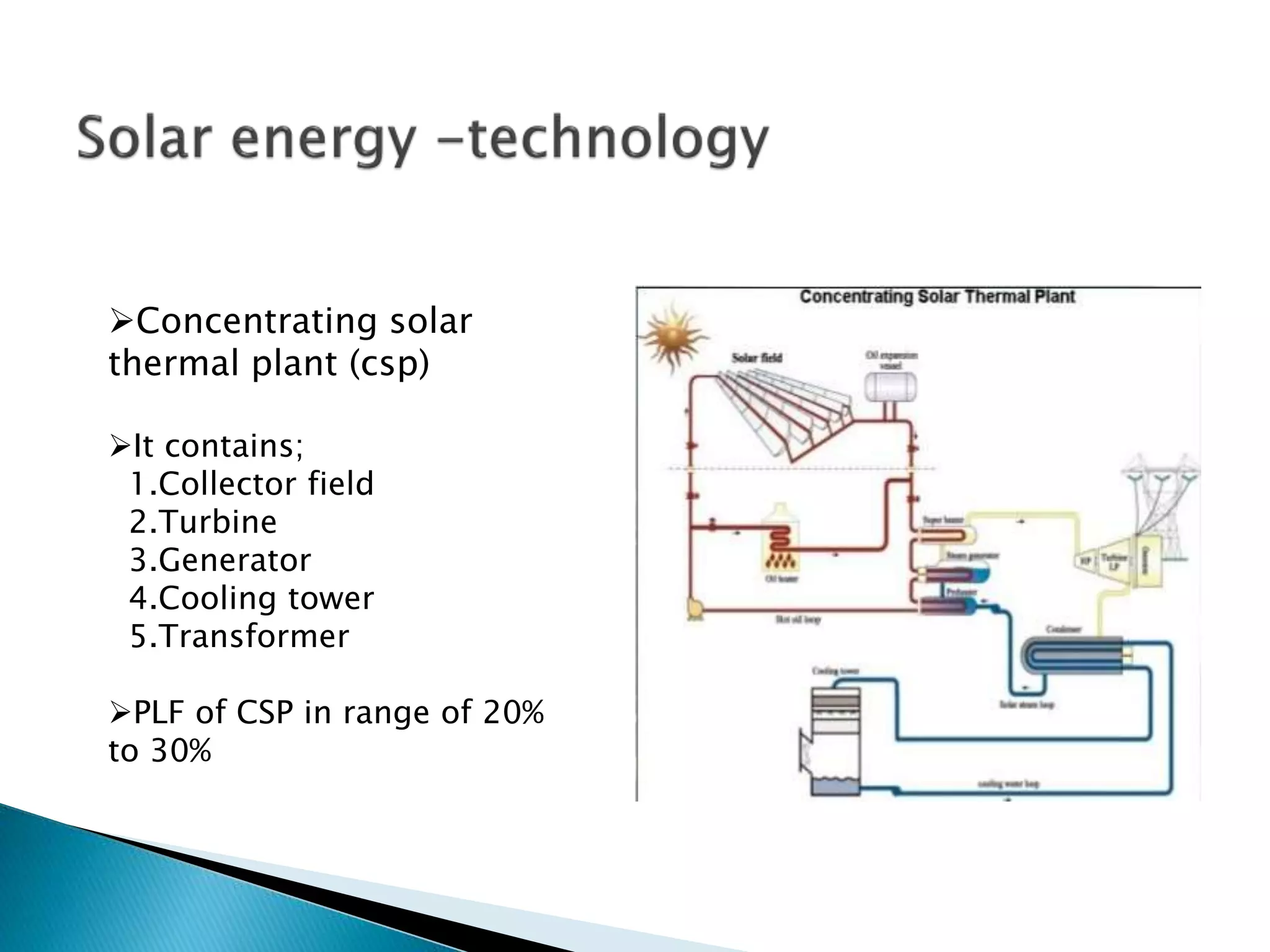
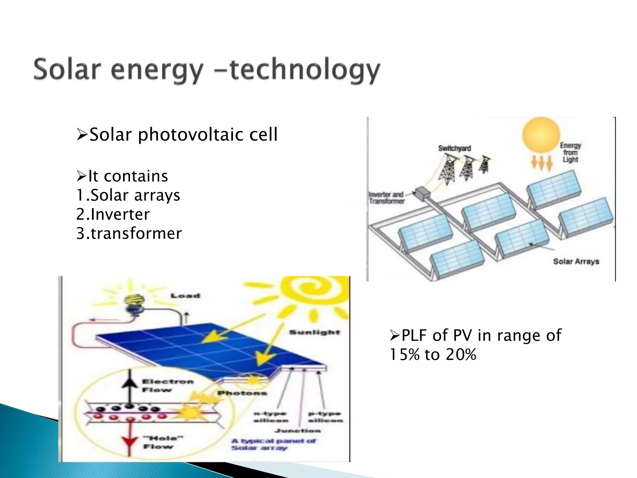
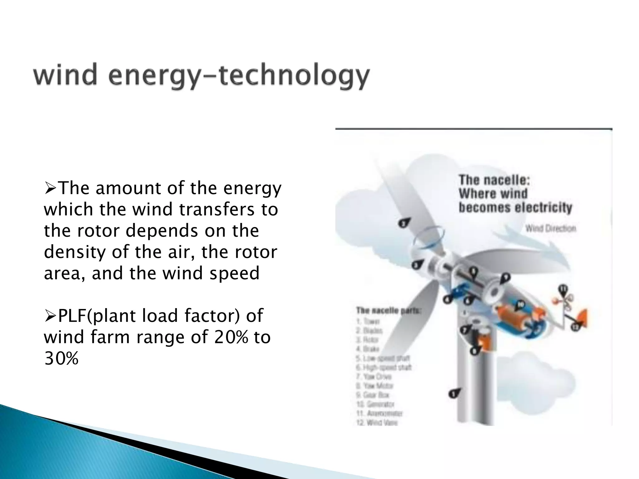
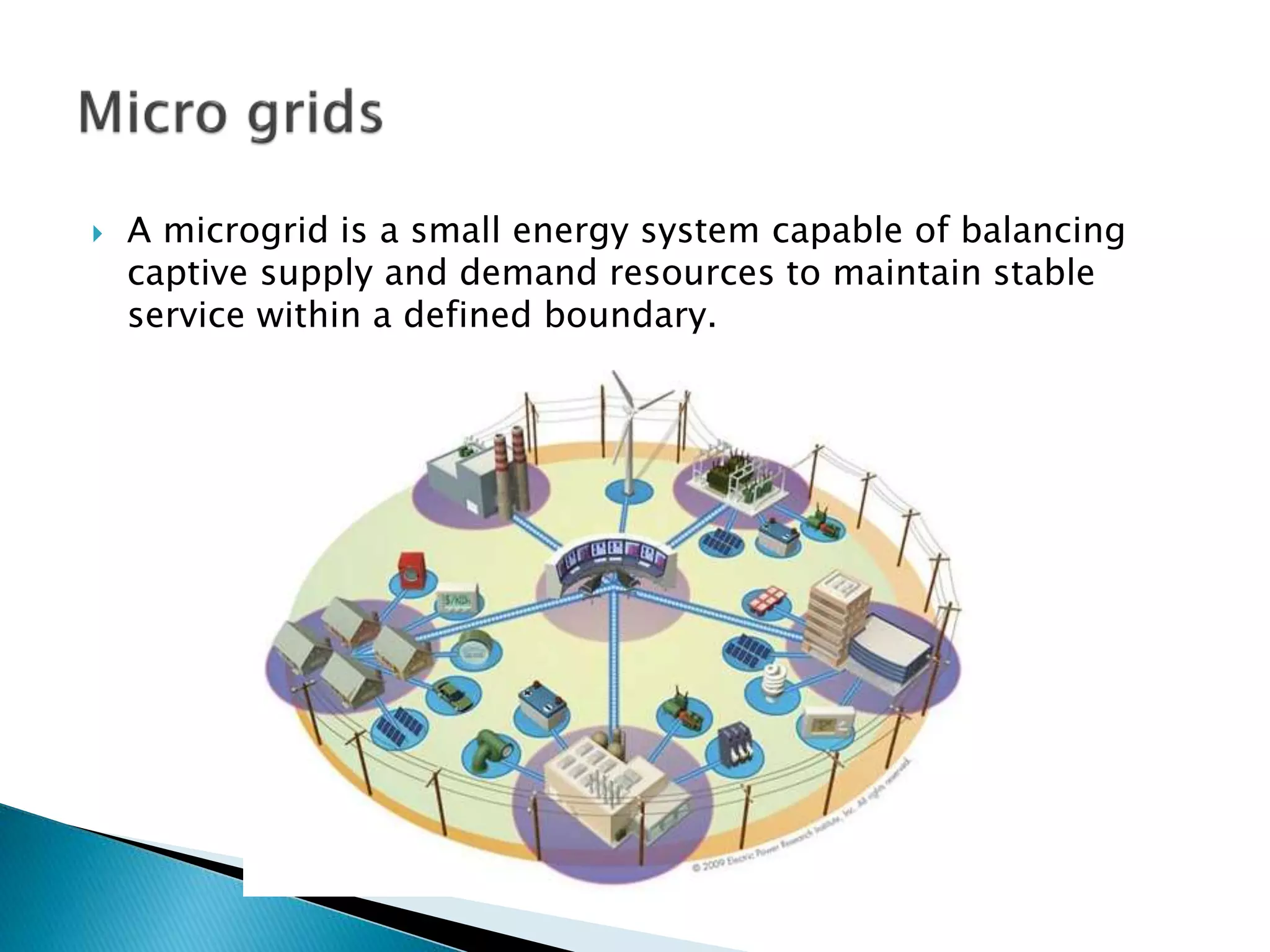
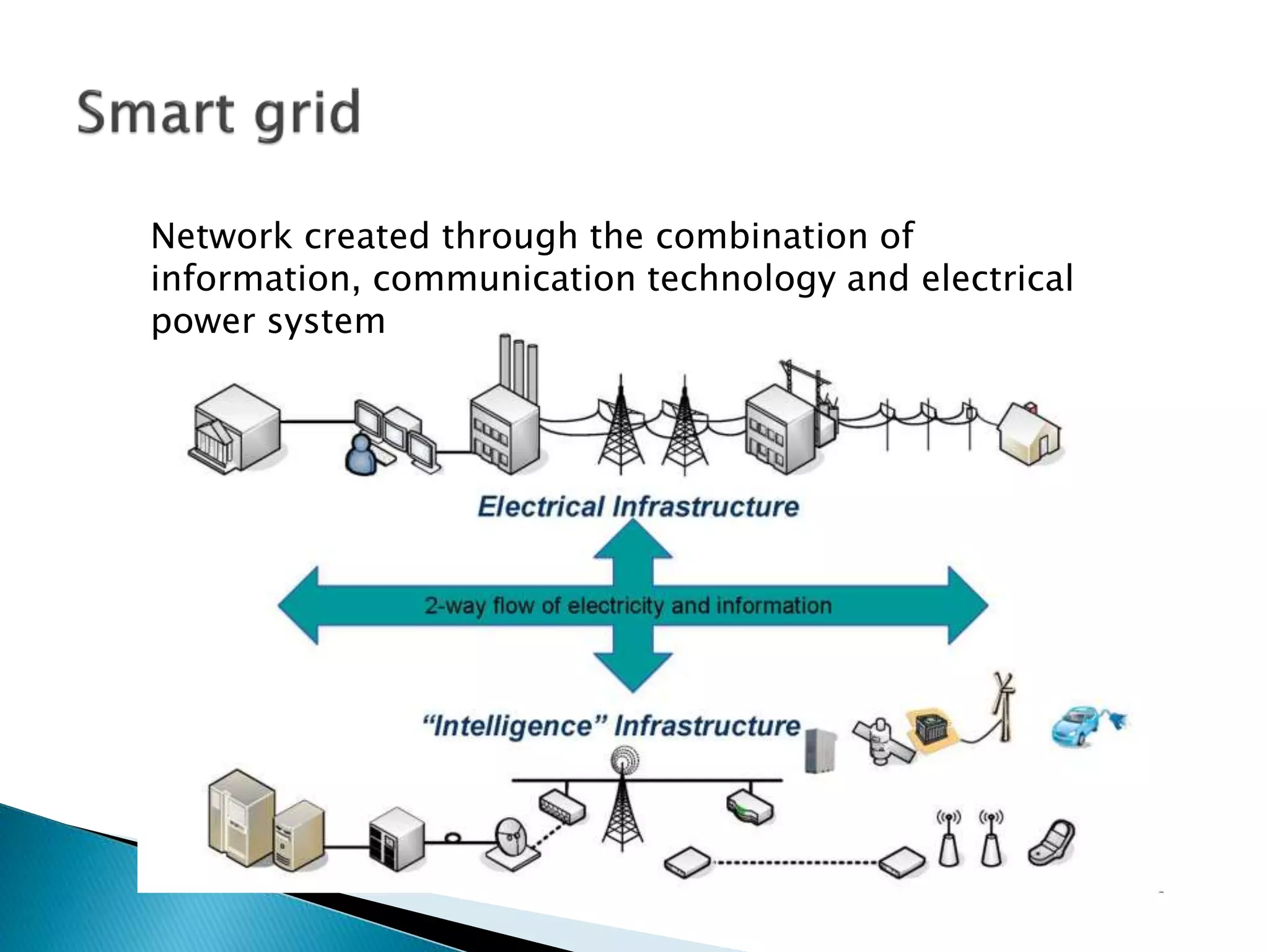
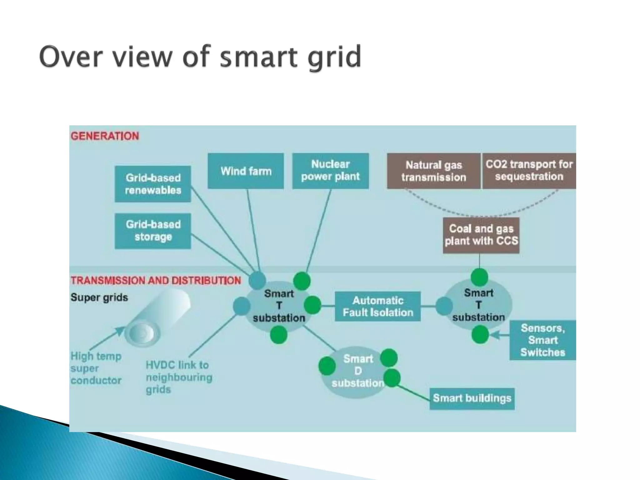
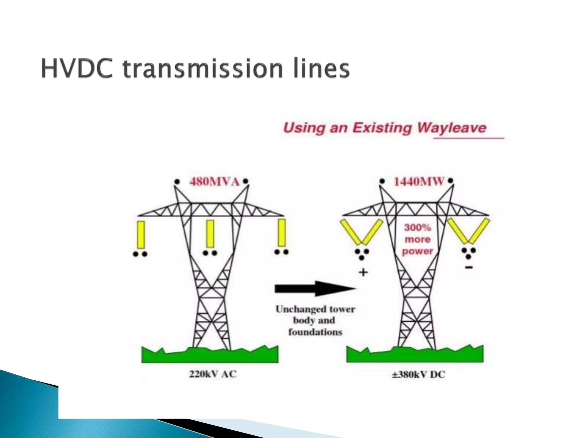
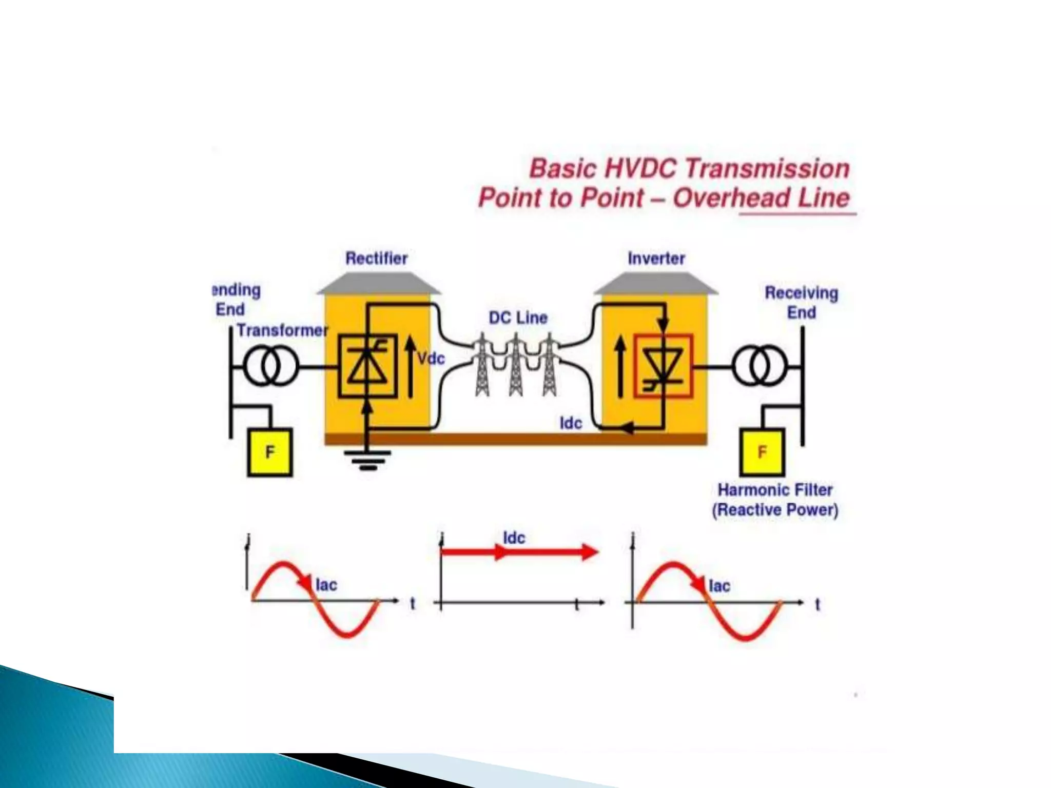
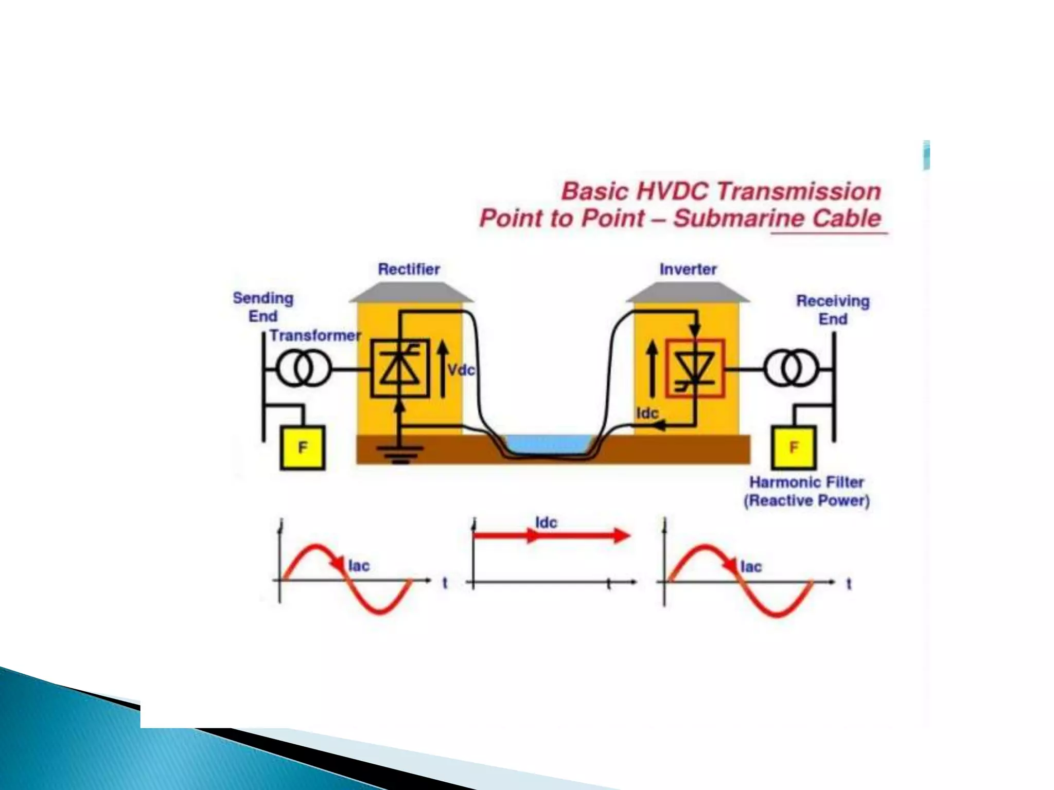
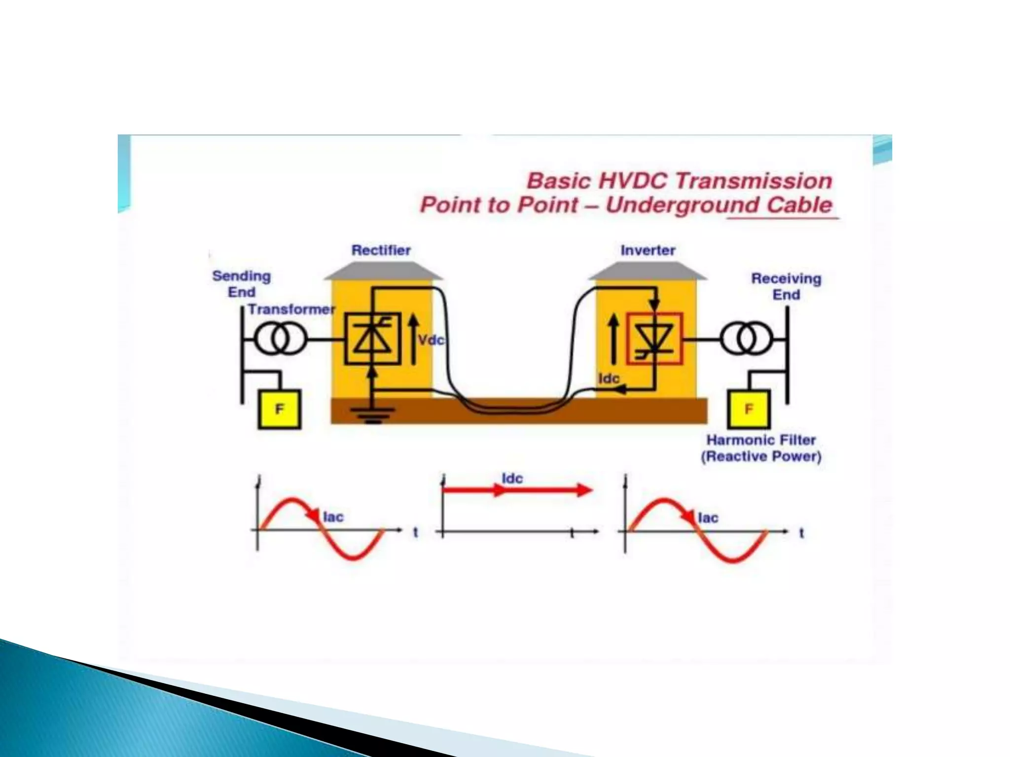
Presentation by:
P. Sravan Kumar
U. Niranjan Mahesh
P. Siva sai Krishna
ANITS college of
engineering ,sangivalasa
,Vishakhapatnam dist
 Introduction
 Renewable resources
 Smart grids and Micro grids
 Power quality-FACTS
 HVDC
 Conclusion
 Renewable sources are solar and wind energy, biomass, bio-
fuel, tidal, geothermal, wave energies.
 Most commonly used are solar and wind energies.
 Solar power is conversion of sunlight into electricity
 The most advance way of conversion of sunlight into
electricity are:
1.concentrating solar thermal plant(CSP)
2.photovoltaic cells(PV)
 Wind power can be converted into electricity by using
turbines
Concentrating solar
thermal plant (csp)
It contains;
1.Collector field
2.Turbine
3.Generator
4.Cooling tower
5.Transformer
PLF of CSP in range of 20%
to 30%
Solar photovoltaic cell
It contains
1.Solar arrays
2.Inverter
3.transformer
PLF of PV in range of
15% to 20%
The amount of the energy
which the wind transfers to
the rotor depends on the
density of the air, the rotor
area, and the wind speed
PLF(plant load factor) of
wind farm range of 20% to
30%
 A microgrid is a small energy system capable of balancing
captive supply and demand resources to maintain stable
service within a defined boundary.
 Combine various distributed energy resources (DER) to form a
whole system that's greater than its parts.
 Most microgrids can be further described by one of four
categories:
1. Off-grid microgrids
2. Campus microgrids
3. Community microgrid
4. Nano microgrids
 Transmission losses get highly reduced
 Provide high quality and reliable energy supply to critical
loads
 Micro grid results in substantial savings and cuts emissions
without major changes to lifestyles.
 Power sources in case of Microgrid ( often referred to as
Micro sources ) are small and are located in close proximity to
load
 In peak load periods it prevents utility grid failure by reducing
the load on the grid.
 Significant environmental benefits made possible by the use
of low or zero emission generators.
Network created through the combination of
information, communication technology and electrical
power system
 Establishes a two-way communication between the utilities
and the consumers
 Anticipation of faults and helps in fault prevention
 Reduces and shifts the peak demand
 Continuous monitoring and feedback from network
 Def: The quality of the voltage rather than power or electrical
current.
 Power is simply the flow of energy and current demanded by
a load is largely uncontrollable.
 Voltage provided should be as close to nominal voltage and
wave form must be pure sine wave free form harmonics and
other disturbances
 They are:
1. Voltage sags
2. Micro-interruptions
3. Long interruptions
4. Voltage spikes
5. Voltage swells
6. Harmonic distortion
 FACTS (Flexible AC Transmission):P.E base systems & other
static equipment that provide control of one or more AC
transmission system parameters to enhance controllability &
increase power transfer capability
 In order to rectify the problems in power quality the FACTS
devices are used.
 Control power so that it flows on the desired routes
 Increase loading capacity of transmission lines.
 Prevent blackouts.
 Improve generation productivity
 Effective use of upgrading/ uprating.
 Series compensation:
In this FACTS are connected in series with power
system hence it works as a controllable voltage source
 In long lines, when a large current flows, this causes a large
voltage drop. To compensate, series capacitors are
connected, decreasing the effect of the inductance
 Shunt compensation:
In shunt compensation, power system is connected
in shunt (parallel) with the FACTS. It works as a
controllable current sources. Shunt compensation is of two
types:
1. Shunt capacitive compensation
2. Shunt inductive compensation
 It is a static synchronous generator as shunt static var
compensator whose capacitive or inductive current can be
controlled independent of the system voltage
 The STATCOM scheme in parallel with AC power grid system
and is controlled by a dynamic controller
 A High-voltage DC electric power transmission system uses
DC for bulk transmission of electric power, in contract with
the more common AC systems
 HVDC allows power transmission between unsynchronized AC
transmission systems
 An HVDC link can be controlled independently of the phase
angle between source and load, it can stabilize a network
against disturbances due to rapid changes in power
 Converters
 Smoothing reactors
 Harmonic filters
 Reactive power supplier
 electrodes
 Practical absence of transmission line length limitations
 Interconnection of asynchronously operated power systems
 No increase of short circuit power at connection point
 Lesser corona loss and ratio interface
 Can be used for submarine and underground transmission
 Low cost of DC lines and cables
 Simple in construction
 Low cost for insulators and towers
 Less line losses
 Transmission line can be built in stages
 If the overhead transmission is long enough, say 1500 Km,
the saving in capital costs and losses with a dc transmission
line may be enough to pay for two converters. This distance is
known as break-even distance.
 This break-even distance is very subject to many factors
including the cost of the line, right-of-way, and often most
important the politics of obtaining permission to build the
line.
 But it is important to recognize that while FACTS can play
an important role in an effective use of ac transmission, it
probably does not have too much influence on the break-
even distance.
 The role of HVDC is to interconnect ac systems where a
reliable ac interconnection would be too expensive
Independent frequency and control
Lower line cost
Power control, voltage control and stability control possible
 The large market potential for FACTS is within AC system on
a value added basis where
The existing steady-state phase angle between bus node is
reasonable
The cost of FACTS solution is lower than the HVDC cost
The required FACTS controller capacity is lesser than the
transmission rating
Advances in power systems

Advances in power systems

  • 1.
    Presentation by: P. SravanKumar U. Niranjan Mahesh P. Siva sai Krishna ANITS college of engineering ,sangivalasa ,Vishakhapatnam dist
  • 2.
     Introduction  Renewableresources  Smart grids and Micro grids  Power quality-FACTS  HVDC  Conclusion
  • 3.
     Renewable sourcesare solar and wind energy, biomass, bio- fuel, tidal, geothermal, wave energies.  Most commonly used are solar and wind energies.  Solar power is conversion of sunlight into electricity  The most advance way of conversion of sunlight into electricity are: 1.concentrating solar thermal plant(CSP) 2.photovoltaic cells(PV)  Wind power can be converted into electricity by using turbines
  • 4.
    Concentrating solar thermal plant(csp) It contains; 1.Collector field 2.Turbine 3.Generator 4.Cooling tower 5.Transformer PLF of CSP in range of 20% to 30%
  • 5.
    Solar photovoltaic cell Itcontains 1.Solar arrays 2.Inverter 3.transformer PLF of PV in range of 15% to 20%
  • 6.
    The amount ofthe energy which the wind transfers to the rotor depends on the density of the air, the rotor area, and the wind speed PLF(plant load factor) of wind farm range of 20% to 30%
  • 7.
     A microgridis a small energy system capable of balancing captive supply and demand resources to maintain stable service within a defined boundary.
  • 8.
     Combine variousdistributed energy resources (DER) to form a whole system that's greater than its parts.  Most microgrids can be further described by one of four categories: 1. Off-grid microgrids 2. Campus microgrids 3. Community microgrid 4. Nano microgrids
  • 9.
     Transmission lossesget highly reduced  Provide high quality and reliable energy supply to critical loads  Micro grid results in substantial savings and cuts emissions without major changes to lifestyles.
  • 10.
     Power sourcesin case of Microgrid ( often referred to as Micro sources ) are small and are located in close proximity to load  In peak load periods it prevents utility grid failure by reducing the load on the grid.  Significant environmental benefits made possible by the use of low or zero emission generators.
  • 11.
    Network created throughthe combination of information, communication technology and electrical power system
  • 12.
     Establishes atwo-way communication between the utilities and the consumers  Anticipation of faults and helps in fault prevention  Reduces and shifts the peak demand  Continuous monitoring and feedback from network
  • 14.
     Def: Thequality of the voltage rather than power or electrical current.  Power is simply the flow of energy and current demanded by a load is largely uncontrollable.  Voltage provided should be as close to nominal voltage and wave form must be pure sine wave free form harmonics and other disturbances
  • 15.
     They are: 1.Voltage sags 2. Micro-interruptions 3. Long interruptions 4. Voltage spikes 5. Voltage swells 6. Harmonic distortion
  • 17.
     FACTS (FlexibleAC Transmission):P.E base systems & other static equipment that provide control of one or more AC transmission system parameters to enhance controllability & increase power transfer capability  In order to rectify the problems in power quality the FACTS devices are used.
  • 18.
     Control powerso that it flows on the desired routes  Increase loading capacity of transmission lines.  Prevent blackouts.  Improve generation productivity  Effective use of upgrading/ uprating.
  • 19.
     Series compensation: Inthis FACTS are connected in series with power system hence it works as a controllable voltage source  In long lines, when a large current flows, this causes a large voltage drop. To compensate, series capacitors are connected, decreasing the effect of the inductance
  • 20.
     Shunt compensation: Inshunt compensation, power system is connected in shunt (parallel) with the FACTS. It works as a controllable current sources. Shunt compensation is of two types: 1. Shunt capacitive compensation 2. Shunt inductive compensation
  • 21.
     It isa static synchronous generator as shunt static var compensator whose capacitive or inductive current can be controlled independent of the system voltage  The STATCOM scheme in parallel with AC power grid system and is controlled by a dynamic controller
  • 22.
     A High-voltageDC electric power transmission system uses DC for bulk transmission of electric power, in contract with the more common AC systems  HVDC allows power transmission between unsynchronized AC transmission systems  An HVDC link can be controlled independently of the phase angle between source and load, it can stabilize a network against disturbances due to rapid changes in power
  • 23.
     Converters  Smoothingreactors  Harmonic filters  Reactive power supplier  electrodes
  • 24.
     Practical absenceof transmission line length limitations  Interconnection of asynchronously operated power systems  No increase of short circuit power at connection point  Lesser corona loss and ratio interface  Can be used for submarine and underground transmission
  • 25.
     Low costof DC lines and cables  Simple in construction  Low cost for insulators and towers  Less line losses  Transmission line can be built in stages
  • 26.
     If theoverhead transmission is long enough, say 1500 Km, the saving in capital costs and losses with a dc transmission line may be enough to pay for two converters. This distance is known as break-even distance.  This break-even distance is very subject to many factors including the cost of the line, right-of-way, and often most important the politics of obtaining permission to build the line.  But it is important to recognize that while FACTS can play an important role in an effective use of ac transmission, it probably does not have too much influence on the break- even distance.
  • 27.
     The roleof HVDC is to interconnect ac systems where a reliable ac interconnection would be too expensive Independent frequency and control Lower line cost Power control, voltage control and stability control possible  The large market potential for FACTS is within AC system on a value added basis where The existing steady-state phase angle between bus node is reasonable The cost of FACTS solution is lower than the HVDC cost The required FACTS controller capacity is lesser than the transmission rating