Downloaded 413 times

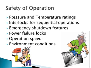
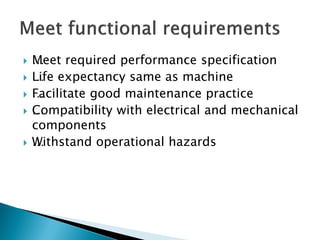
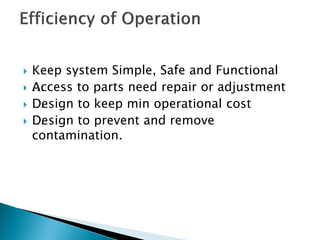
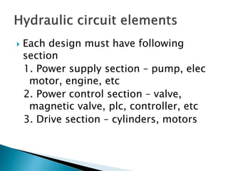
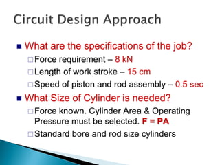
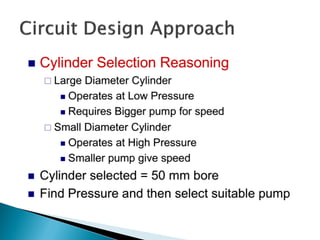
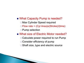
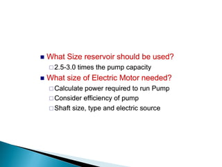
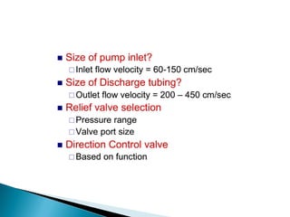
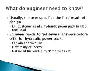
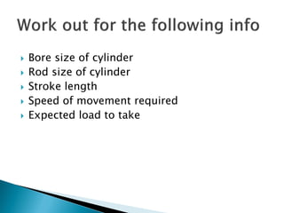
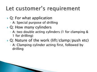
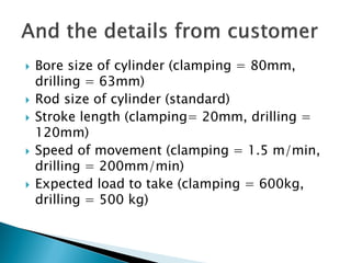
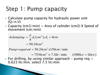
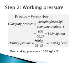
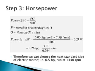
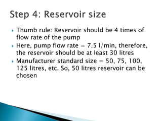
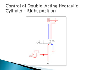
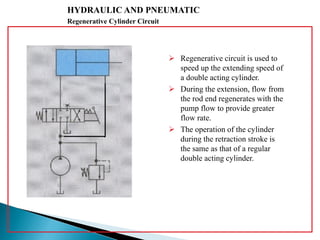
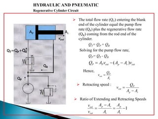
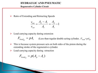

This document discusses the design and analysis of basic hydraulic circuits. It provides guidelines for designing hydraulic circuits including considerations for safety, performance, and efficiency. Key components of hydraulic circuits like pumps, valves, cylinders and reservoirs are described. Methods for calculating pump capacity and sizing other components based on application requirements like bore size, stroke length, load, and speed are covered. Different types of hydraulic circuits for single-acting and double-acting cylinders are illustrated. A regenerative cylinder circuit that increases extending speed is also explained.


![chapterfive [Autosaved].ppt](https://cdn.slidesharecdn.com/ss_thumbnails/chapterfiveautosaved-221227191443-4b610bb9-thumbnail.jpg?width=640&height=640&fit=bounds)


