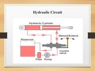
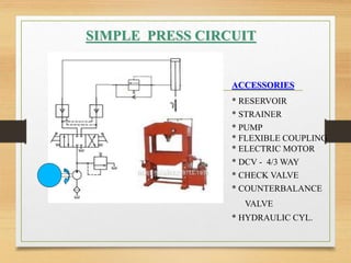
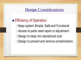
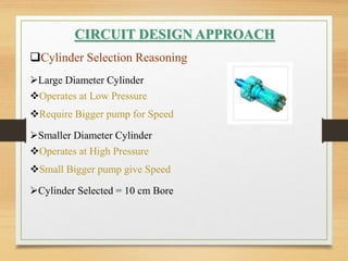
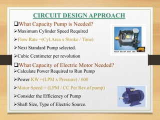
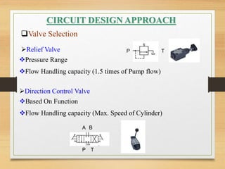
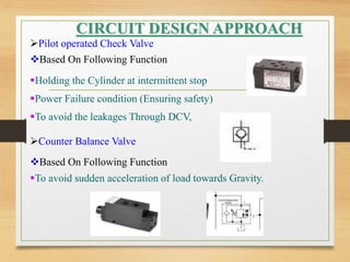
Oil Hydraulics and Pneumatics
(2171912)
Guided By :- Jatin Patel
Presented By :-
Presentation On :-
Basic Design Process of Hydraulic Circuit
GANDHINAGAR
INSTITUTE
OF
TECHNOLOGY
Vaghela Jay (190000000701)
Hydraulic Circuit
Designer Considerations Most
Important Points :-
1. Size of Actuators from Output Objectives.
2. Sequence of Operations type of sequence.
3. Method of control.
4. Operating Pressure.
5. Operating Conditions.
6. Special Requirements.
7. Component Supplies.
SIMPLE PRESS CIRCUIT
* RESERVOIR
* STRAINER
* PUMP
* FLEXIBLE COUPLING
* ELECTRIC MOTOR
* DCV - 4/3 WAY
* CHECK VALVE
* COUNTERBALANCE
VALVE
* HYDRAULIC CYL.
ACCESSORIES
Design Considerations
CIRCUIT DESIGN APPROACH
What are the specification of the job?
Load to be Lifted – 1000 Kg.
Load Travel Distance (Stroke Length)– 50 cm
Time Required to Reach Distance – 10 cm/sec.
What Size of Cylinder Needed?
Which Side Load to be Lifted (Piston or Rod side)
Select the working Pressure (50 to 80 bar apprx .)
Calculate the Area of cylinder A= F / P
Select Standard Bore and Rod size
CIRCUIT DESIGN APPROACH
Cylinder Selection Reasoning
Large Diameter Cylinder
Operates at Low Pressure
Require Bigger pump for Speed
Smaller Diameter Cylinder
Operates at High Pressure
Small Bigger pump give Speed
Cylinder Selected = 10 cm Bore
CIRCUIT DESIGN APPROACH
What Capacity Pump is Needed?
Maximum Cylinder Speed Required
Flow Rate =(Cyl.Area x Stroke / Time)
Next Standard Pump selected.
Cubic Centimeter per revolution
What Capacity of Electric Motor Needed?
Calculate Power Required to Run Pump
Power KW =(LPM x Pressure) / 600
Motor Speed = (LPM / CC Per Rev.of pump)
Consider the Efficiency of Pump
Shaft Size, Type of Electric Source.
CIRCUIT DESIGN APPROACH
What Size of reservoir Should be used?
Basically 4 to 5 times of Pump Capacity. (LxBxH)
Deciding the Length and width Based on
Availability Space
Allowing free Heat Dissipation
Mounting Accessories (Example -Manifold, Filter, Field
piping etc.)
Filler Breather
Suction Strainer,
Return line filter
These are all Selected 2 to 3 times of Pump Capacity
CIRCUIT DESIGN APPROACH
Valve Selection
Relief Valve
Pressure Range
Flow Handling capacity (1.5 times of Pump flow)
Direction Control Valve
Based On Function
Flow Handling capacity (Max. Speed of Cylinder)
P T
A B
P T
Pilot operated Check Valve
Based On Following Function
CIRCUIT DESIGN APPROACH
Holding the Cylinder at intermittent stop
Power Failure condition (Ensuring safety)
To avoid the leakages Through DCV,
Counter Balance Valve
Based On Following Function
To avoid sudden acceleration of load towards Gravity.
Thank You

Jay Vaghela (OHP)

  • 1.
    Oil Hydraulics andPneumatics (2171912) Guided By :- Jatin Patel Presented By :- Presentation On :- Basic Design Process of Hydraulic Circuit GANDHINAGAR INSTITUTE OF TECHNOLOGY Vaghela Jay (190000000701)
  • 2.
  • 3.
    Designer Considerations Most ImportantPoints :- 1. Size of Actuators from Output Objectives. 2. Sequence of Operations type of sequence. 3. Method of control. 4. Operating Pressure. 5. Operating Conditions. 6. Special Requirements. 7. Component Supplies.
  • 4.
    SIMPLE PRESS CIRCUIT *RESERVOIR * STRAINER * PUMP * FLEXIBLE COUPLING * ELECTRIC MOTOR * DCV - 4/3 WAY * CHECK VALVE * COUNTERBALANCE VALVE * HYDRAULIC CYL. ACCESSORIES
  • 5.
  • 6.
  • 7.
    CIRCUIT DESIGN APPROACH Whatare the specification of the job? Load to be Lifted – 1000 Kg. Load Travel Distance (Stroke Length)– 50 cm Time Required to Reach Distance – 10 cm/sec. What Size of Cylinder Needed? Which Side Load to be Lifted (Piston or Rod side) Select the working Pressure (50 to 80 bar apprx .) Calculate the Area of cylinder A= F / P Select Standard Bore and Rod size
  • 8.
    CIRCUIT DESIGN APPROACH CylinderSelection Reasoning Large Diameter Cylinder Operates at Low Pressure Require Bigger pump for Speed Smaller Diameter Cylinder Operates at High Pressure Small Bigger pump give Speed Cylinder Selected = 10 cm Bore
  • 9.
    CIRCUIT DESIGN APPROACH WhatCapacity Pump is Needed? Maximum Cylinder Speed Required Flow Rate =(Cyl.Area x Stroke / Time) Next Standard Pump selected. Cubic Centimeter per revolution What Capacity of Electric Motor Needed? Calculate Power Required to Run Pump Power KW =(LPM x Pressure) / 600 Motor Speed = (LPM / CC Per Rev.of pump) Consider the Efficiency of Pump Shaft Size, Type of Electric Source.
  • 10.
    CIRCUIT DESIGN APPROACH WhatSize of reservoir Should be used? Basically 4 to 5 times of Pump Capacity. (LxBxH) Deciding the Length and width Based on Availability Space Allowing free Heat Dissipation Mounting Accessories (Example -Manifold, Filter, Field piping etc.) Filler Breather Suction Strainer, Return line filter These are all Selected 2 to 3 times of Pump Capacity
  • 11.
    CIRCUIT DESIGN APPROACH ValveSelection Relief Valve Pressure Range Flow Handling capacity (1.5 times of Pump flow) Direction Control Valve Based On Function Flow Handling capacity (Max. Speed of Cylinder) P T A B P T
  • 12.
    Pilot operated CheckValve Based On Following Function CIRCUIT DESIGN APPROACH Holding the Cylinder at intermittent stop Power Failure condition (Ensuring safety) To avoid the leakages Through DCV, Counter Balance Valve Based On Following Function To avoid sudden acceleration of load towards Gravity.
  • 13.