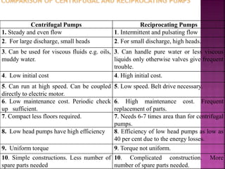
1. The document presents information on centrifugal and reciprocating pumps, including their basic workings, components, uses, and efficiencies.
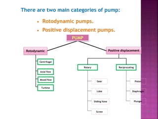
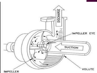
2. Centrifugal pumps use centrifugal force to accelerate and move fluid outwards from the center to increase pressure, while reciprocating pumps use pistons or plungers that move back and forth to displace fluid.
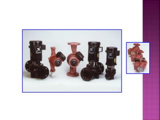
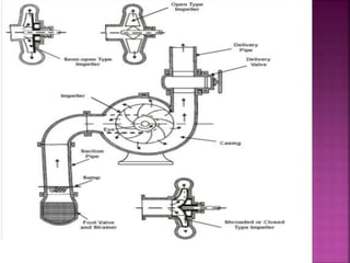
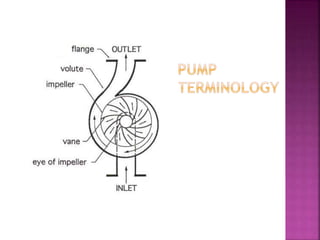
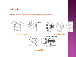
3. Key components of centrifugal pumps include casings, impellers, while reciprocating pumps have cylinders, pistons, valves. Both are used widely for irrigation, industry, buildings and other purposes.