Download as PDF, PPTX
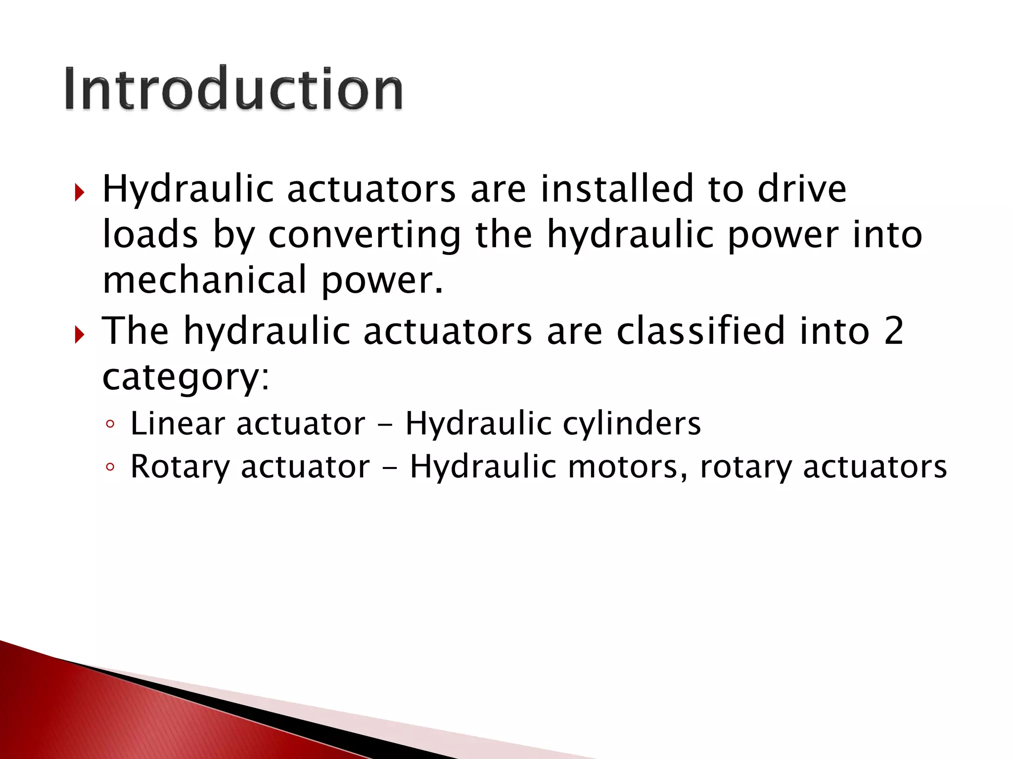
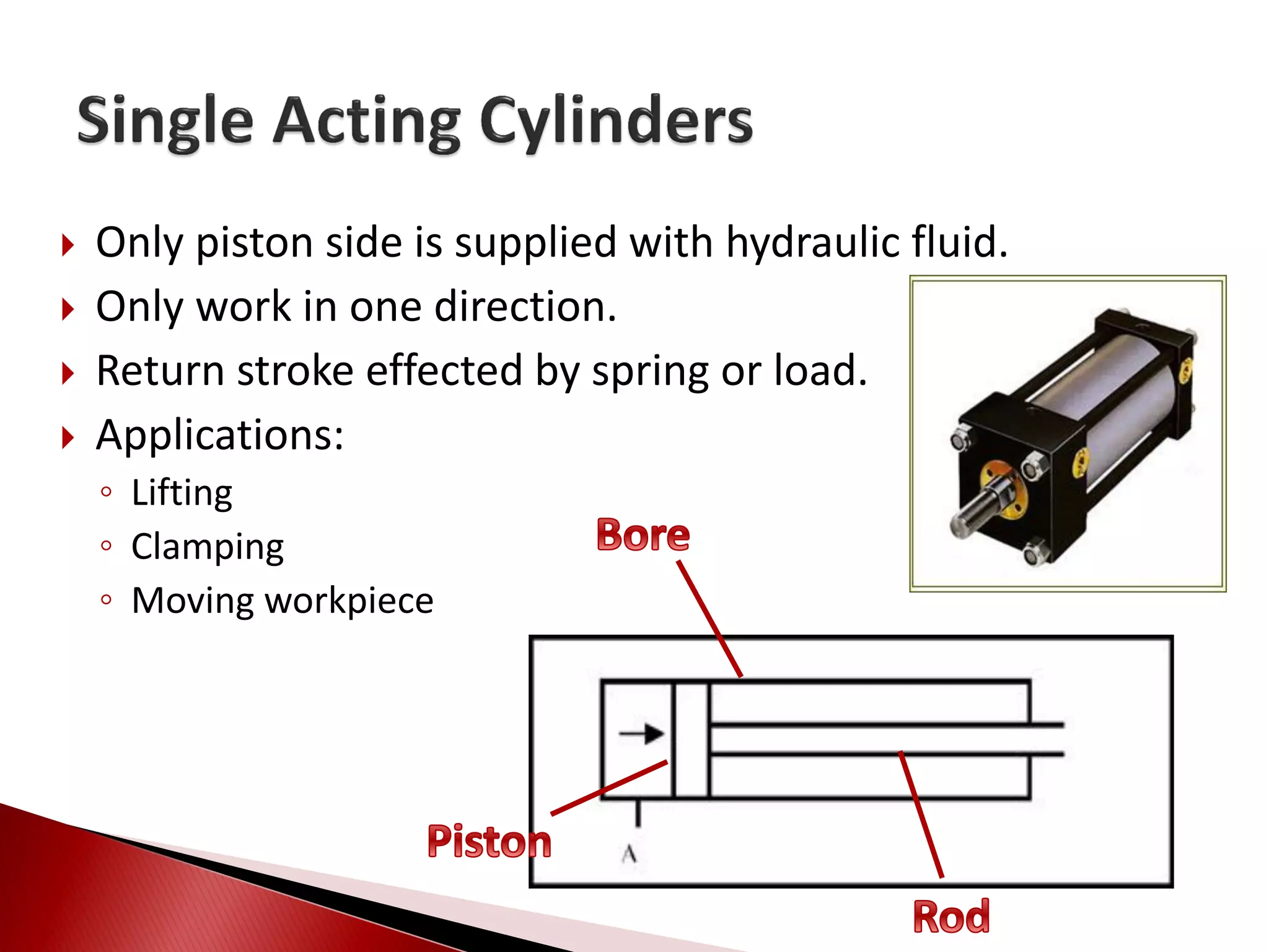
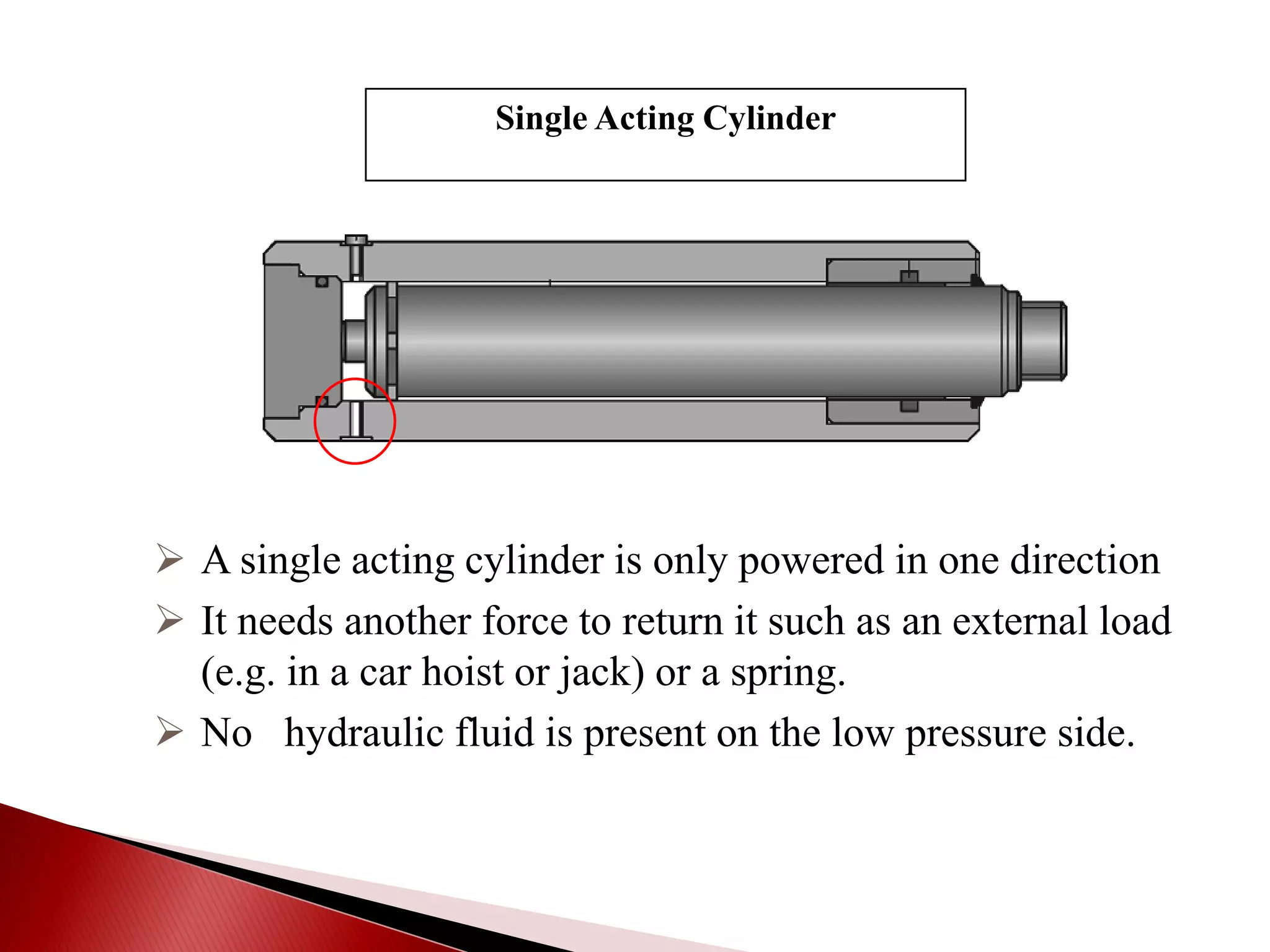
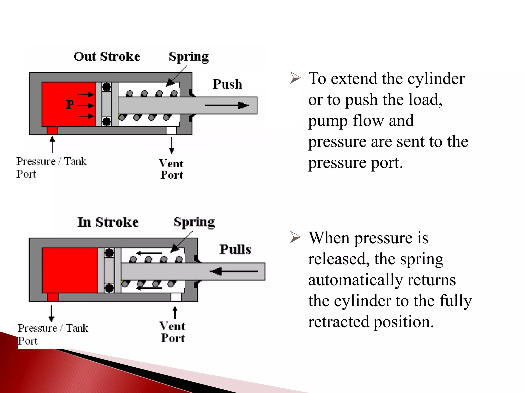
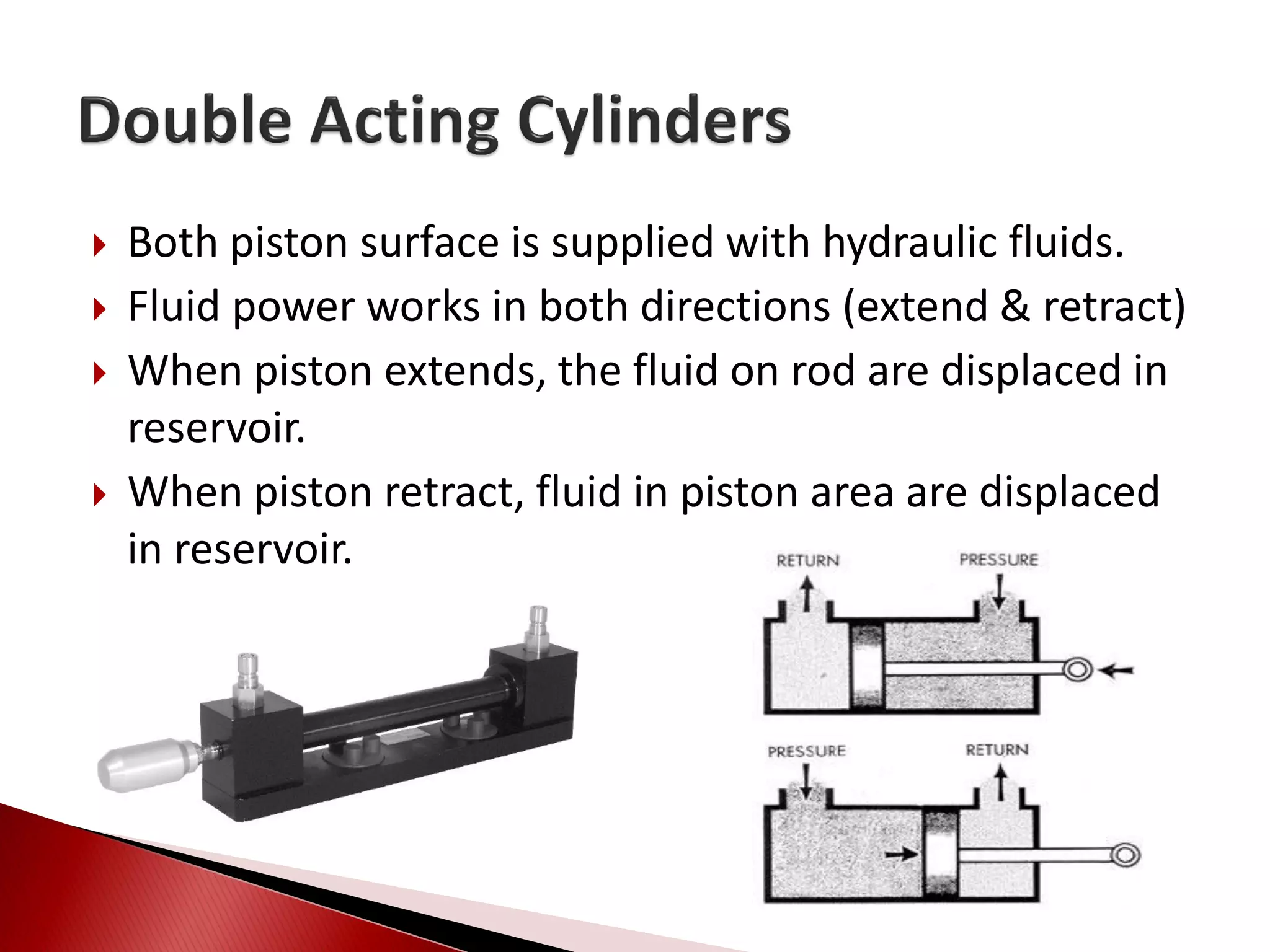
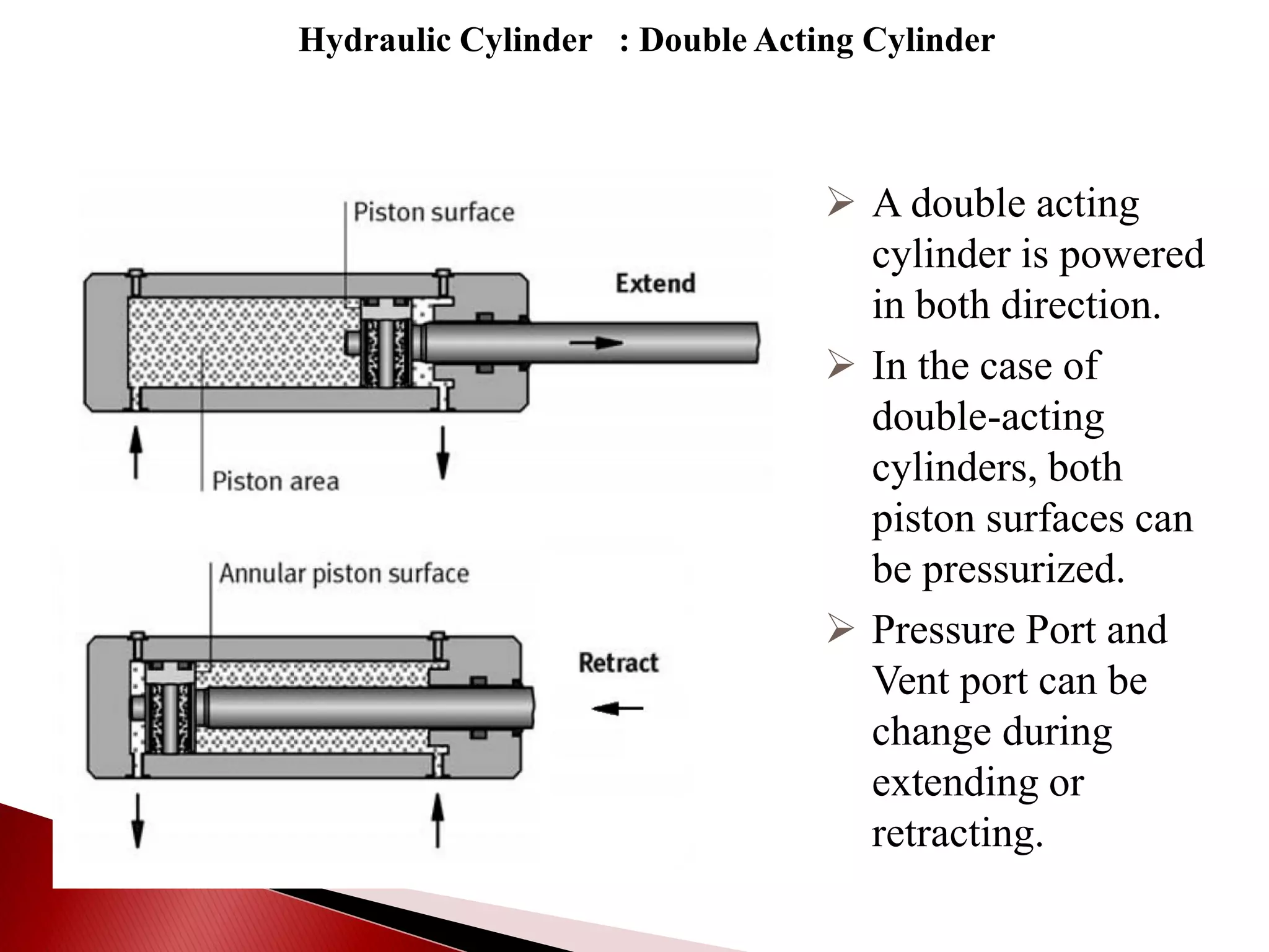
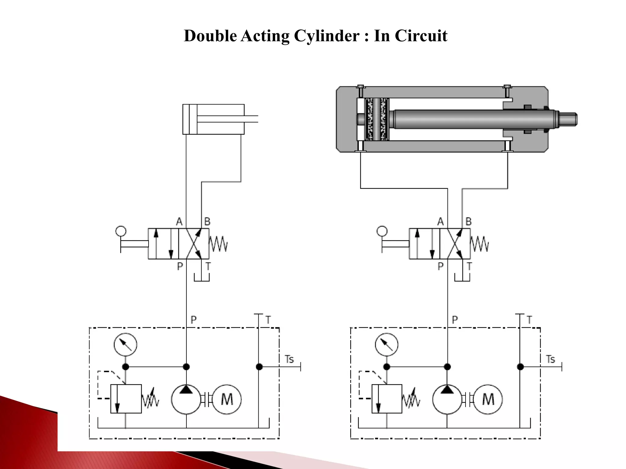
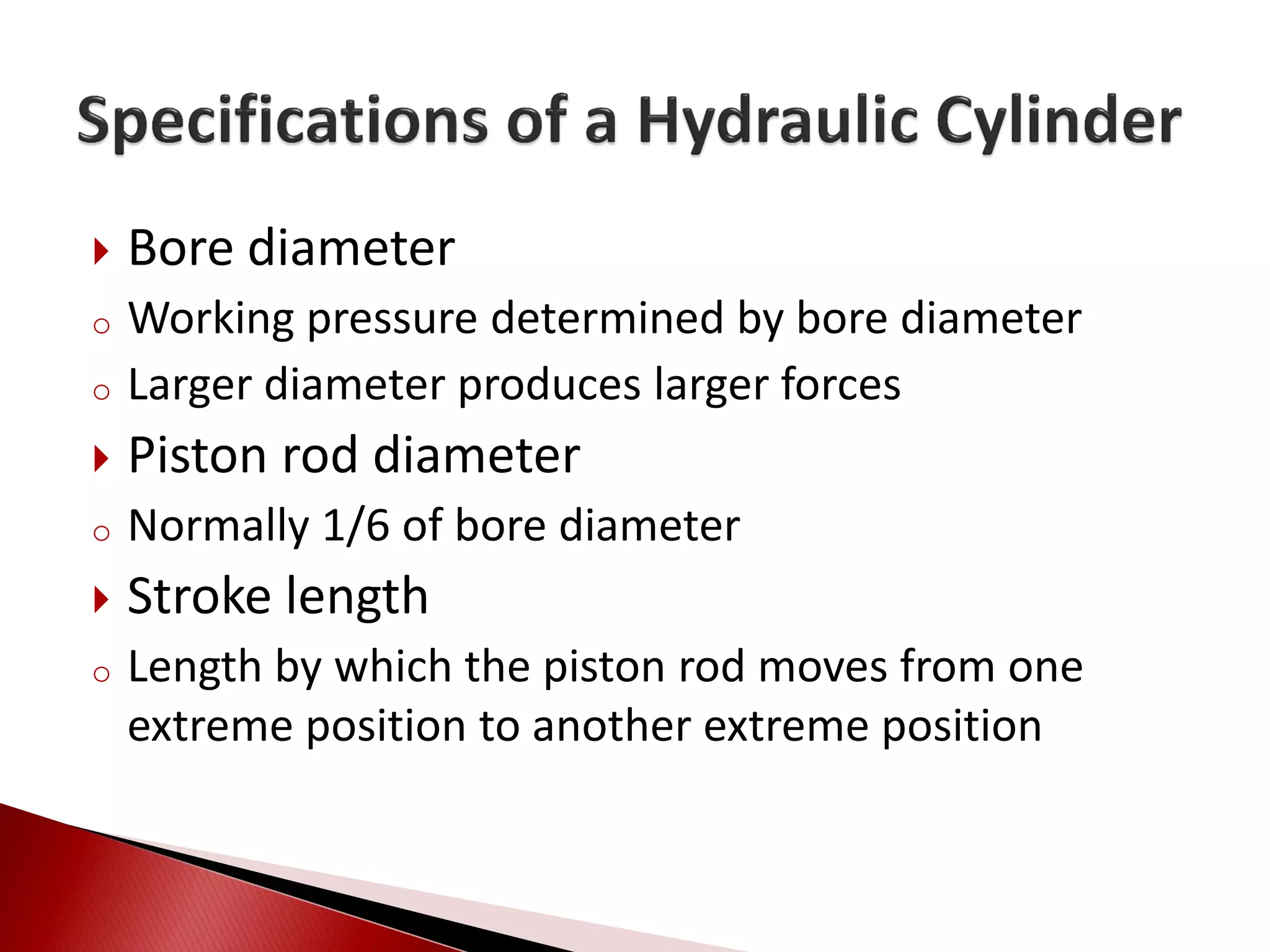
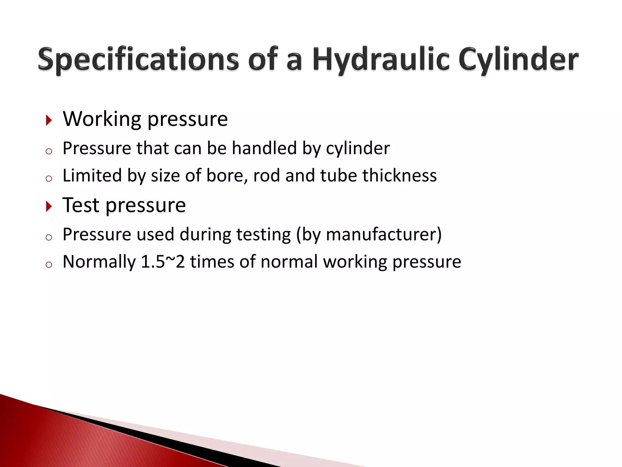
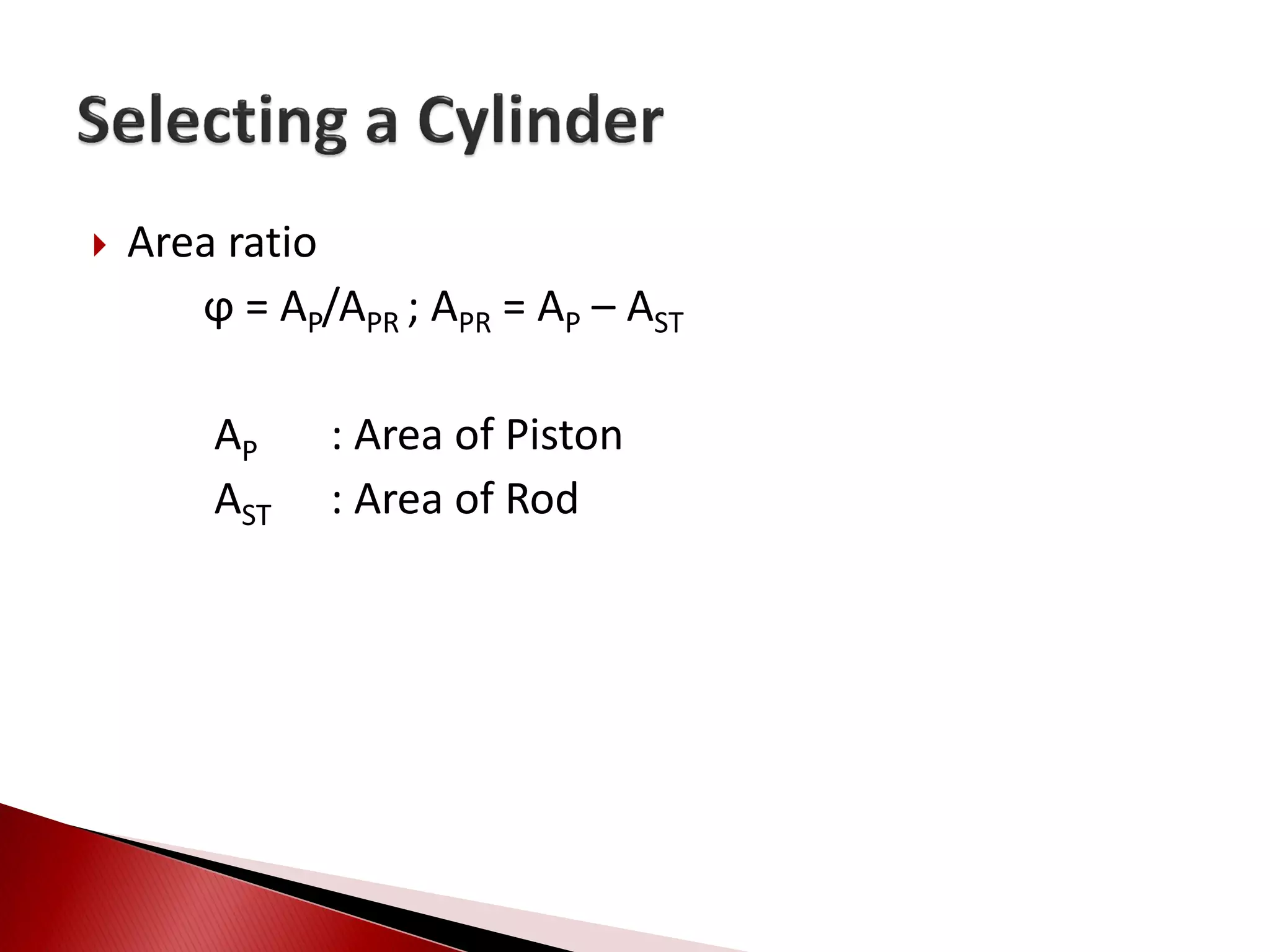
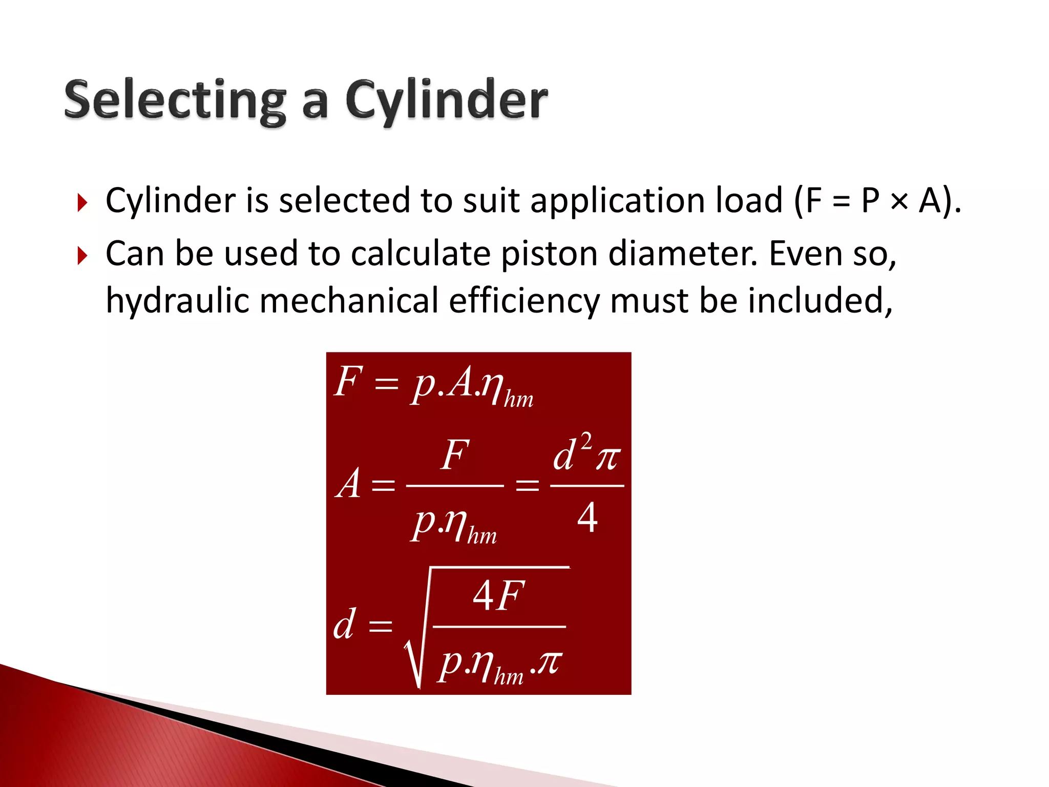
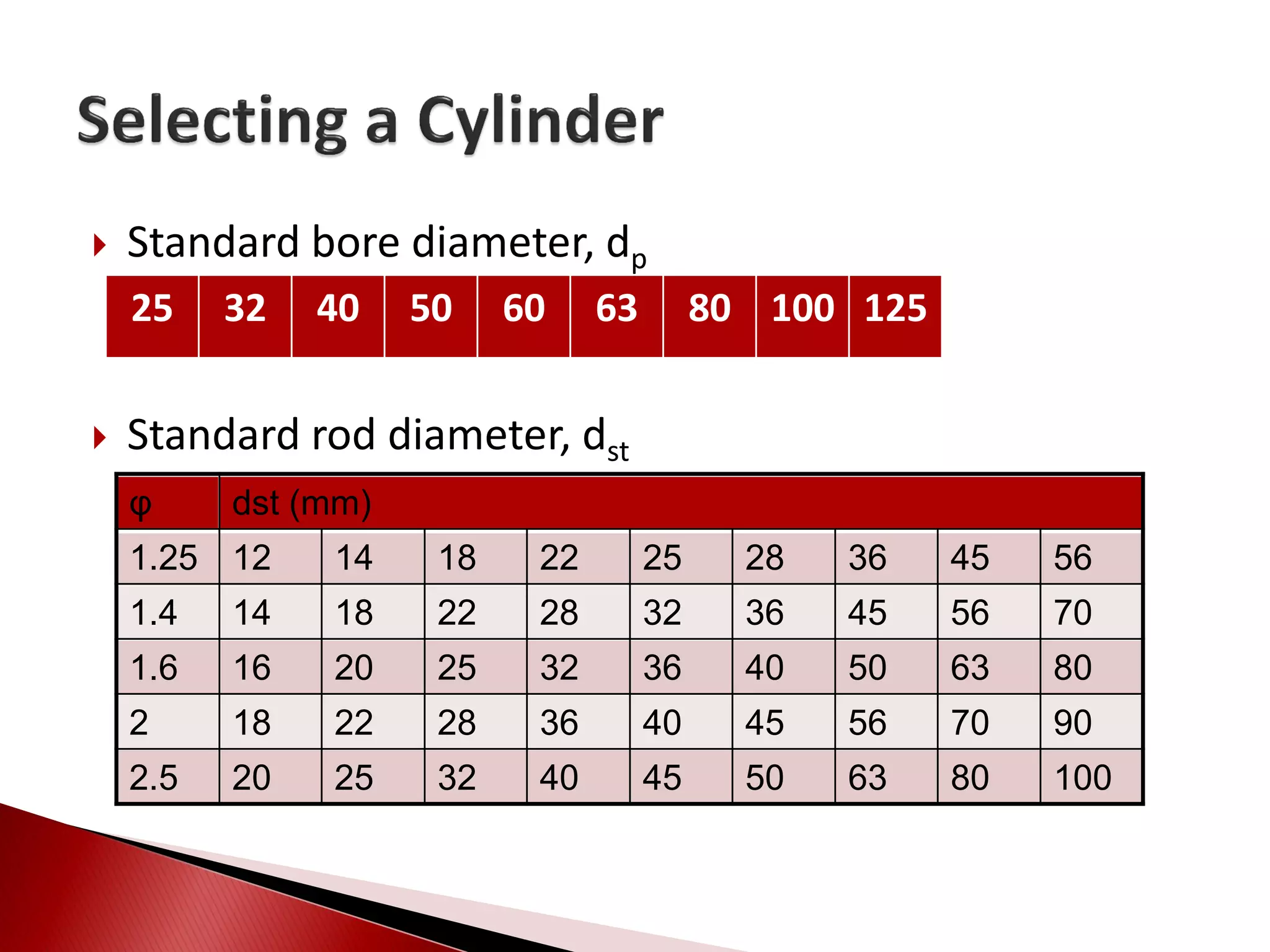
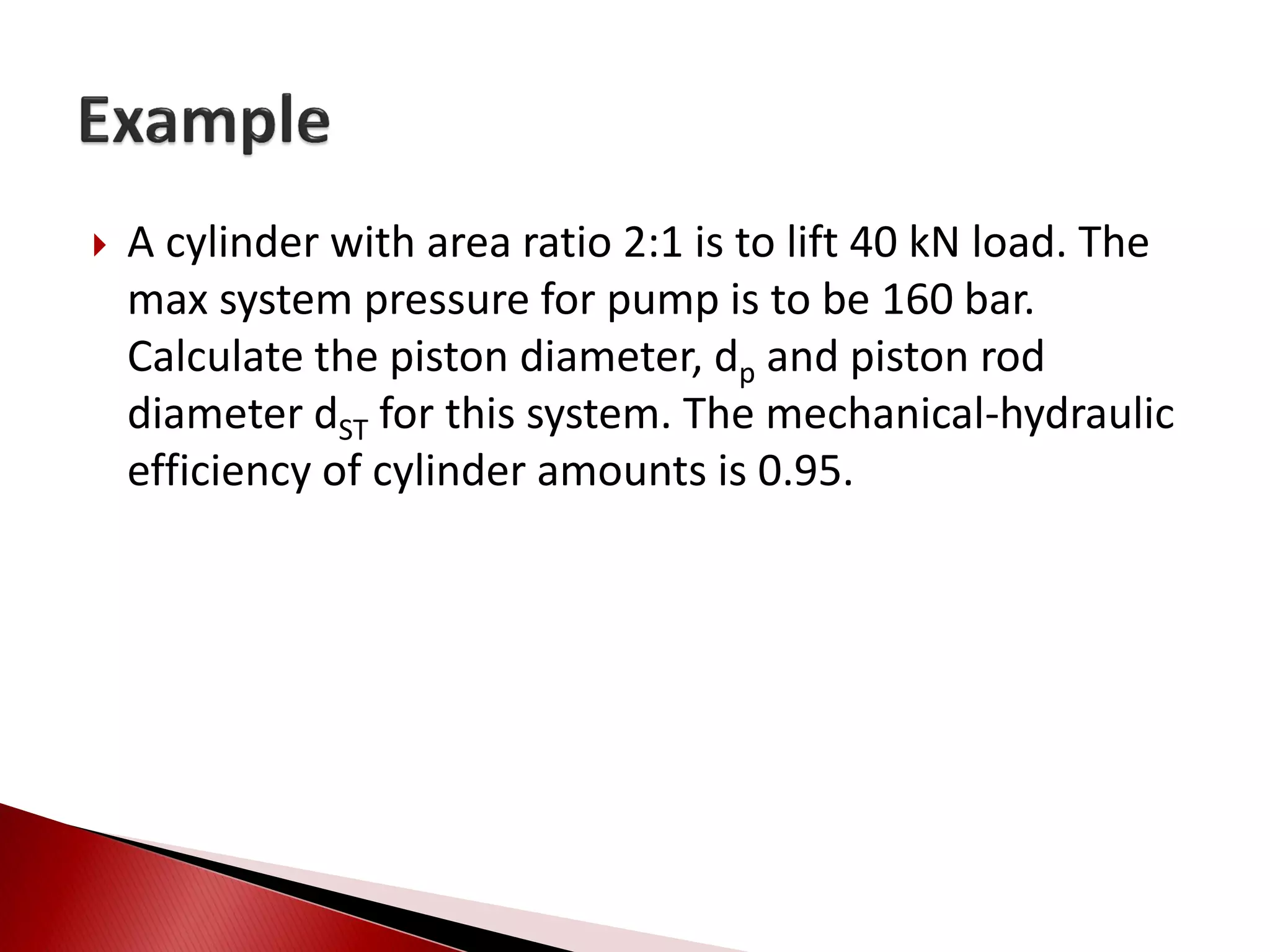

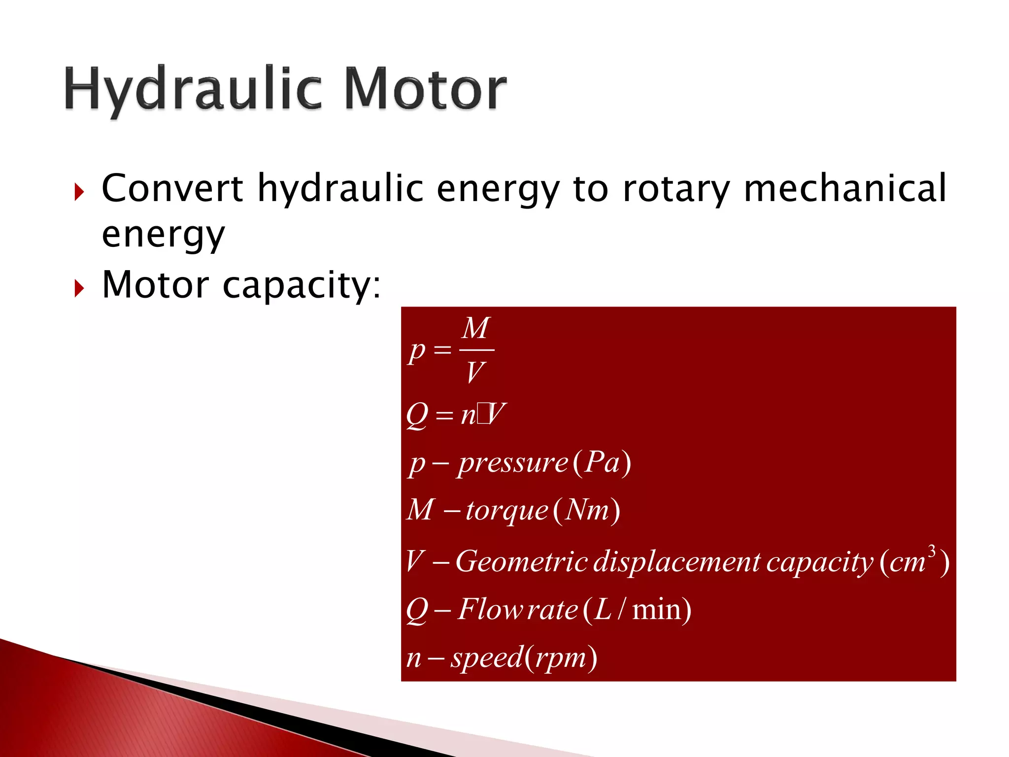
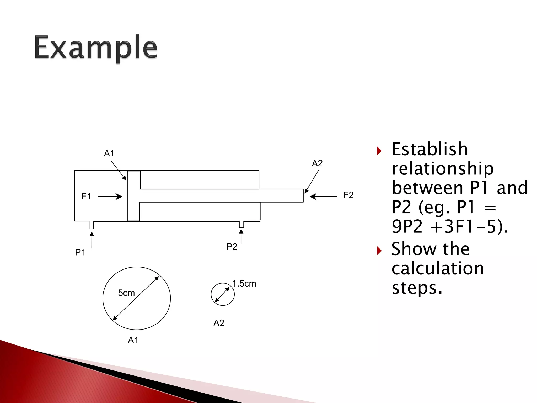
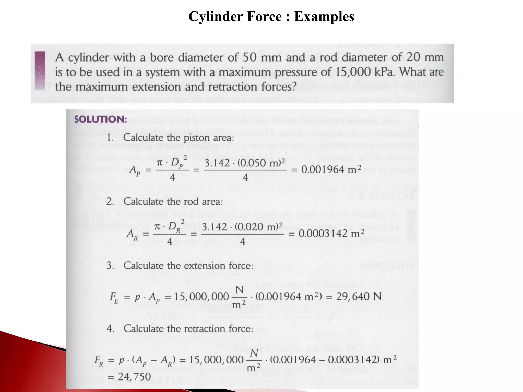
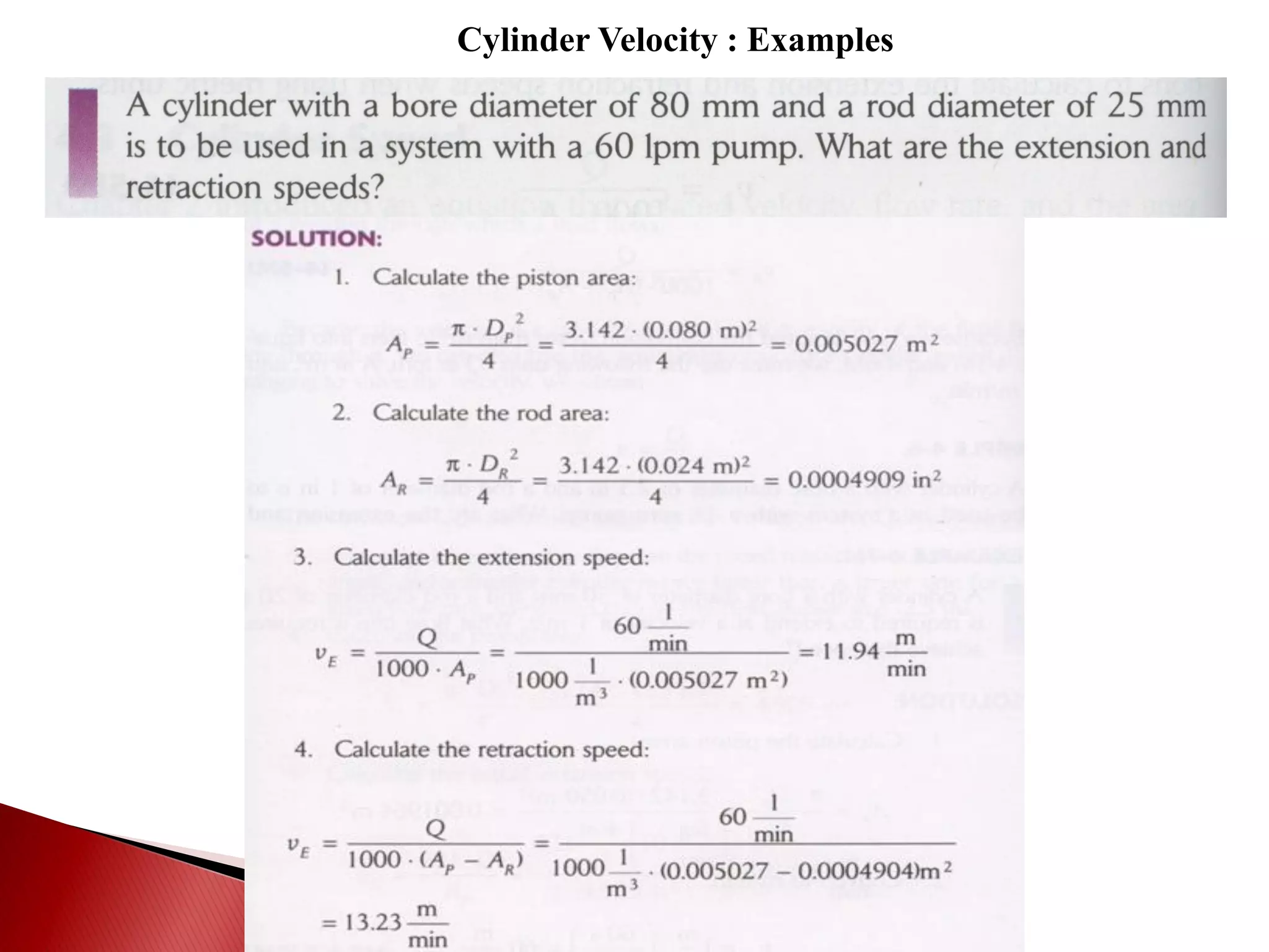
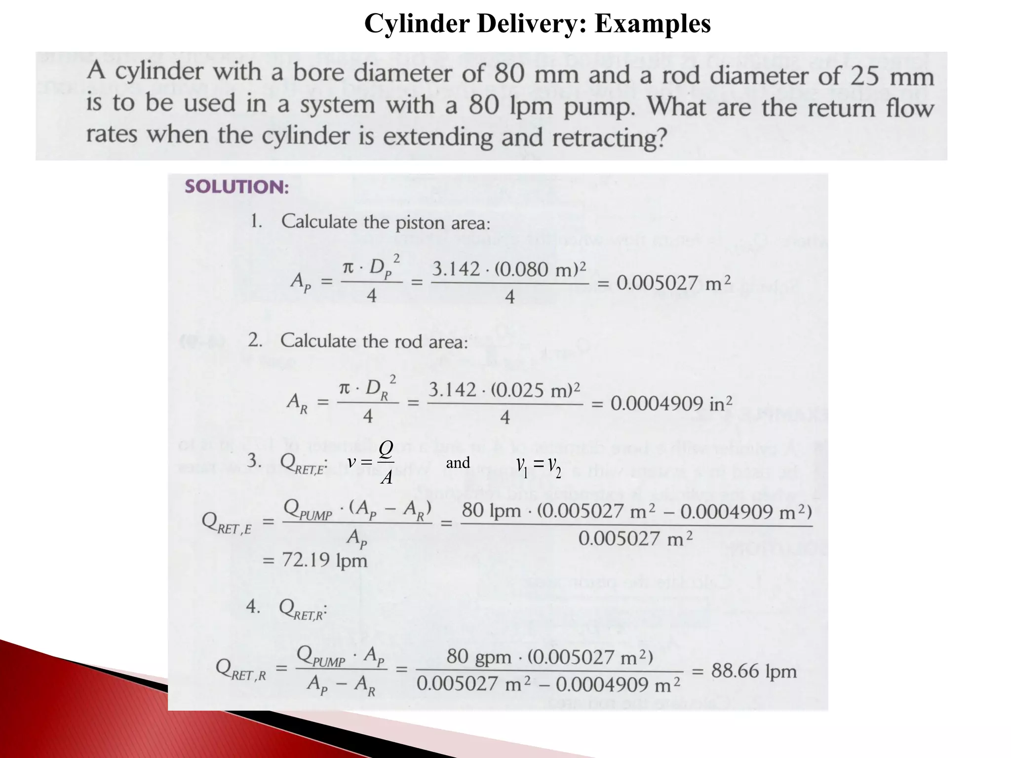
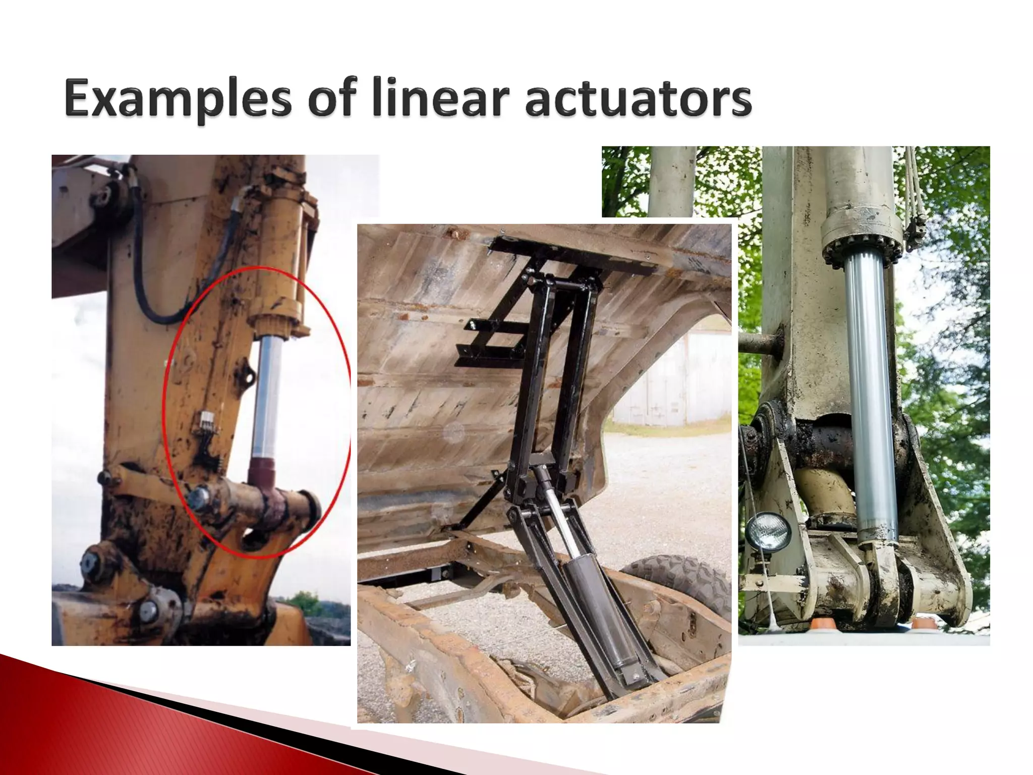

Hydraulic actuators convert hydraulic energy to mechanical motion or force. There are two main types: linear actuators like hydraulic cylinders, and rotary actuators like hydraulic motors. Hydraulic cylinders are further classified as single acting or double acting. Single acting cylinders use pressure on one side of the piston and a spring or external force for return, while double acting cylinders use pressure on both sides to push and pull the piston. Key parameters that determine cylinder selection and sizing include bore diameter, rod diameter, stroke length, working pressure, area ratio, and mechanical efficiency.


![chapterfive [Autosaved].ppt](https://cdn.slidesharecdn.com/ss_thumbnails/chapterfiveautosaved-221227191443-4b610bb9-thumbnail.jpg?width=640&height=640&fit=bounds)


