Downloaded 337 times
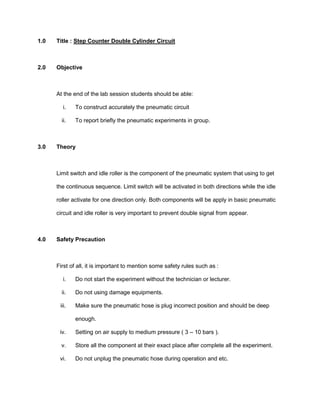


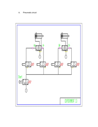


1) The document discusses a pneumatic circuit experiment involving a step counter double cylinder circuit. The objectives are for students to accurately construct the pneumatic circuit and briefly report on their experimental results in a group. 2) It describes the functions of limit switches and idle rollers in pneumatic circuits to achieve continuous sequencing. Safety precautions for the experiment are also provided. 3) The procedure involves identifying components, constructing the circuit diagram, developing the actual circuit, checking connections, and testing the circuit.