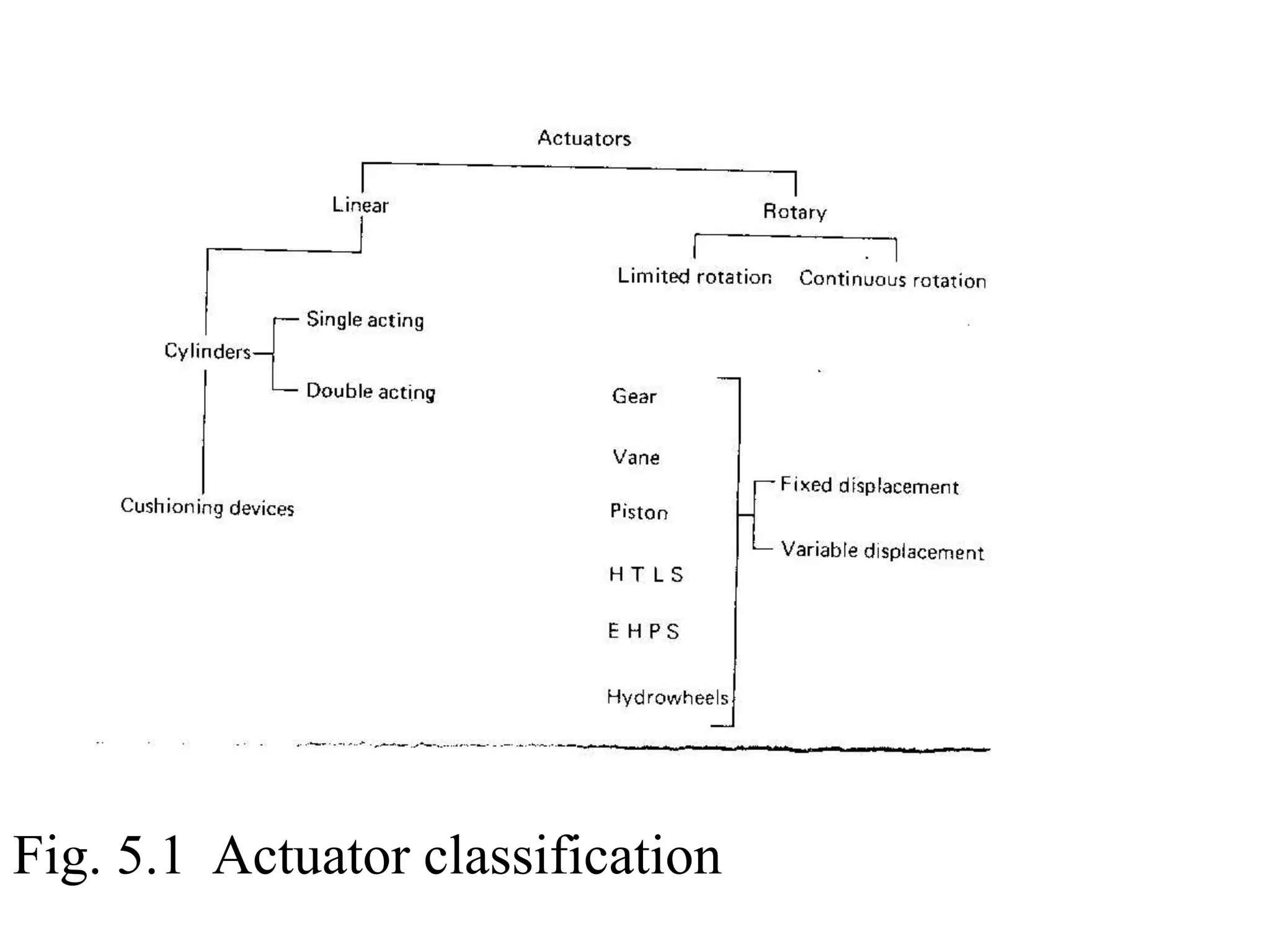
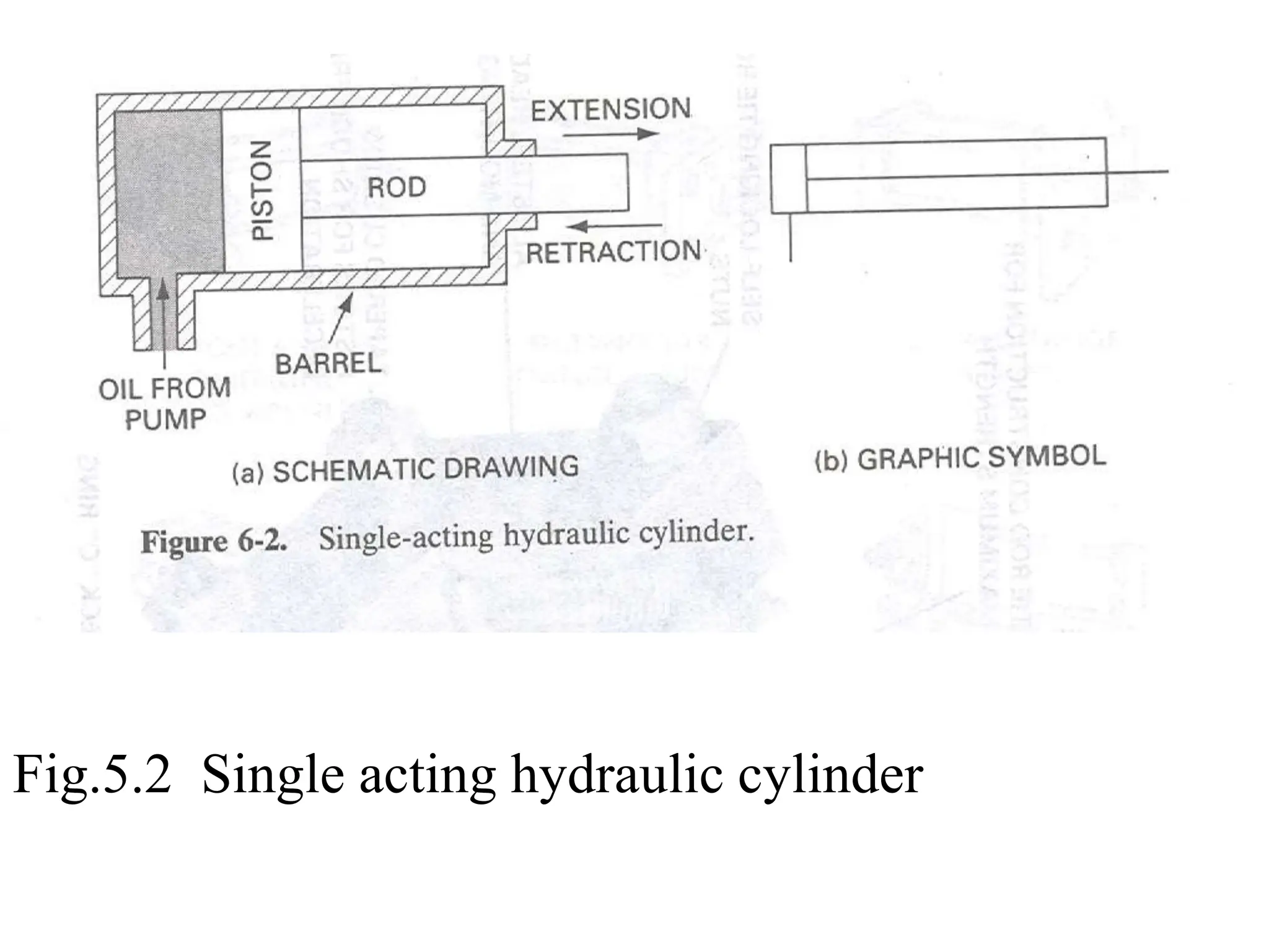
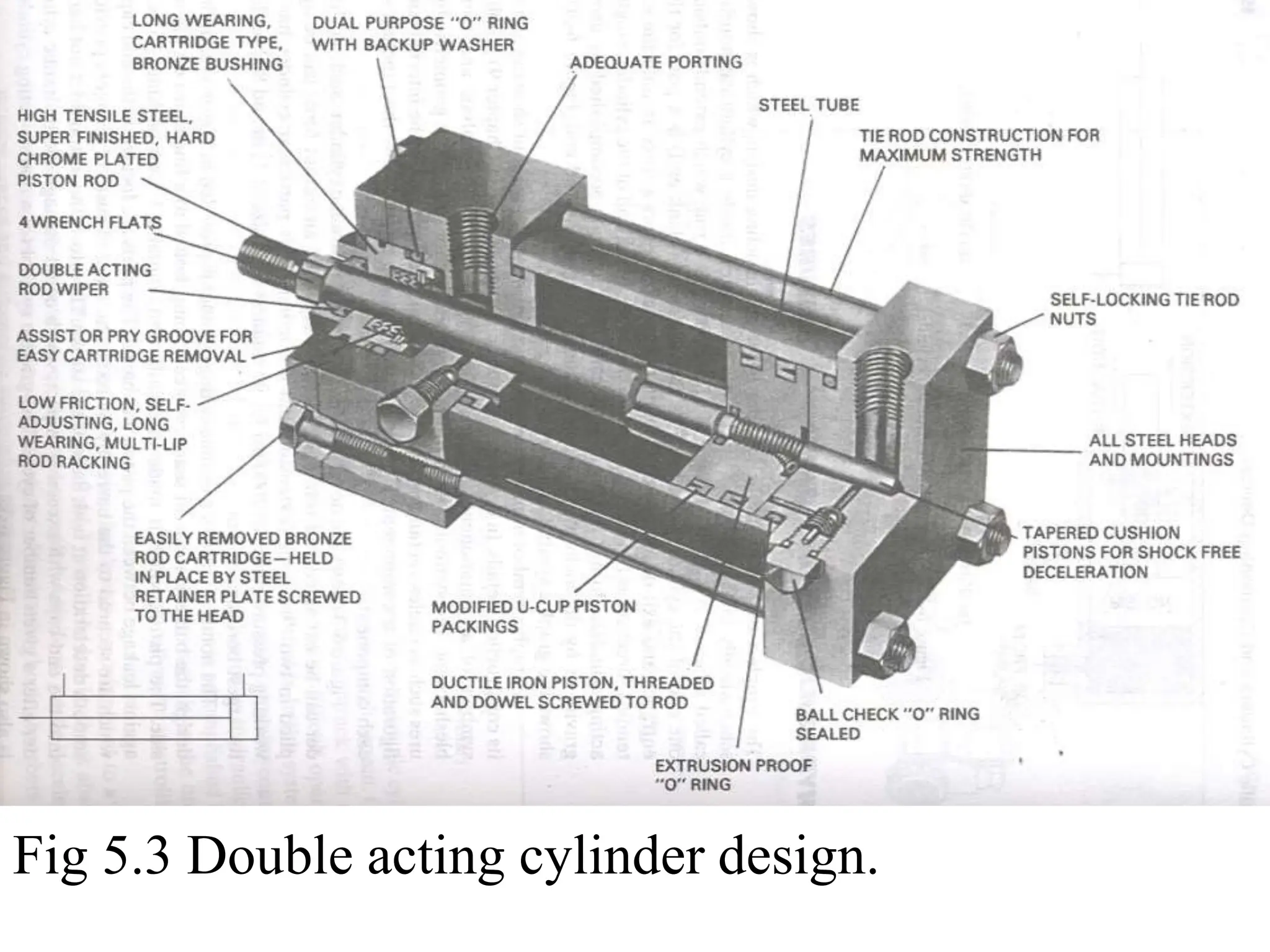
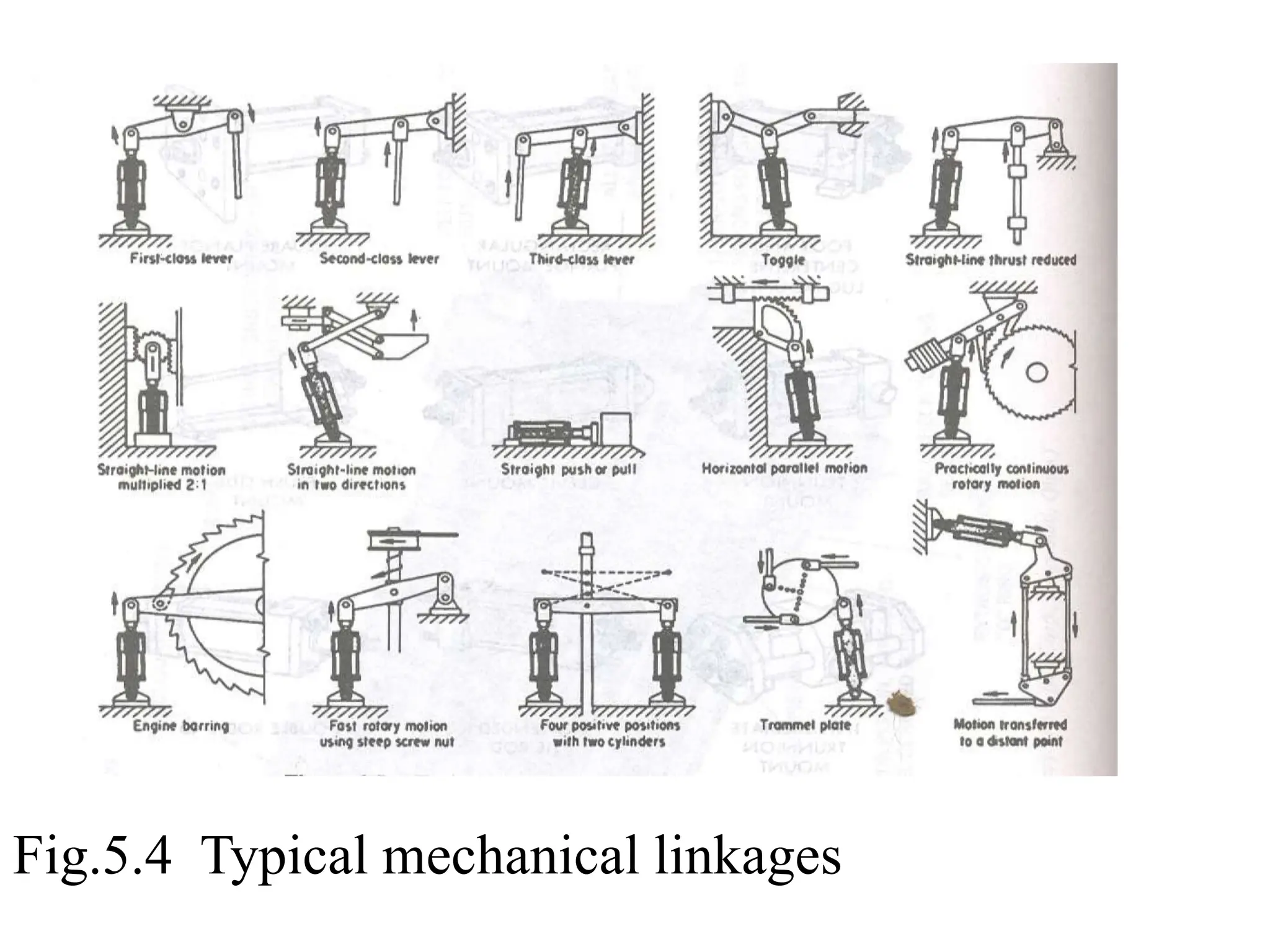
This document discusses actuators used in hydraulic systems. It covers hydraulic cylinders, which convert pressurized fluid into linear motion, and hydraulic motors, which provide rotary motion. Cylinders are either single-acting or double-acting, and their output force depends on piston area. Motors can provide either limited rotation or continuous rotation, with gear, vane, and piston designs described. Linkages are also discussed for transmitting cylinder forces to loads at different angles and magnitudes.
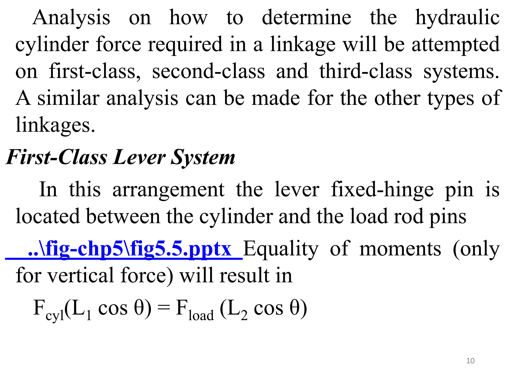
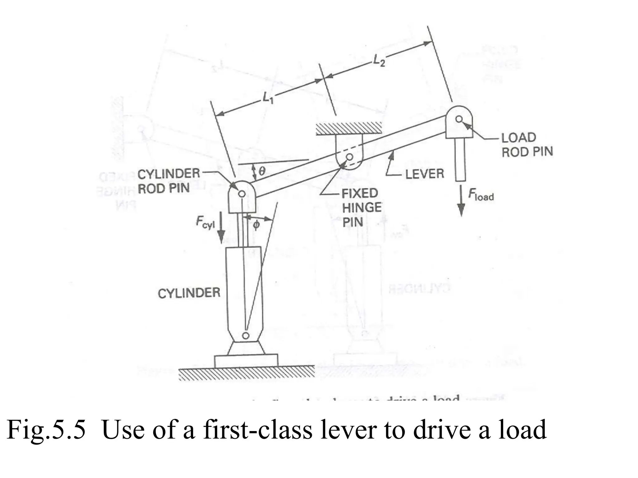
![This will give
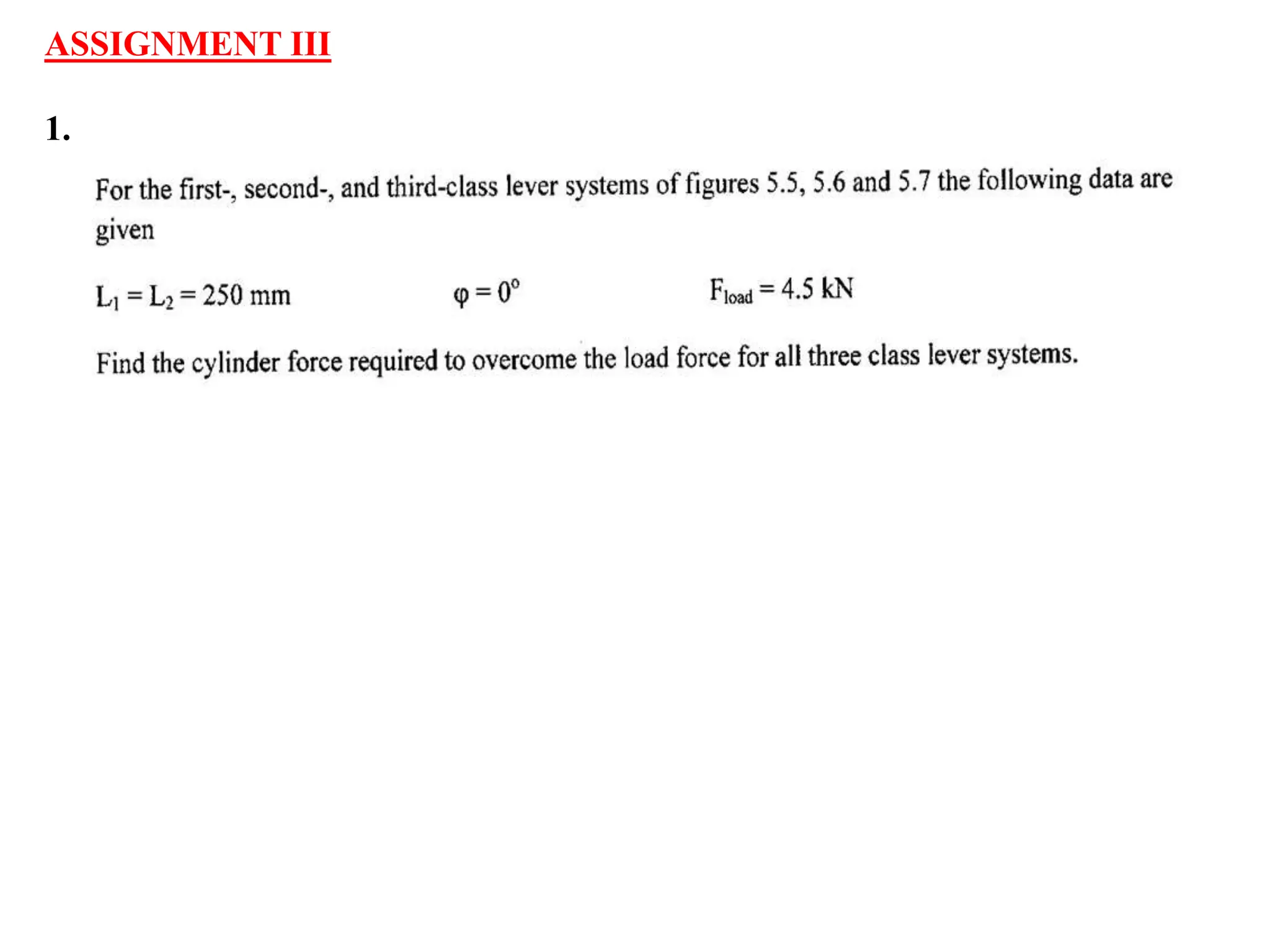
Fcyl = (L2/L1) Fload
But as shown in the figure the cylinder is mounted
to allow the rod-pinned end travel along a circular
path of radius L2 about its fixed-hinge pin. If the
cylinder is offset by an angle φ from the vertical, the
equation will change to
Fcyl(L1 cos θ . cos φ) = Fload (L2 cos θ)
which will give
Fcyl = [L2/(L1 cos φ)]Fload
11](https://image.slidesharecdn.com/chapter5fpspresente-240320074133-6803cea4/75/chapter_5_-fluid-power-system-lecture-note-pptx-11-2048.jpg)


![chapterfive [Autosaved].ppt](https://cdn.slidesharecdn.com/ss_thumbnails/chapterfiveautosaved-221227191443-4b610bb9-thumbnail.jpg?width=640&height=640&fit=bounds)


