Downloaded 6,893 times


![[2a] Circuit with brake valve
(Animation)](https://image.slidesharecdn.com/jj512basichydrauliccircuit-121222093438-phpapp01/85/Basic-hydraulic-circuit-31-320.jpg)
![[2b] Circuit with brake valve
(Animation)](https://image.slidesharecdn.com/jj512basichydrauliccircuit-121222093438-phpapp01/85/Basic-hydraulic-circuit-32-320.jpg)


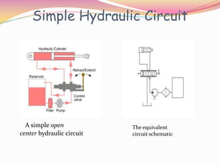
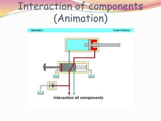
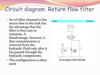
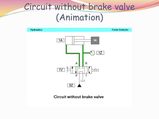
This document provides an overview of basic hydraulic circuits. It describes how hydraulic systems are divided into a signal control section and a hydraulic power section. The power section includes a pump, valves to control fluid flow and pressure, and hydraulic cylinders or motors. Simple circuits are shown including a pump, directional control valve, cylinder, and pressure relief valve. The interactions of these components in a basic circuit are illustrated through animations. Additional diagrams demonstrate uses of filters, contamination indicators, and pressure relief valves, including how a brake valve is used to prevent pressure spikes when a directional control valve closes suddenly.


