Download as PDF, PPTX
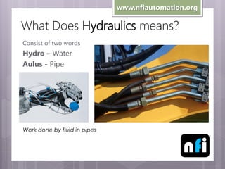
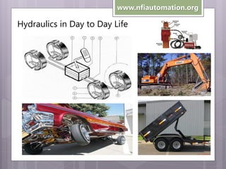
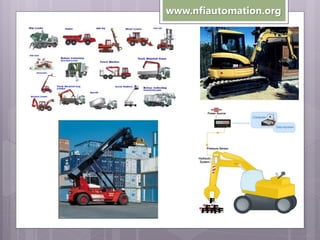
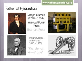
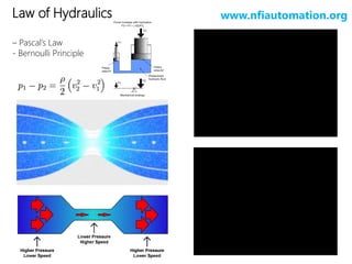
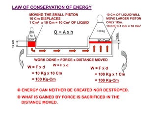
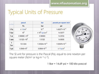

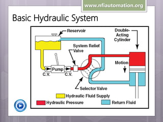
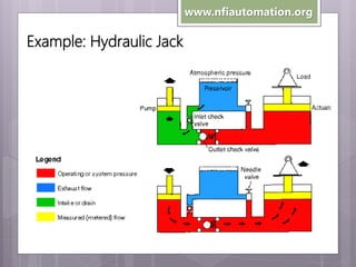
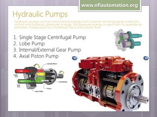
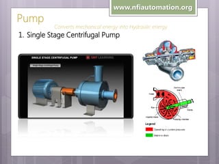
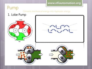
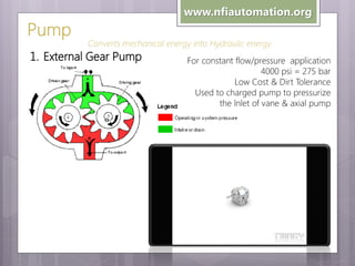
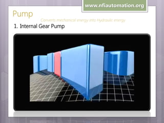
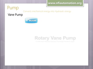

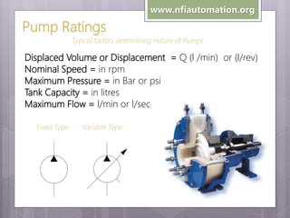
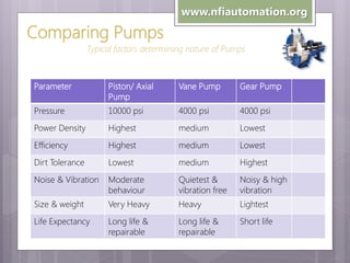

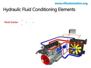
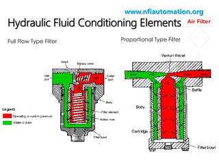
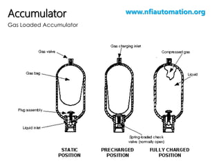
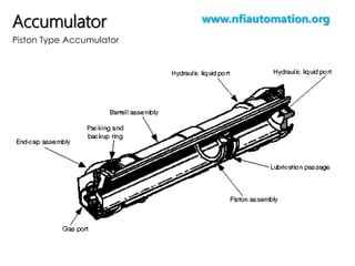
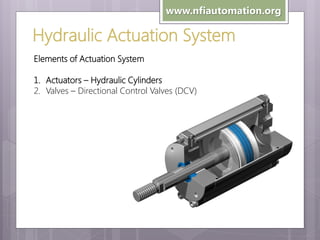
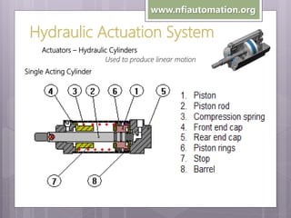
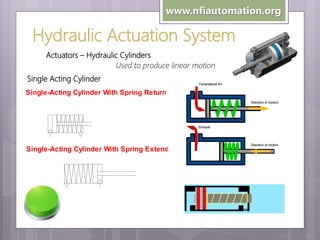
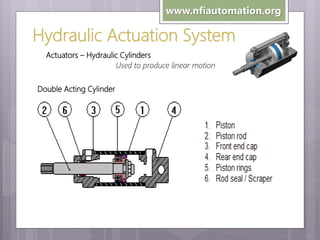
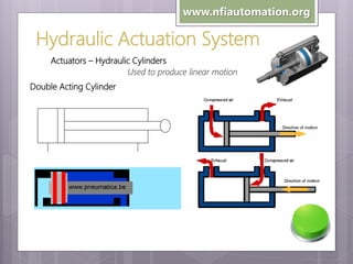
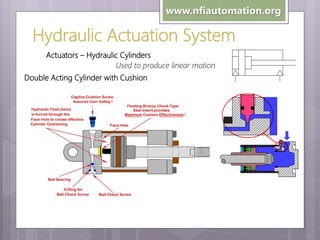
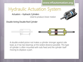
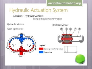
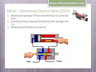

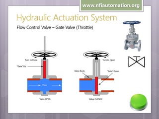
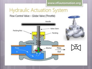
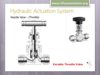


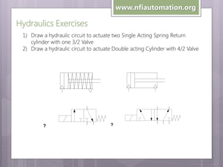
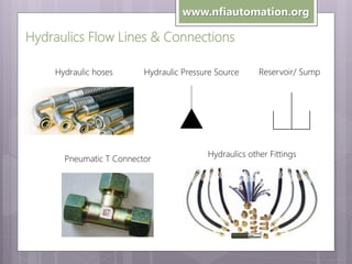
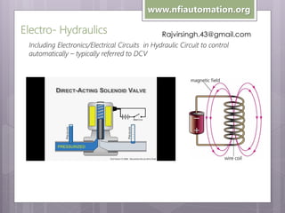

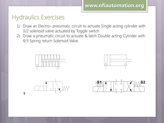
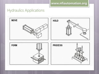
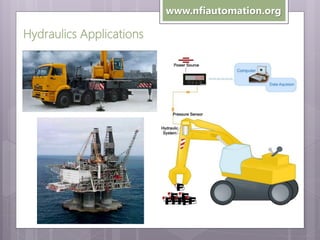


The document provides an overview of industrial hydraulics, including: - The definition and etymology of hydraulics. - Examples of hydraulics in everyday life and basic hydraulic systems like hydraulic jacks. - Key figures in the development of hydraulics like Joseph Bramah. - Fundamental hydraulic principles like Pascal's law. - Components of hydraulic systems like pumps, valves, actuators, and fluid conditioning elements. - Types of hydraulic pumps, cylinders, motors, and directional control valves.


