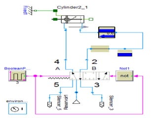
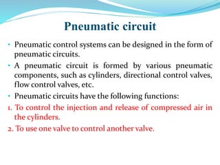
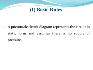
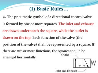
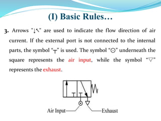
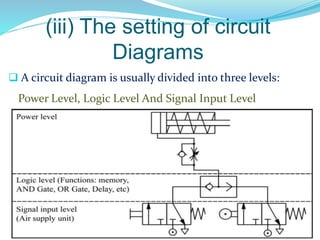
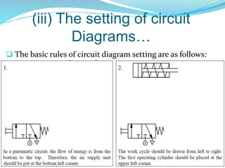
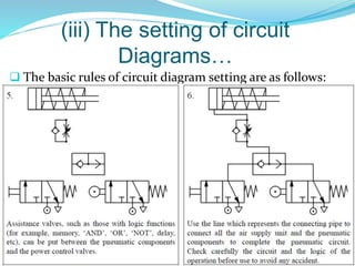
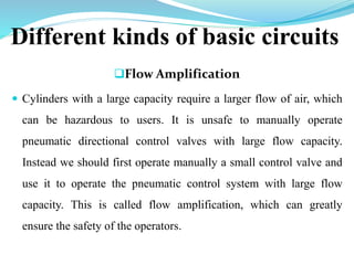
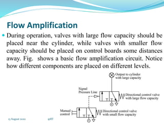
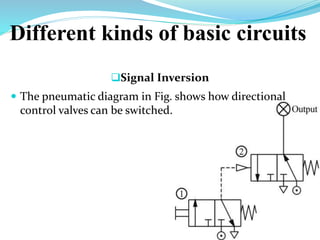
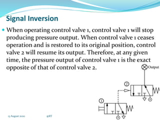
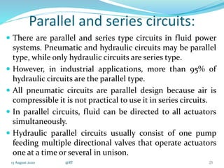
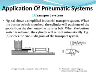
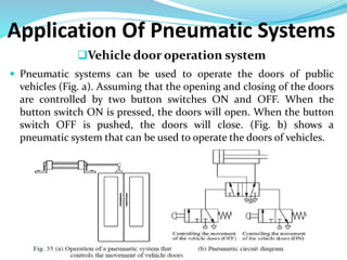
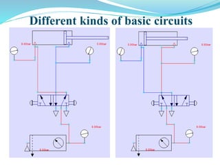
CHAPTER 7
Pneumatic circuits
13 August 2020 @RT 1
Prepared by : Prof. Rahul Thaker
Department of Mechanical Engineering
Alpha College of Engineering & Technology
Pneumatic circuit
• Pneumatic control systems can be designed in the form of
pneumatic circuits.
• A pneumatic circuit is formed by various pneumatic
components, such as cylinders, directional control valves,
flow control valves, etc.
• Pneumatic circuits have the following functions:
1. To control the injection and release of compressed air in
the cylinders.
2. To use one valve to control another valve.
Pneumatic circuit diagram
 A pneumatic circuit diagram uses pneumatic symbols
to describe its design.
 Some basic rules must be followed when drawing
pneumatic diagrams.
(I) Basic Rules
1. A pneumatic circuit diagram represents the circuit in
static form and assumes there is no supply of
pressure.
(I) Basic Rules…
2. The pneumatic symbol of a directional control valve
is formed by one or more squares. The inlet and exhaust
are drawn underneath the square, while the outlet is
drawn on the top. Each function of the valve (the
position of the valve) shall be represented by a square. If
there are two or more functions, the squares should be
arranged horizontally
3. Arrows "↓↖" are used to indicate the flow direction of air
current. If the external port is not connected to the internal
parts, the symbol “┬” is used. The symbol “⊙” underneath the
square represents the air input, while the symbol “▽”
represents the exhaust.
(I) Basic Rules…
(I) Basic Rules…
4. The pneumatic symbols of operational components should be
drawn on the outside of the squares. They can be divided into
two classes: mechanical and manual.
Mechanically operated pneumatic components
Manually operated pneumatic components
(I) Basic Rules…
5. Pneumatic operation signal pressure lines should be
drawn on one side of the squares, while triangles are used to
represent the direction of air flow
Pneumatic operation signal pressure line
(II) Basic principles
1. When the manual switch is not
operated, the spring will restore
the valve to its original position.
2. From the position of the spring,
one can deduce that the block is
operating. The other block will not
operate until the switch is pushed.
3. Air pressure exists along this line
because it is connected to the
source of compressed air.
(II) Basic principles
3. As this cylinder cavity and
piston rod are under the
influence of pressure, the piston
rod is in its restored position.
4. The rear cylinder cavity and
this line are connected to the
exhaust, where air is released.
(iii) The setting of circuit
Diagrams
 A circuit diagram is usually divided into three levels:
Power Level, Logic Level And Signal Input Level
(iii) The setting of circuit
Diagrams…
 The basic rules of circuit diagram setting are as follows:
(iii) The setting of circuit
Diagrams…
 The basic rules of circuit diagram setting are as follows:
(iii) The setting of circuit
Diagrams…
 The basic rules of circuit diagram setting are as follows:
Hydraulic and pneumatic
circuit:
Design Considerations :
Safety of Operation :
1. Pressure and Temperature ratings.
2. Interlocks for sequential operations
3. Emergency shutdown features
4. Power failure locks.
5. Operation speed.
6. Environment conditions.
13 August 2020 @RT 17
Meet functional requirements :
1. Meet required performance specification.
2. Life expectancy same as machine.
3. Facilitate good maintenance practice.
4. Compatibility with electrical and mechanical
components.
5. Withstand operational hazards.
13 August 2020 @RT 18
Efficiency of Operation :
1. Keep system Simple, Safe and Functional.
2. Access to parts need repair or adjustment.
3. Design to keep min operational cost.
4. Design to prevent and remove contamination.
13 August 2020 @RT 19
Safety of Operation :
1. Pressure and Temperature ratings.
2. Interlocks for sequential operations
3. Emergency shutdown features.
4. Power failure locks
5. Operation speed.
6. Environment conditions.
13 August 2020 @RT 20
Different kinds of basic circuits
Flow Amplification
 Cylinders with a large capacity require a larger flow of air, which
can be hazardous to users. It is unsafe to manually operate
pneumatic directional control valves with large flow capacity.
Instead we should first operate manually a small control valve and
use it to operate the pneumatic control system with large flow
capacity. This is called flow amplification, which can greatly
ensure the safety of the operators.
Flow Amplification
 During operation, valves with large flow capacity should be
placed near the cylinder, while valves with smaller flow
capacity should be placed on control boards some distances
away. Fig. shows a basic flow amplification circuit. Notice
how different components are placed on different levels.
13 August 2020 @RT 22
Different kinds of basic circuits
Signal Inversion
 The pneumatic diagram in Fig. shows how directional
control valves can be switched.
Signal Inversion
 When operating control valve 1, control valve 1 will stop
producing pressure output. When control valve 1 ceases
operation and is restored to its original position, control
valve 2 will resume its output. Therefore, at any given
time, the pressure output of control valve 1 is the exact
opposite of that of control valve 2.
13 August 2020 @RT 24
Parallel and series circuits:
 There are parallel and series type circuits in fluid power
systems. Pneumatic and hydraulic circuits may be parallel
type, while only hydraulic circuits are series type.
 However, in industrial applications, more than 95% of
hydraulic circuits are the parallel type.
 All pneumatic circuits are parallel design because air is
compressible it is not practical to use it in series circuits.
 In parallel circuits, fluid can be directed to all actuators
simultaneously.
 Hydraulic parallel circuits usually consist of one pump
feeding multiple directional valves that operate actuators
one at a time or several in unison.
13 August 2020 @RT 25
Application Of Pneumatic Systems
Transport system
 Fig. (a) shows a simplified industrial transport system. When
the button switch is pushed, the cylinder will push one of the
goods from the shelf onto the transfer belt. When the button
switch is released, the cylinder will retract automatically. Fig.
(b) shows the circuit diagram of the transport system.
Application Of Pneumatic Systems
Vehicle door operation system
 Pneumatic systems can be used to operate the doors of public
vehicles (Fig. a). Assuming that the opening and closing of the doors
are controlled by two button switches ON and OFF. When the
button switch ON is pressed, the doors will open. When the button
switch OFF is pushed, the doors will close. (Fig. b) shows a
pneumatic system that can be used to operate the doors of vehicles.
Different kinds of basic circuits
ADVANTAGES AND
DISADVANTAGES Advantages:
very flexible , free-format syntax.
Supported by every product.
It can express arithmetic operations as well
as operations to aggregate data and sort data for
output.
 Disadvantages:
It is not a general-purpose programming
language and thus the development of an
application requires the use of a SQL with a
programming language.

Pneumatic circuits

  • 1.
    CHAPTER 7 Pneumatic circuits 13August 2020 @RT 1 Prepared by : Prof. Rahul Thaker Department of Mechanical Engineering Alpha College of Engineering & Technology
  • 4.
    Pneumatic circuit • Pneumaticcontrol systems can be designed in the form of pneumatic circuits. • A pneumatic circuit is formed by various pneumatic components, such as cylinders, directional control valves, flow control valves, etc. • Pneumatic circuits have the following functions: 1. To control the injection and release of compressed air in the cylinders. 2. To use one valve to control another valve.
  • 5.
    Pneumatic circuit diagram A pneumatic circuit diagram uses pneumatic symbols to describe its design.  Some basic rules must be followed when drawing pneumatic diagrams.
  • 6.
    (I) Basic Rules 1.A pneumatic circuit diagram represents the circuit in static form and assumes there is no supply of pressure.
  • 7.
    (I) Basic Rules… 2.The pneumatic symbol of a directional control valve is formed by one or more squares. The inlet and exhaust are drawn underneath the square, while the outlet is drawn on the top. Each function of the valve (the position of the valve) shall be represented by a square. If there are two or more functions, the squares should be arranged horizontally
  • 8.
    3. Arrows "↓↖"are used to indicate the flow direction of air current. If the external port is not connected to the internal parts, the symbol “┬” is used. The symbol “⊙” underneath the square represents the air input, while the symbol “▽” represents the exhaust. (I) Basic Rules…
  • 9.
    (I) Basic Rules… 4.The pneumatic symbols of operational components should be drawn on the outside of the squares. They can be divided into two classes: mechanical and manual. Mechanically operated pneumatic components Manually operated pneumatic components
  • 10.
    (I) Basic Rules… 5.Pneumatic operation signal pressure lines should be drawn on one side of the squares, while triangles are used to represent the direction of air flow Pneumatic operation signal pressure line
  • 11.
    (II) Basic principles 1.When the manual switch is not operated, the spring will restore the valve to its original position. 2. From the position of the spring, one can deduce that the block is operating. The other block will not operate until the switch is pushed. 3. Air pressure exists along this line because it is connected to the source of compressed air.
  • 12.
    (II) Basic principles 3.As this cylinder cavity and piston rod are under the influence of pressure, the piston rod is in its restored position. 4. The rear cylinder cavity and this line are connected to the exhaust, where air is released.
  • 13.
    (iii) The settingof circuit Diagrams  A circuit diagram is usually divided into three levels: Power Level, Logic Level And Signal Input Level
  • 14.
    (iii) The settingof circuit Diagrams…  The basic rules of circuit diagram setting are as follows:
  • 15.
    (iii) The settingof circuit Diagrams…  The basic rules of circuit diagram setting are as follows:
  • 16.
    (iii) The settingof circuit Diagrams…  The basic rules of circuit diagram setting are as follows:
  • 17.
    Hydraulic and pneumatic circuit: DesignConsiderations : Safety of Operation : 1. Pressure and Temperature ratings. 2. Interlocks for sequential operations 3. Emergency shutdown features 4. Power failure locks. 5. Operation speed. 6. Environment conditions. 13 August 2020 @RT 17
  • 18.
    Meet functional requirements: 1. Meet required performance specification. 2. Life expectancy same as machine. 3. Facilitate good maintenance practice. 4. Compatibility with electrical and mechanical components. 5. Withstand operational hazards. 13 August 2020 @RT 18
  • 19.
    Efficiency of Operation: 1. Keep system Simple, Safe and Functional. 2. Access to parts need repair or adjustment. 3. Design to keep min operational cost. 4. Design to prevent and remove contamination. 13 August 2020 @RT 19
  • 20.
    Safety of Operation: 1. Pressure and Temperature ratings. 2. Interlocks for sequential operations 3. Emergency shutdown features. 4. Power failure locks 5. Operation speed. 6. Environment conditions. 13 August 2020 @RT 20
  • 21.
    Different kinds ofbasic circuits Flow Amplification  Cylinders with a large capacity require a larger flow of air, which can be hazardous to users. It is unsafe to manually operate pneumatic directional control valves with large flow capacity. Instead we should first operate manually a small control valve and use it to operate the pneumatic control system with large flow capacity. This is called flow amplification, which can greatly ensure the safety of the operators.
  • 22.
    Flow Amplification  Duringoperation, valves with large flow capacity should be placed near the cylinder, while valves with smaller flow capacity should be placed on control boards some distances away. Fig. shows a basic flow amplification circuit. Notice how different components are placed on different levels. 13 August 2020 @RT 22
  • 23.
    Different kinds ofbasic circuits Signal Inversion  The pneumatic diagram in Fig. shows how directional control valves can be switched.
  • 24.
    Signal Inversion  Whenoperating control valve 1, control valve 1 will stop producing pressure output. When control valve 1 ceases operation and is restored to its original position, control valve 2 will resume its output. Therefore, at any given time, the pressure output of control valve 1 is the exact opposite of that of control valve 2. 13 August 2020 @RT 24
  • 25.
    Parallel and seriescircuits:  There are parallel and series type circuits in fluid power systems. Pneumatic and hydraulic circuits may be parallel type, while only hydraulic circuits are series type.  However, in industrial applications, more than 95% of hydraulic circuits are the parallel type.  All pneumatic circuits are parallel design because air is compressible it is not practical to use it in series circuits.  In parallel circuits, fluid can be directed to all actuators simultaneously.  Hydraulic parallel circuits usually consist of one pump feeding multiple directional valves that operate actuators one at a time or several in unison. 13 August 2020 @RT 25
  • 26.
    Application Of PneumaticSystems Transport system  Fig. (a) shows a simplified industrial transport system. When the button switch is pushed, the cylinder will push one of the goods from the shelf onto the transfer belt. When the button switch is released, the cylinder will retract automatically. Fig. (b) shows the circuit diagram of the transport system.
  • 27.
    Application Of PneumaticSystems Vehicle door operation system  Pneumatic systems can be used to operate the doors of public vehicles (Fig. a). Assuming that the opening and closing of the doors are controlled by two button switches ON and OFF. When the button switch ON is pressed, the doors will open. When the button switch OFF is pushed, the doors will close. (Fig. b) shows a pneumatic system that can be used to operate the doors of vehicles.
  • 28.
    Different kinds ofbasic circuits
  • 29.
    ADVANTAGES AND DISADVANTAGES Advantages: veryflexible , free-format syntax. Supported by every product. It can express arithmetic operations as well as operations to aggregate data and sort data for output.  Disadvantages: It is not a general-purpose programming language and thus the development of an application requires the use of a SQL with a programming language.