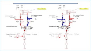
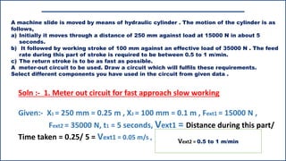
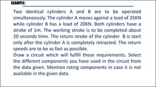
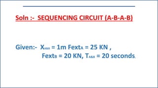
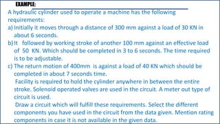
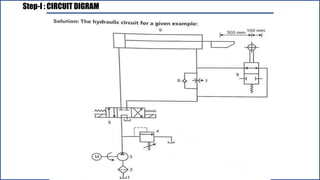
The document provides requirements for designing a hydraulic system for moving a machine slide. It includes:
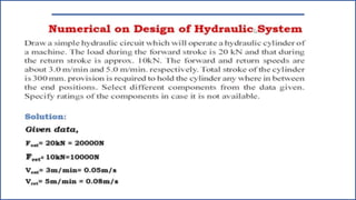
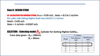
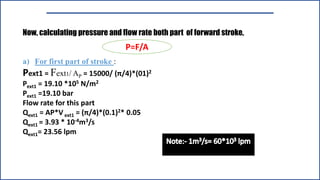
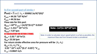
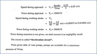
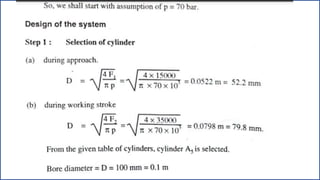
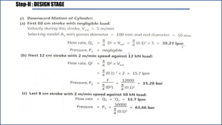
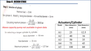
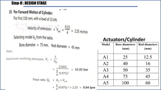
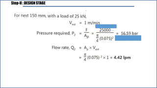
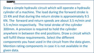
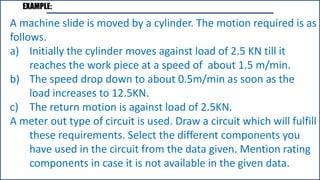
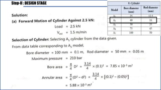
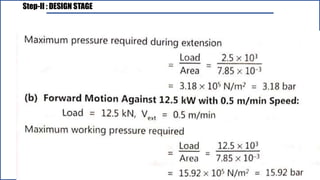
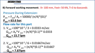
1) The slide moves 250mm against a 15,000N load in 5 seconds, followed by a 100mm working stroke against 35,000N load at 0.5-1m/min.
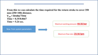
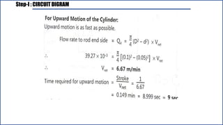
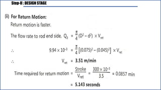
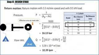
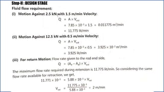
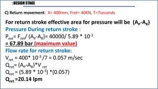
2) The return stroke should be as fast as possible.
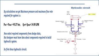
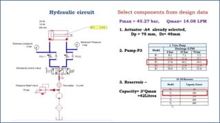
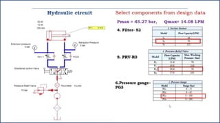
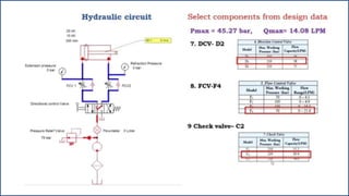
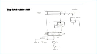
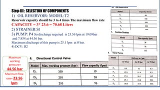
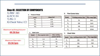
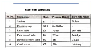
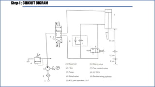
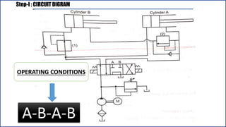
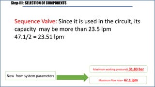
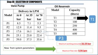
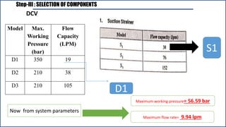
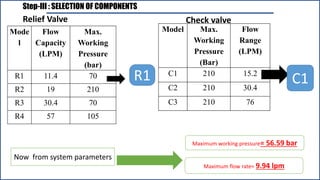
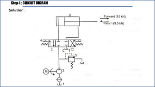
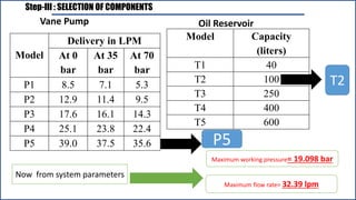
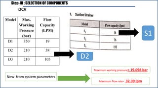
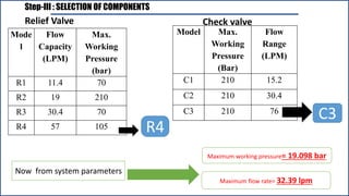
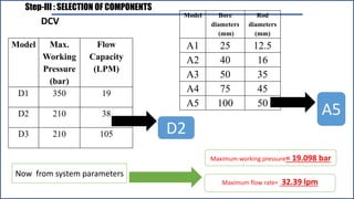
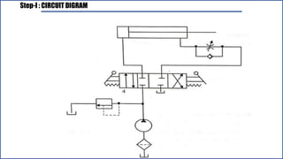
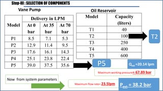
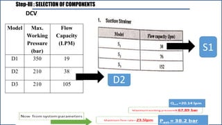
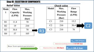
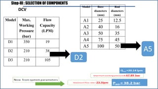
3) A meter-out circuit is required to meet the specifications. Components should be selected from the data provided.