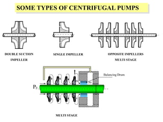
CHAPTER 1
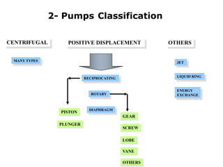
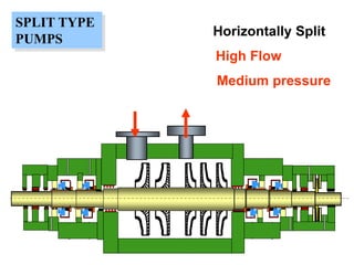
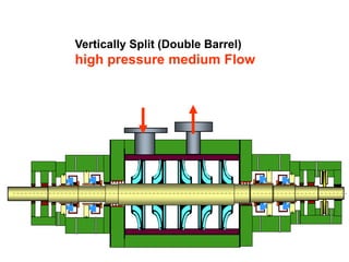
2- PumpsClassification
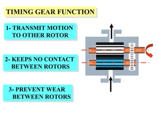
1- Function Of Pumps
3-Code and Standards
3.
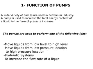
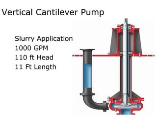
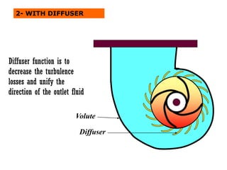
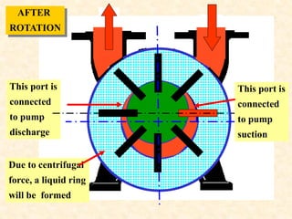
A wide varietyof pumps are used in petroleum industry.
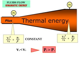
A pump is used to increase the total energy content of
a liquid in the form of pressure increase.
-Move liquids from low level to high level
-Move liquids from low pressure location
to high pressure location
-Hydraulic Systems
-To increase the flow rate of a liquid
1- FUNCTION OF PUMPS
The pumps are used to perform one of the following jobs:
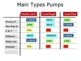
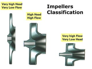
Main Types Pumps
HIGHLOW
V. HIGH
NO NO
YES
LOW HIGH V. HIGH
YES NO NO
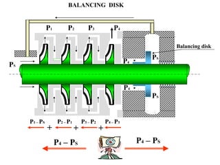
Pressure P
Flow Rate Q
S .R .V
Efficiency
Maint. cost
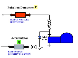
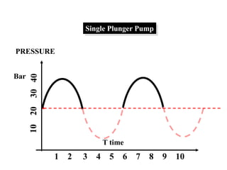
Pulsation
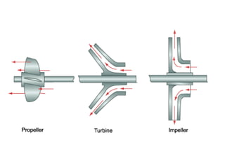
Positive D.P. Centrifugal Axial Flow
V. HIGH LOW LOW
HIGH MEDIUM V. HIGH
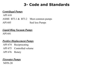
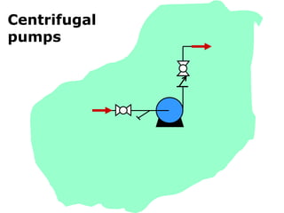
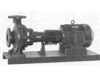
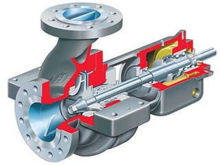
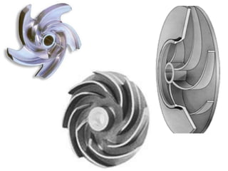
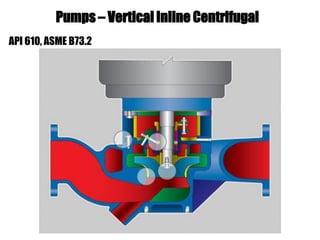
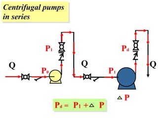
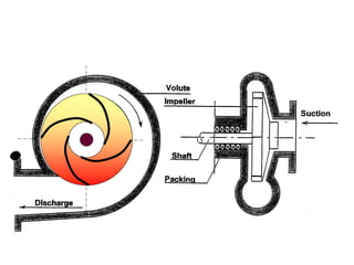
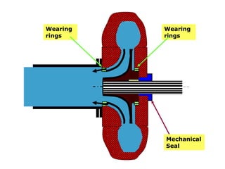
Centrifugal Pumps
API 610
ASMEB73.1 & B73.2 Most common pumps
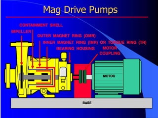
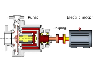
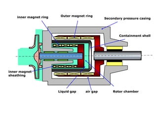
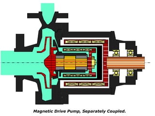
API 685 Seal less Pumps
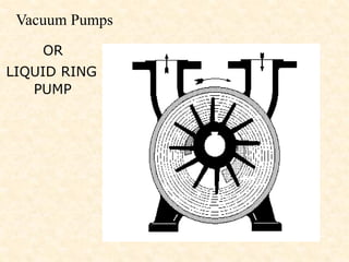
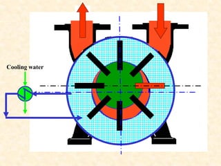
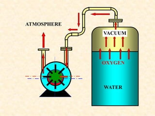
Liquid Ring Vacuum Pumps
API 681
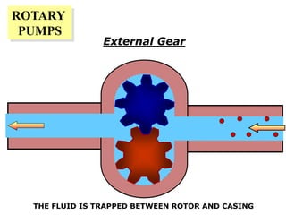
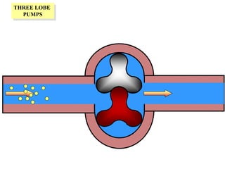
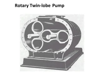
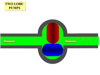
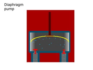
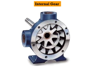
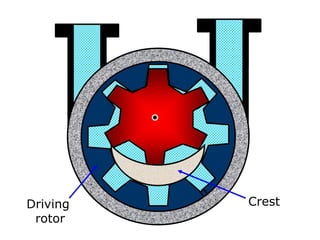
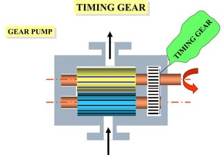
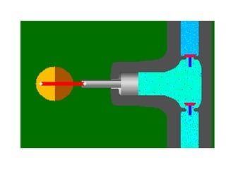
Positive Displacement Pumps
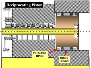
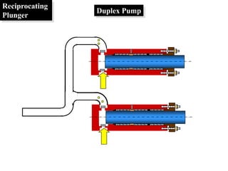
API 674 Reciprocating
API 675 Controlled volume
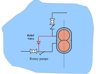
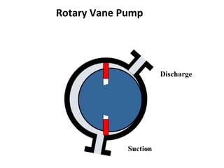
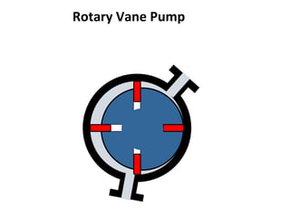
API 676 Rotary
Firewater Pumps
NFPA 20
3- Code and Standards
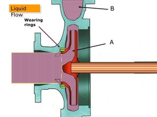
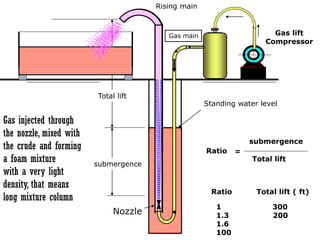
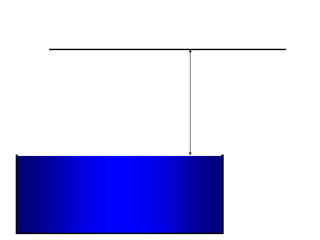
submergence
Total lift
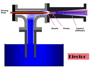
Nozzle
Gas main
Risingmain
Standing water level
submergence
Total lift
=
Ratio
1 300
1.3 200
1.6
100
Ratio Total lift ( ft)
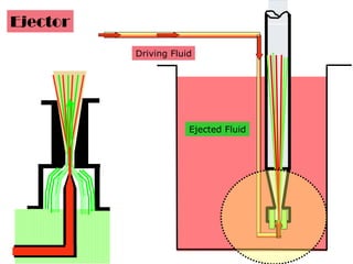
Gas lift
Compressor
Gas injected through
the nozzle, mixed with
the crude and forming
a foam mixture
with a very light
density, that means
long mixture column
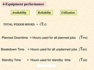
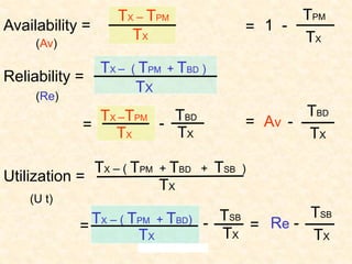
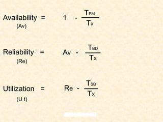
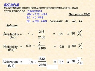
Planned Downtime =Hours used for all planned jobs (TPM)
Breakdown Time = Hours used for all unplanned jobs (TBD)
Standby Time = Hours used for standby time (TSB)
4-Equipment performance
Availability Reliability Utilization
Total Period Hours = (TX)
1 (PSI) =2.31 (Ft)
Pressure = Head (Ft ) x (SG) / 2.31 (PSI)
Water 231 Ft x 1.0 / 2.31 = 100 PSI
HCL 231 Ft x 1.2 / 2.31 = 120 PSI
Gas oil 231 Ft x 0.80 / 2.31 = 80 PSI
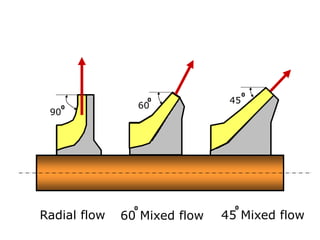
Gas
oil
For water
105.
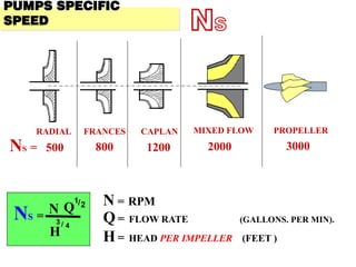
FRANCES
RADIAL CAPLAN MIXEDFLOW PROPELLER
NS = 500 800 1200 2000 3000
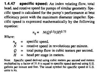
NS =
Q
1/2
H
3 / 4
N
Q= FLOW RATE (GALLONS. PER MIN).
H= HEAD PER IMPELLER (FEET )
N = RPM
PUMPS SPECIFIC
SPEED NS
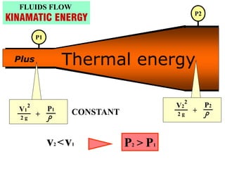
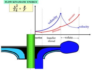
H
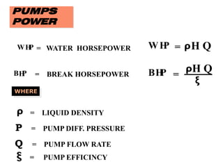
P
W = HQ
ρ
H
P
B =
H Q
ξ
ρ
H
P
W = WATER HORSEPOWER
ρ = LIQUID DENSITY
P = PUMP DIFF. PRESSURE
Q = PUMP FLOW RATE
ξ = PUMP EFFICINCY
= BREAK HORSEPOWER
BH
P
WHERE
PUMPS
POWER
H
P
W = PQ
0.00058
P = p s i
Q = GPM
H
P
W = P Q
0.037
P = bar
Q = M
3
hr
HP
B = P Q
ξ
0.037
HP
B = P Q
ξ
0.00058
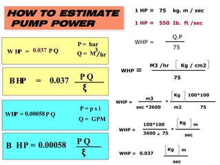
HOW TO ESTIMATE
PUMP POWER
1 HP = 75 kg. m / sec
1 HP = 550 Ib. ft /sec
WHP =
Q.P
75
WHP =
75
Kg / cm2
M3 /hr
WHP =
75
Kg
m3
sec *3600
*
100*100
m2
WHP =
75
Kg
3600
*
100*100 m
sec
*
WHP =
Kg
0.037
m
sec
112.
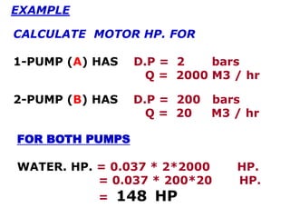
FOR BOTH PUMPS
WATER.HP. = 0.037 * 2*2000 HP.
= 0.037 * 200*20 HP.
= 148 HP
EXAMPLE
CALCULATE MOTOR HP. FOR
1-PUMP (A) HAS D.P = 2 bars
Q = 2000 M3 / hr
2-PUMP (B) HAS D.P = 200 bars
Q = 20 M3 / hr
113.
500 1000 15002000 2500 3000
0.1
0.2
0.3
0.4
0.5
0.6
0.7
0.8
0.9
1.0
ξ
50
30
10 GPM
3000
500
300
200
100
1000
10000 GPM
Q
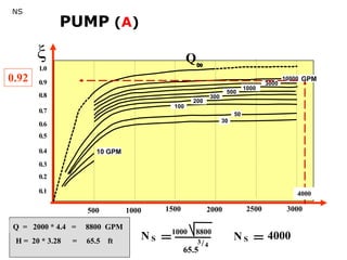
0.92
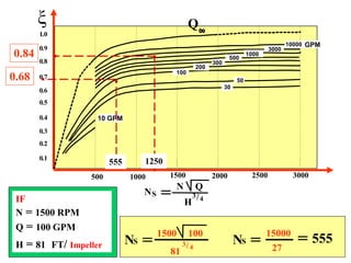
NS
Q = 2000 * 4.4 = 8800 GPM
H = 20 * 3.28 = 65.5 ft
4000
N S
1000 8800
65.5
3/4
N S 4000
PUMP (A)
114.
BRAKE HP =148 /0.92 = 160 HP.
Motor HP = 160*1.25 = 200 HP
PUMP A
NS =
Q
1/2
H
3 / 4
N
N = 1000 RPM
D.P = 2O*3.28 = 65.5 ft
Q = 2000*4.4 = 8800 GPM
NS = 1000 * 8800
1/2
65.5
3/4
=
1000 * 93.8
23
4000
=
ξ = 0.92
115.
N S
1000 88
655
3/4
5001000 1500 2000 2500 3000
0.1
0.2
0.3
0.4
0.5
0.6
0.7
0.8
0.9
1.0
ξ
50
30
10 GPM
3000
500
300
200
100
1000
10000 GPM
Q
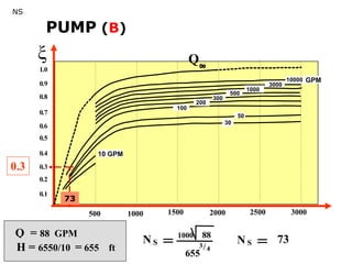
0.3
NS
Q = 88 GPM
H = 6550/10 = 655 ft
N S 73
73
PUMP (B)
116.
BRAKE HP =148 /0.3 = 500 HP.
Motor HP = 500 * 1.25 = 625 HP
PUMP B
NS =
Q
1/2
H
3 / 4
N
N = 1000 RPM
D.P = 2O00*3.28 = 6550 ft
D.P/impeller (10 imp) = 655 ft
Q = 20*4.4 = 88 GPM
NS = 1000 * 88
1/2
655
3/4
=
1000 * 9.38
130
73
=
ξ = 0.3
117.
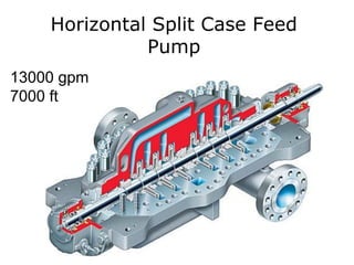
Q 5000 gpmBHP 1818
P/stage 169 psi MHP 2182
N 1800 rpm
H/stage 391 ft Ns 1448
ξ 0.81
END PRESSURE 500 psi
D.P. 507.8 psi
n 3 stages
ELEVATION/2.31 5 psi
EFFICIENCY AS A FUNCTION OF SPECIFIC SPEED AND CAPACITY
0.1
0.2
0.3
0.4
0.5
0.6
0.7
0.8
0.9
1.0
500 1000 1500 2000 2500 3000
50
30
10 GPM
5
10000
3000
500
1000
300
200
100
N S
GPM
0.81
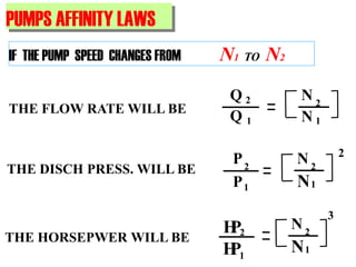
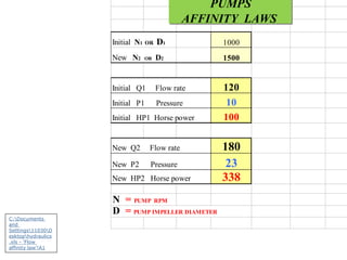
THE FLOW RATEWILL BE
Q 2
Q 1
N 2
1
N
IF THE PUMP SPEED CHANGES FROM N1 TO N2
PUMPS AFFINITY LAWS
THE DISCH PRESS. WILL BE
2
P2
P1
N2
1
N
THE HORSEPWER WILL BE
3
N2
1
N
2
1
P
H
P
H