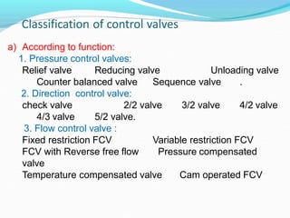
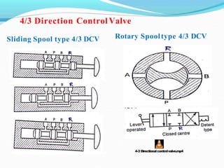
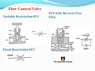
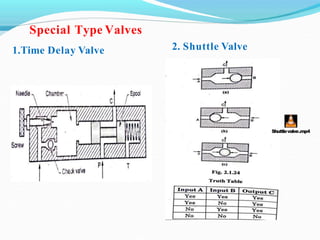
a) According to function:
1. Pressure control valves:
Relief valve Reducing valve Unloading valve
Sequence valve .
Counter balanced valve
2. Direction control valve:
check valve
4/3 valve
2/2 valve 3/2 valve 4/2 valve
5/2 valve.
Variable restriction FCV
Pressure compensated
3. Flow control valve :
Fixed restriction FCV
FCV with Reverse free flow
valve
Temperature compensated valve Cam operated FCV
b) According to the method actuation:
1. Manual operated:
Palm operated Push button operated
operated
Hand lever operated. Foot pedal
Cam(roller) operated
b.Double pilot.
2.Pilot operated:
a.Single pilot
3.Solenoid operated:
Single solenoid Double solenoid.
c) According to construction:
1. Poppet type:
2. Spool type:
Ball type, conical poppet type.
Sliding spool type, rotary spool type.
3. Flow control : Gate valve, plug valve, needle valve, poppet
valve, butterfly valve etc.
1. Flow rate of oil.
2. Pressure of oil.
3. Force required by cylinder.
4. Speed of operation of cylinder
5. Type of actuation of the valve.
6. Port size.
7. Space requirement.
8. Temperature of oil
9.Oil under pressure compatibility.
10.Environment conditions.
Pressure Relief Valve Pressure Reducing Valve
PressureReliefValves.mp4
PressureReducingValve-Pilot Operated.mp4
Comparison between Pressure Relief Valve and Pressure
Reducing Valve
Unloading Valve
UnloadingValveBasics.mp4
Comparison between Pressure Relief Valve and
Unloading Valve
Counter Balance Valve Sequence Valve
a) According to the method actuation:
1. Manual operated:
Push button operated
Foot pedal operated Cam(roller)
b.Double pilot.
Double solenoid.
Palm operated
Hand lever operated.
operated
2. Pilot
operated:
a.Single pilot
3. Solenoid operated:
Single solenoid
b) According to ype of spool:
1. Poppet type.
2. Sliding Spool type.
3. Rotary spool type.
a)According to number of ports and position:
3/2 valve 4/2 valve
check valve
4/3 valve
2/2 valve
5/2 valve.
Check Valve
CheckValveAnimation.mp4
Sliding Spool type 2/2 DCV Rotary Spooltype 2/2 DCV
2/2 Direction Control Valve
Sliding Spool type 3/2 DCV Rotary Spool type3/2 DCV
3/2 Direction Control Valve
usinga32valveNO tocontrolacylinder.mp4
Sliding Spool type 4/2 DCV Rotary Spool type 4/2 DCV
4/2 Direction ControlValve
4-2 Directionalcontrolvalve.mp4 rotaryspooldirectionalvalves work.mp4
Sliding Spool type 4/3 DCV Rotary Spooltype 4/3 DCV
4/3 Direction Control Valve
4-3 Directionalcontrolvalve.mp4
Sliding Spool type 5/5 DCV Rotary Spool type5/2 DCV
5/2 Direction Control Valve
52valve.mp4
Method of Actuation and there Symbol
Variable Restriction FCV
FCVwith Reverse Free
Flow
Flow Control Valve
Fixed Restriction FCV
Flowcontrolvalves work.mp4
Pressure &Temp.
Compensated FCV
Cam operated FCVwith
integral check valve
PressureCompensatedValve- Part2.mp4
Camshaft_ ValveAnimation.mp4
1.Time Delay Valve 2. Shuttle Valve
Special Type Valves
Shuttlevalve.mp4
3.Twin Pressure Valve 4. Pilot Operated check
valve (Open &Closed)
Special Type Valves
PilotOperatedReliefValve Animation.mp4
3/2 Poppet type Direction
Control Valve
Comparison
Classification of Actuators 2. Rotating Cylinder
Single acting cylinder Double acting cylinder
SingleActingCylinder.mp4
DoubleActingCylinder.mp4
Diaphragm cylinder Double rod end cylinder
DiaphragmCylinder.mp4
Tandem cylinder Cylinder with cushioning
TandemCylinder.mp4
Telescope cylinder Cylinder Mountings
Telescopiccylinder2.mp4
A) Vane type
B) Piston type(Rack and
pinion type
Rotary Actuators
PistontypeActuator.mp4
External Gear Motor Radial Piston Motor
EXTERNALGEARPUMP.mp4
InternalGearPump.3gp
Gerotor Motor Vane type Motor
GerotorOperation.mp4
Axial PistonMotor
SWASHPLATEPISTONPUMP.mp4
Flexible Hose
a) Rigid pipe:
Cast iron, Low carbon steel, Alloy steels, stainless
steel, Copper and its alloy, Aluminum and its alloy.
b) Flexible hoses :
Nylon braided hoses, steel wire reinforced rubber
hoses, poly-urethene tubes, Nylon tubes, polyethylene
tubes, PVC tubes, polypropylene etc.
a)According to strength:
Standard pipe (STD), Extra strong pipe(XS),
Double Extra strong Pipe (XXS).
Flare-Less type fitting (Ferrulefitting)
a) According to method of sealing:
1. Positive seal: perfect seal, 100 % leak proof.
2. Non- positive seal: allow small amount of leakage.
b) According to application:
1. Steel seal : used between mating parts having no
relative motion.
E.g. sealing between flange, gasket etc.
2. Dynamic seal: used between mating parts with relative
motion.
E.g. rotary motion seal between pump shaft and casing.
a)According to shape configuration:
O-ring, quad-ring, T-ring, V-ring, U-cap, Hat ring etc.
Following are the reason for failure of hydraulic seals.
Excessive heat.
Excessive load.
Excessive clearance.
Excessive pressure.
Improper fitting.
Improper groove gravity.
Improper filter rating.
Contamination of fluid.
Idle storage of seals
Age hardening.
Abrasion.
A) Dead weight accumulator
B) Spring loaded
accumulator
Classification of accumulators:
C) Separator type accumulator
Accumulators: Circuit
A) Single acting Booster B) Double acting Booster
Pressure Boosters:

Control valve

  • 1.
    a) According tofunction: 1. Pressure control valves: Relief valve Reducing valve Unloading valve Sequence valve . Counter balanced valve 2. Direction control valve: check valve 4/3 valve 2/2 valve 3/2 valve 4/2 valve 5/2 valve. Variable restriction FCV Pressure compensated 3. Flow control valve : Fixed restriction FCV FCV with Reverse free flow valve Temperature compensated valve Cam operated FCV
  • 2.
    b) According tothe method actuation: 1. Manual operated: Palm operated Push button operated operated Hand lever operated. Foot pedal Cam(roller) operated b.Double pilot. 2.Pilot operated: a.Single pilot 3.Solenoid operated: Single solenoid Double solenoid. c) According to construction: 1. Poppet type: 2. Spool type: Ball type, conical poppet type. Sliding spool type, rotary spool type. 3. Flow control : Gate valve, plug valve, needle valve, poppet valve, butterfly valve etc.
  • 3.
    1. Flow rateof oil. 2. Pressure of oil. 3. Force required by cylinder. 4. Speed of operation of cylinder 5. Type of actuation of the valve. 6. Port size. 7. Space requirement. 8. Temperature of oil 9.Oil under pressure compatibility. 10.Environment conditions.
  • 4.
    Pressure Relief ValvePressure Reducing Valve PressureReliefValves.mp4 PressureReducingValve-Pilot Operated.mp4
  • 5.
    Comparison between PressureRelief Valve and Pressure Reducing Valve
  • 6.
  • 7.
    Comparison between PressureRelief Valve and Unloading Valve
  • 8.
    Counter Balance ValveSequence Valve
  • 9.
    a) According tothe method actuation: 1. Manual operated: Push button operated Foot pedal operated Cam(roller) b.Double pilot. Double solenoid. Palm operated Hand lever operated. operated 2. Pilot operated: a.Single pilot 3. Solenoid operated: Single solenoid b) According to ype of spool: 1. Poppet type. 2. Sliding Spool type. 3. Rotary spool type. a)According to number of ports and position: 3/2 valve 4/2 valve check valve 4/3 valve 2/2 valve 5/2 valve.
  • 10.
  • 11.
    Sliding Spool type2/2 DCV Rotary Spooltype 2/2 DCV 2/2 Direction Control Valve
  • 12.
    Sliding Spool type3/2 DCV Rotary Spool type3/2 DCV 3/2 Direction Control Valve usinga32valveNO tocontrolacylinder.mp4
  • 13.
    Sliding Spool type4/2 DCV Rotary Spool type 4/2 DCV 4/2 Direction ControlValve 4-2 Directionalcontrolvalve.mp4 rotaryspooldirectionalvalves work.mp4
  • 14.
    Sliding Spool type4/3 DCV Rotary Spooltype 4/3 DCV 4/3 Direction Control Valve 4-3 Directionalcontrolvalve.mp4
  • 15.
    Sliding Spool type5/5 DCV Rotary Spool type5/2 DCV 5/2 Direction Control Valve 52valve.mp4
  • 16.
    Method of Actuationand there Symbol
  • 17.
    Variable Restriction FCV FCVwithReverse Free Flow Flow Control Valve Fixed Restriction FCV Flowcontrolvalves work.mp4
  • 18.
    Pressure &Temp. Compensated FCV Camoperated FCVwith integral check valve PressureCompensatedValve- Part2.mp4 Camshaft_ ValveAnimation.mp4
  • 19.
    1.Time Delay Valve2. Shuttle Valve Special Type Valves Shuttlevalve.mp4
  • 20.
    3.Twin Pressure Valve4. Pilot Operated check valve (Open &Closed) Special Type Valves PilotOperatedReliefValve Animation.mp4
  • 21.
    3/2 Poppet typeDirection Control Valve Comparison
  • 22.
    Classification of Actuators2. Rotating Cylinder
  • 23.
    Single acting cylinderDouble acting cylinder SingleActingCylinder.mp4 DoubleActingCylinder.mp4
  • 24.
    Diaphragm cylinder Doublerod end cylinder DiaphragmCylinder.mp4
  • 25.
    Tandem cylinder Cylinderwith cushioning TandemCylinder.mp4
  • 26.
    Telescope cylinder CylinderMountings Telescopiccylinder2.mp4
  • 27.
    A) Vane type B)Piston type(Rack and pinion type Rotary Actuators PistontypeActuator.mp4
  • 28.
    External Gear MotorRadial Piston Motor EXTERNALGEARPUMP.mp4 InternalGearPump.3gp
  • 29.
    Gerotor Motor Vanetype Motor GerotorOperation.mp4
  • 30.
  • 31.
  • 32.
    a) Rigid pipe: Castiron, Low carbon steel, Alloy steels, stainless steel, Copper and its alloy, Aluminum and its alloy. b) Flexible hoses : Nylon braided hoses, steel wire reinforced rubber hoses, poly-urethene tubes, Nylon tubes, polyethylene tubes, PVC tubes, polypropylene etc. a)According to strength: Standard pipe (STD), Extra strong pipe(XS), Double Extra strong Pipe (XXS).
  • 33.
    Flare-Less type fitting(Ferrulefitting)
  • 34.
    a) According tomethod of sealing: 1. Positive seal: perfect seal, 100 % leak proof. 2. Non- positive seal: allow small amount of leakage. b) According to application: 1. Steel seal : used between mating parts having no relative motion. E.g. sealing between flange, gasket etc. 2. Dynamic seal: used between mating parts with relative motion. E.g. rotary motion seal between pump shaft and casing. a)According to shape configuration: O-ring, quad-ring, T-ring, V-ring, U-cap, Hat ring etc.
  • 35.
    Following are thereason for failure of hydraulic seals. Excessive heat. Excessive load. Excessive clearance. Excessive pressure. Improper fitting. Improper groove gravity. Improper filter rating. Contamination of fluid. Idle storage of seals Age hardening. Abrasion.
  • 36.
    A) Dead weightaccumulator B) Spring loaded accumulator Classification of accumulators: C) Separator type accumulator
  • 37.
  • 38.
    A) Single actingBooster B) Double acting Booster Pressure Boosters: