Download as PDF, PPTX
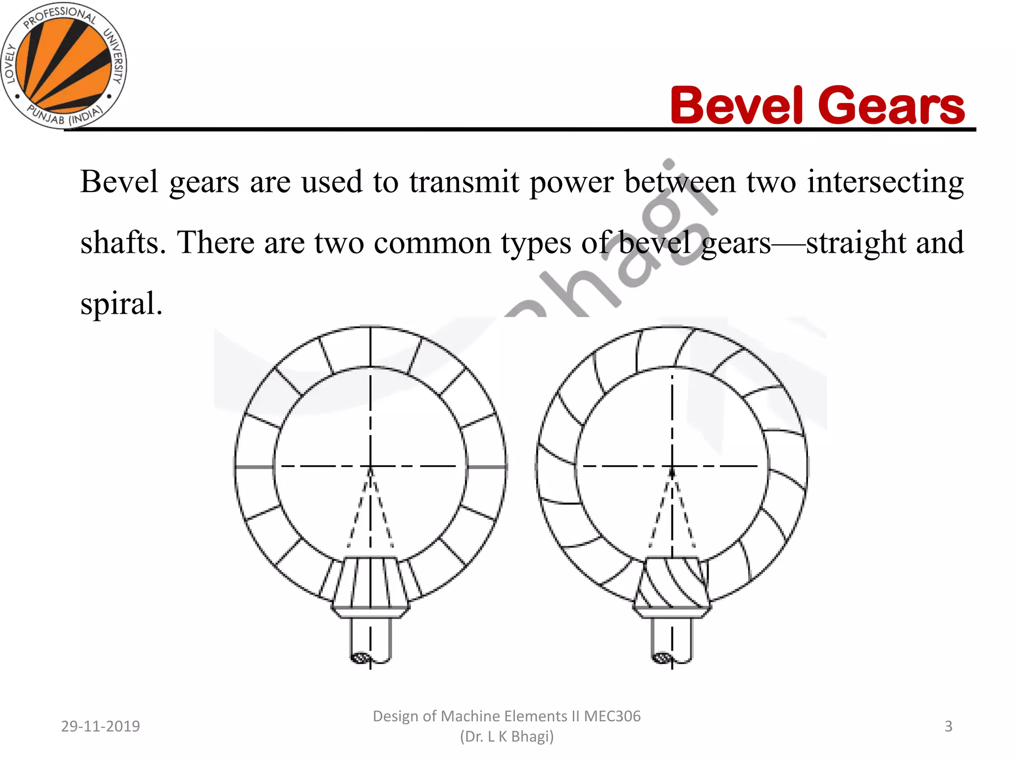
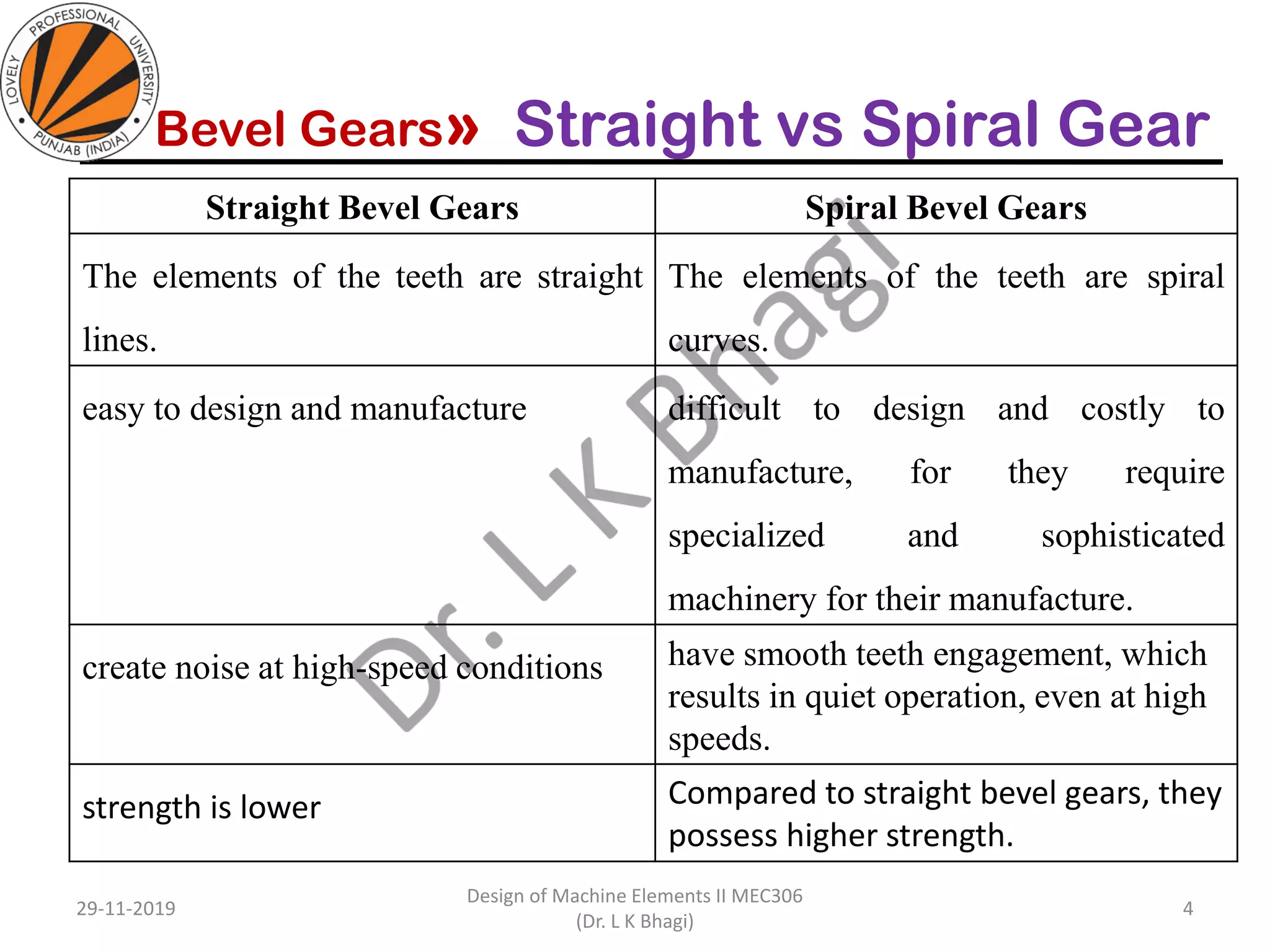
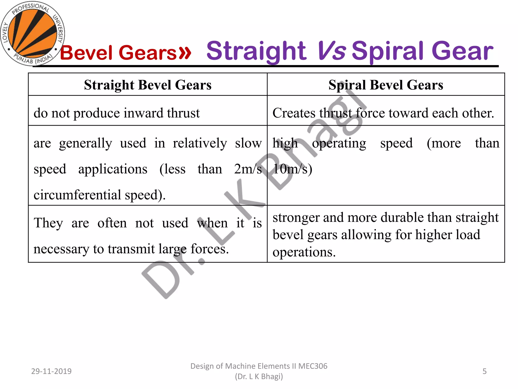
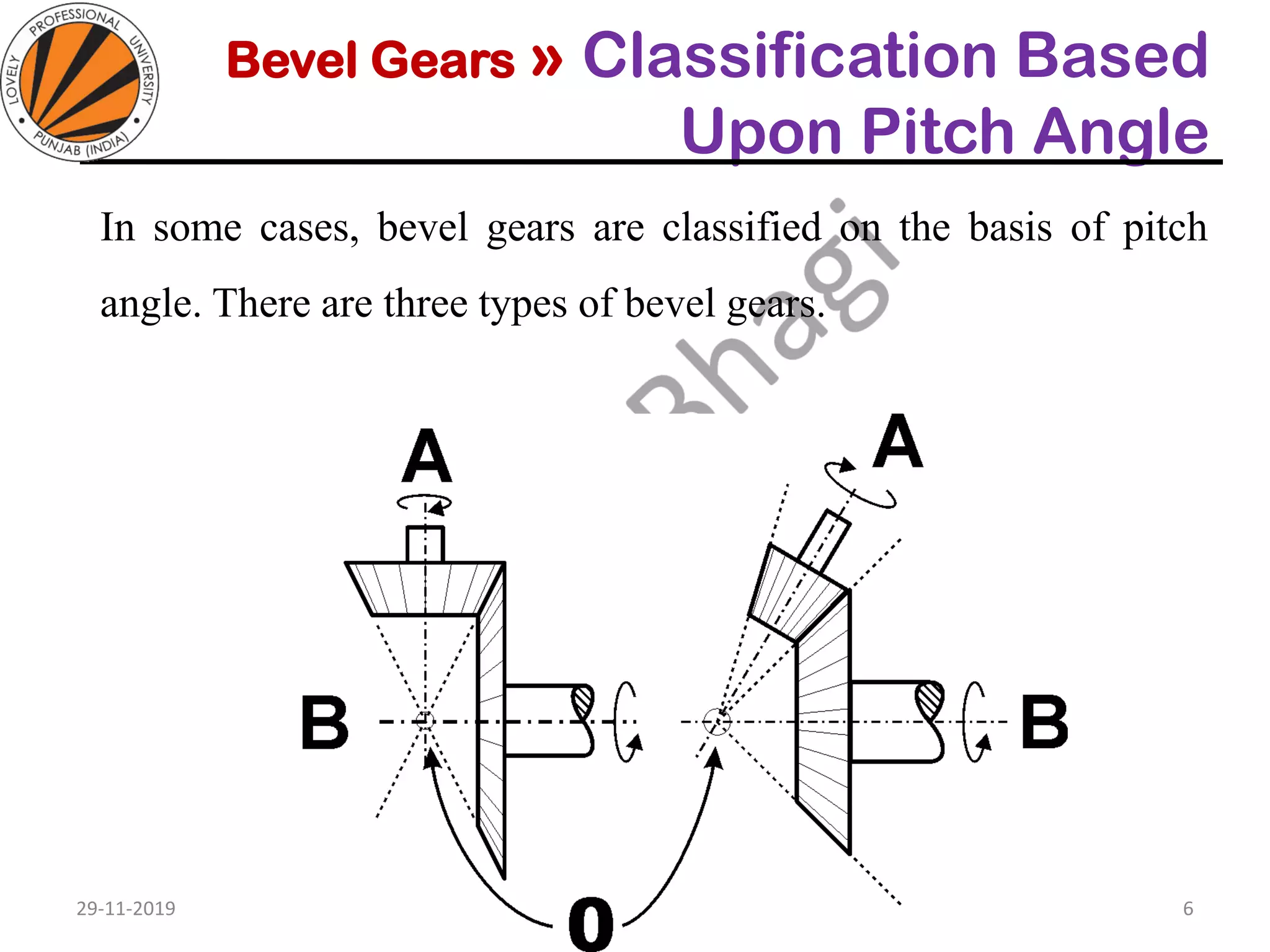
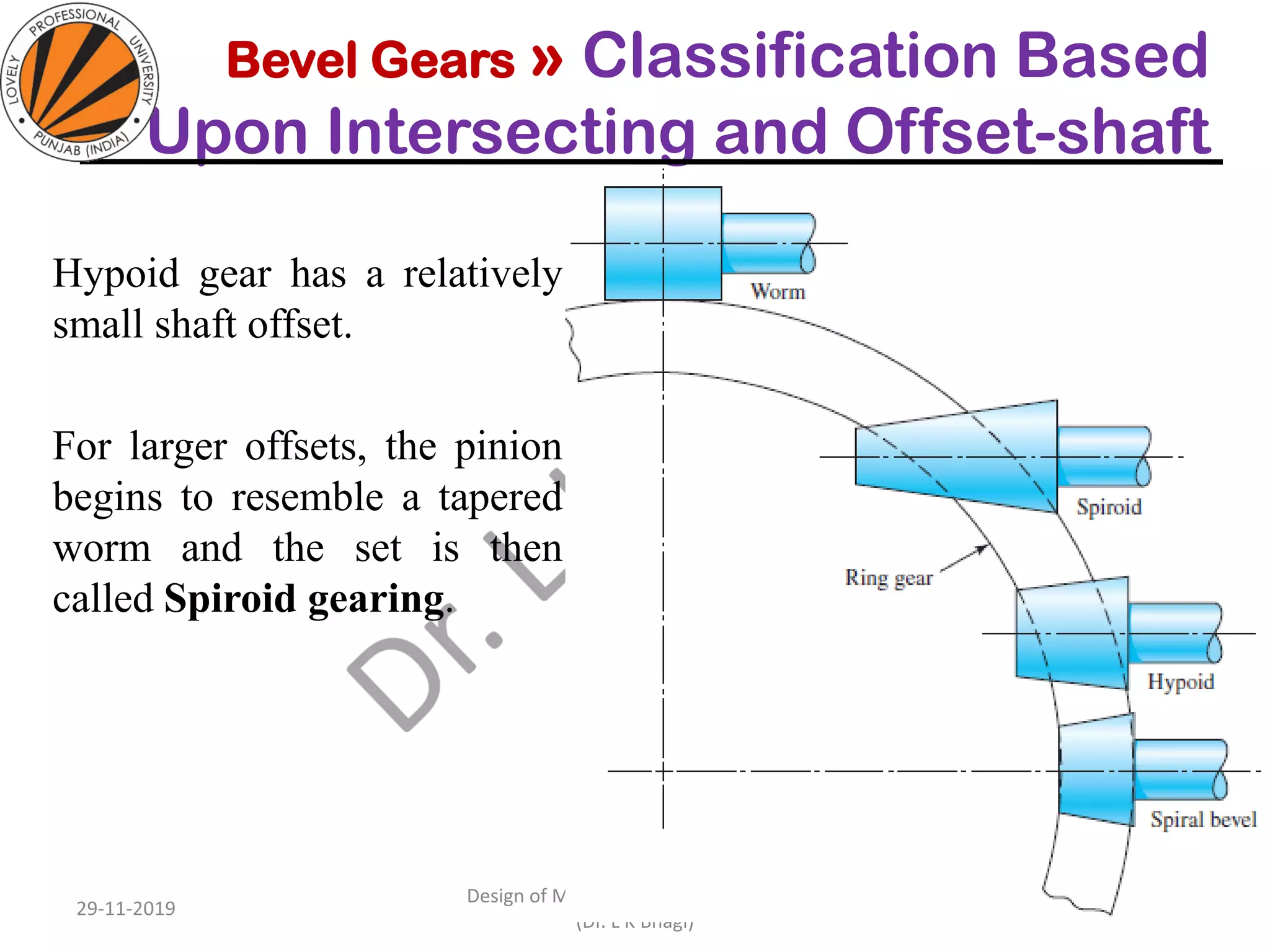
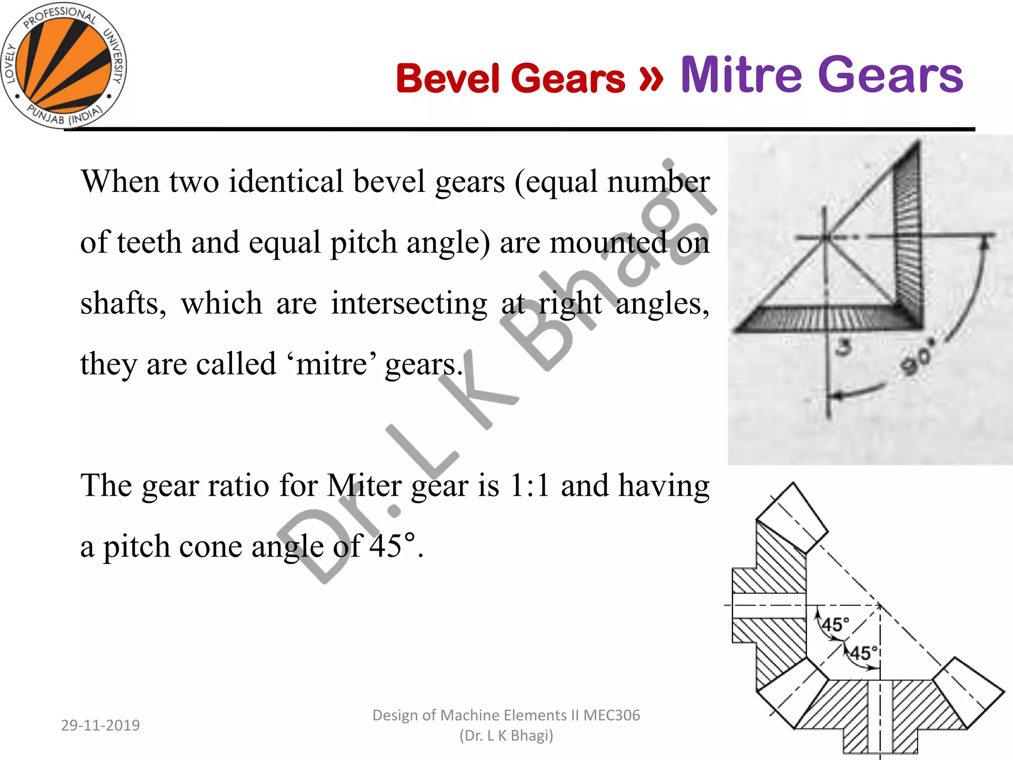
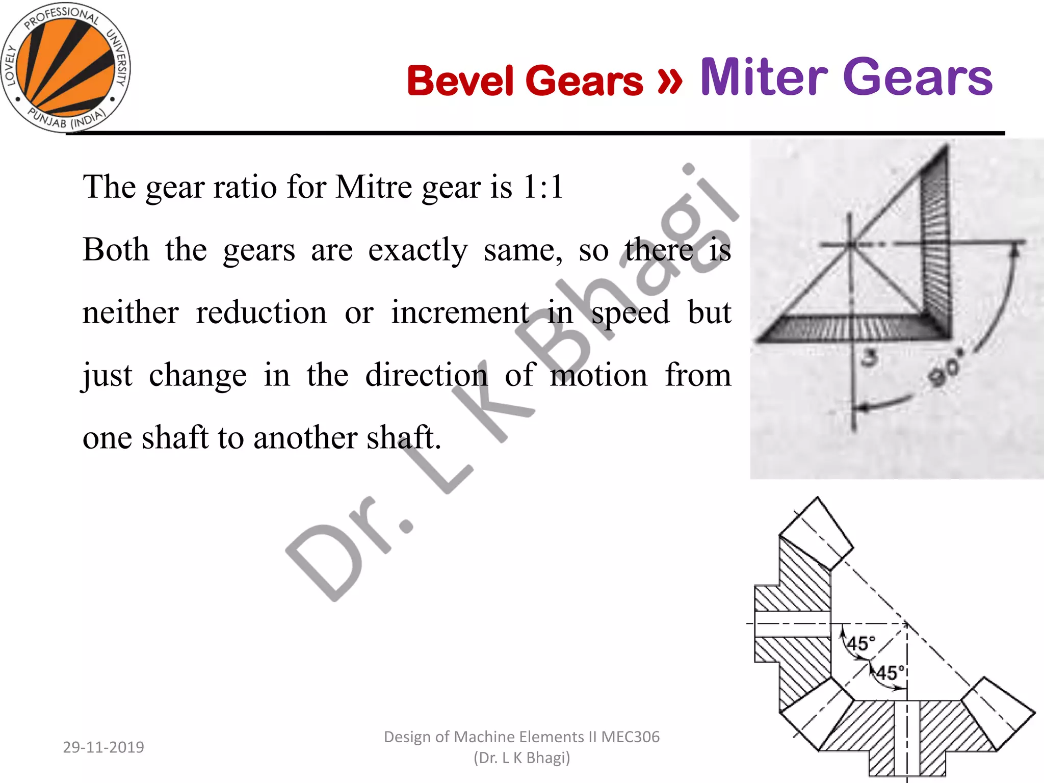
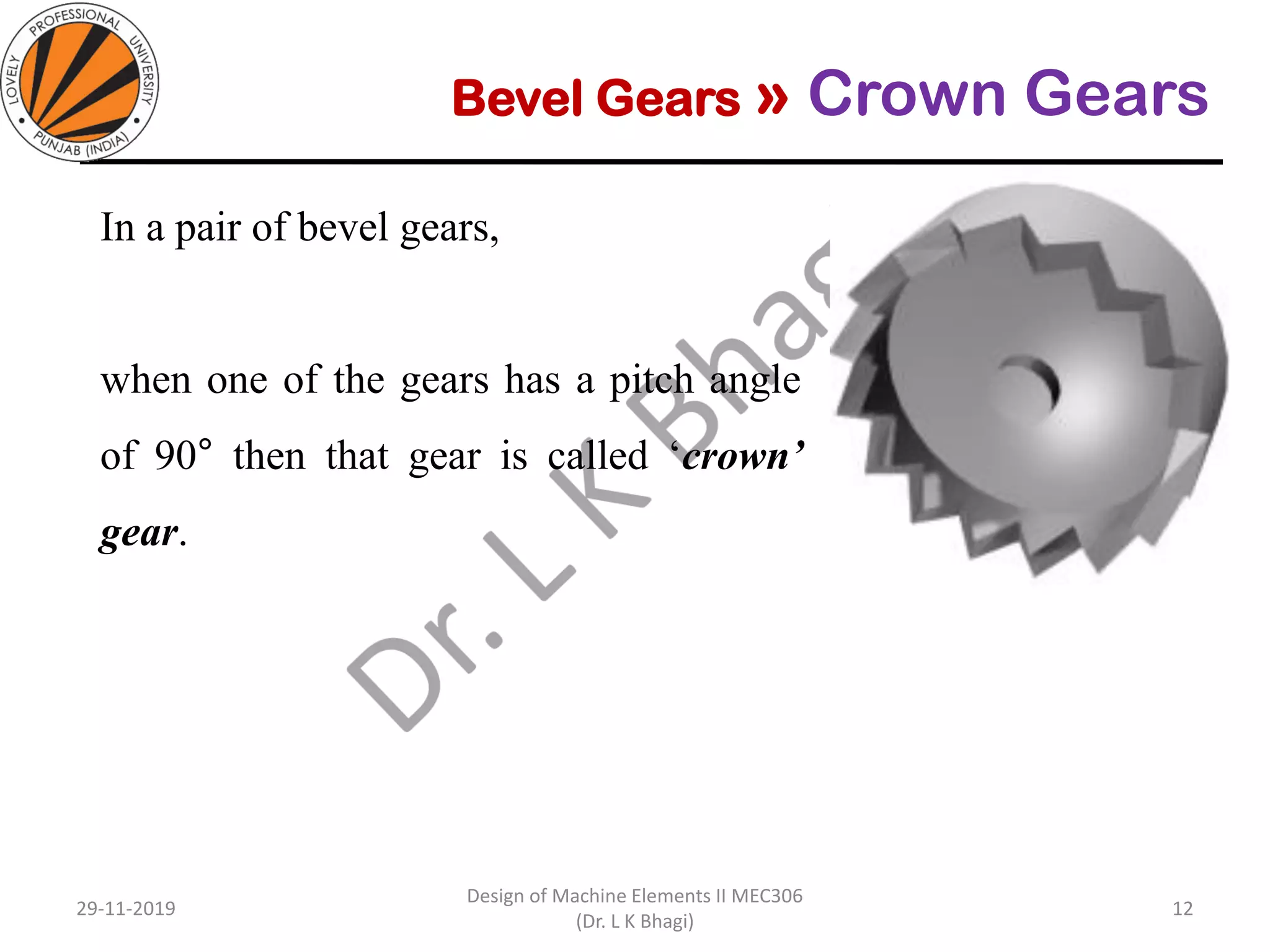
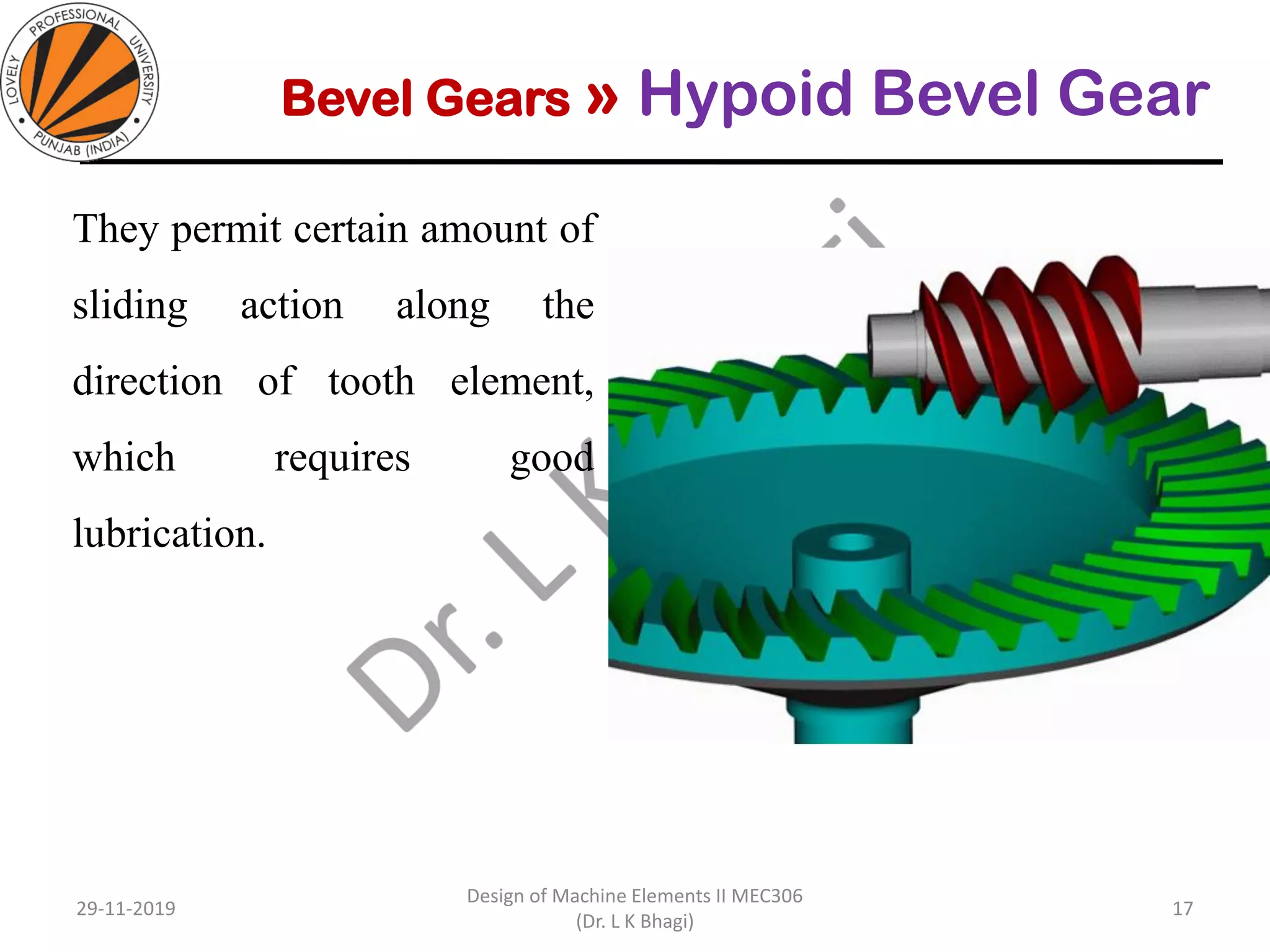
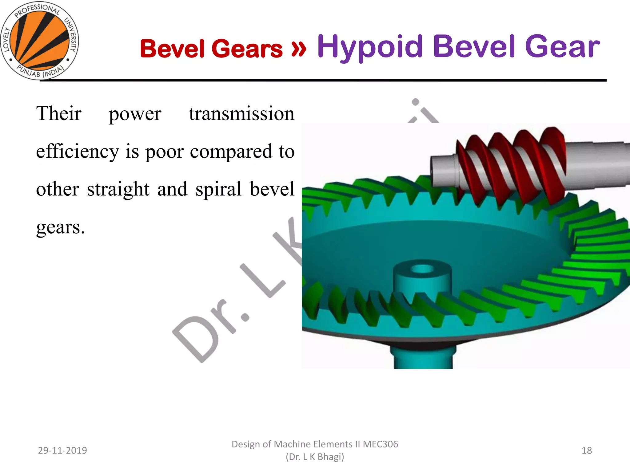
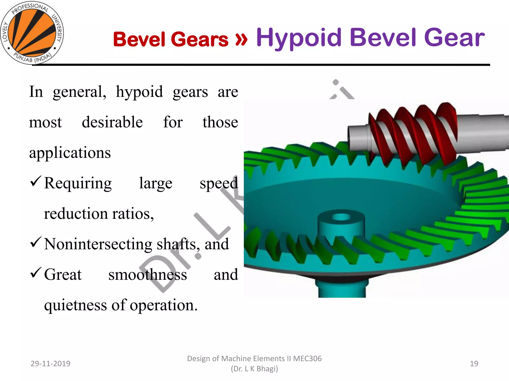
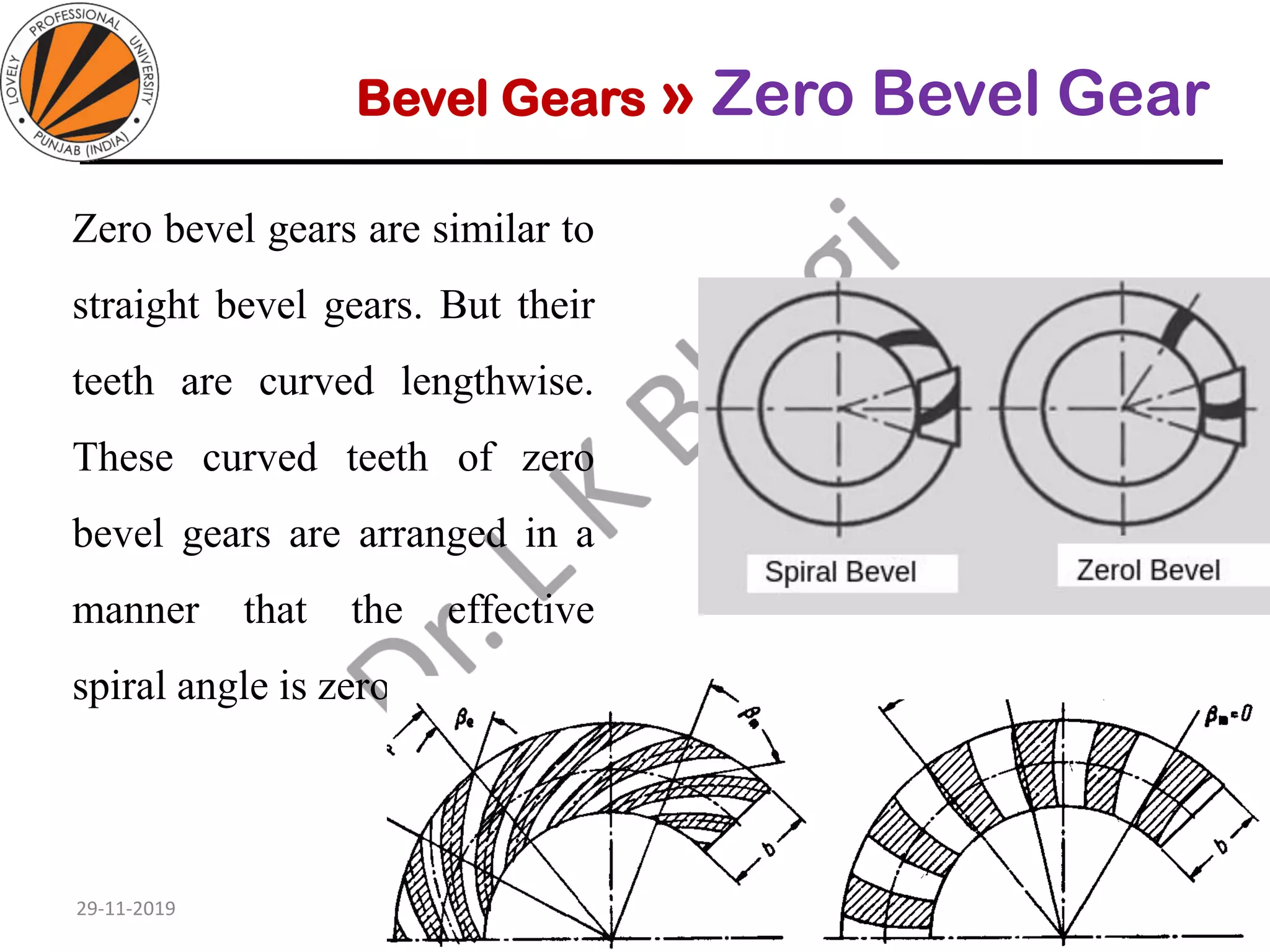
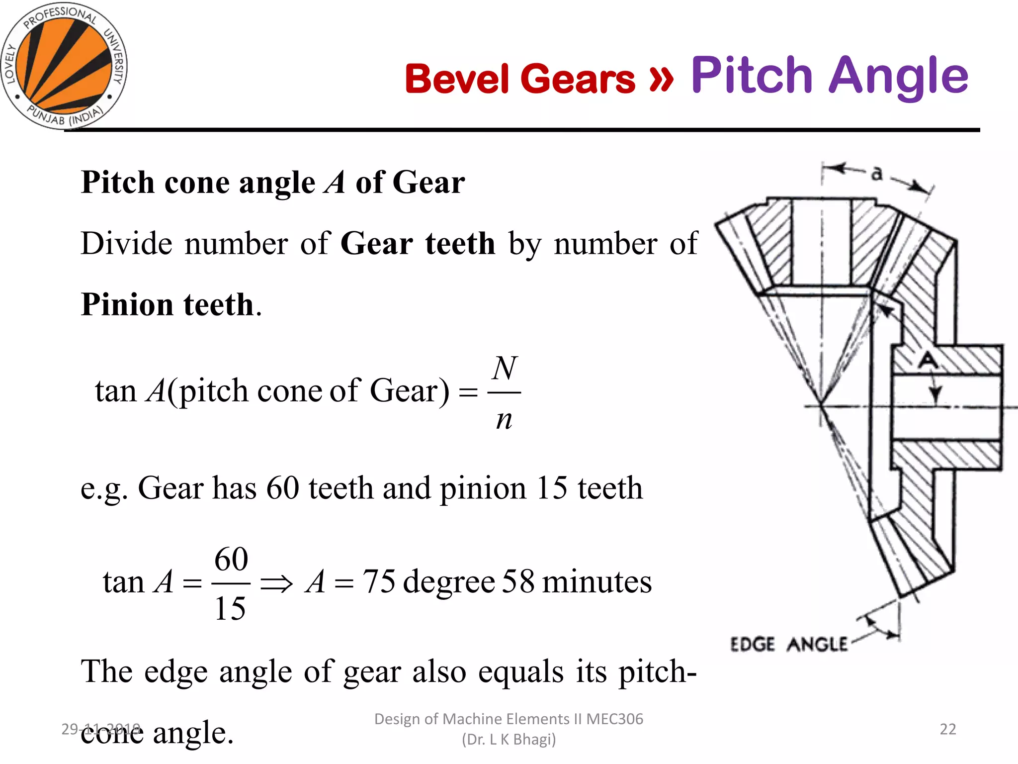
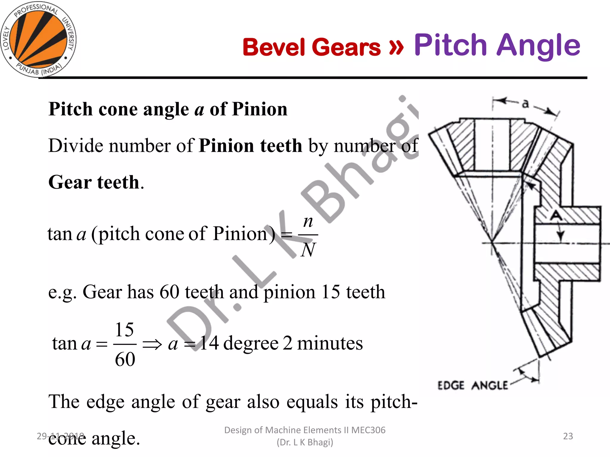
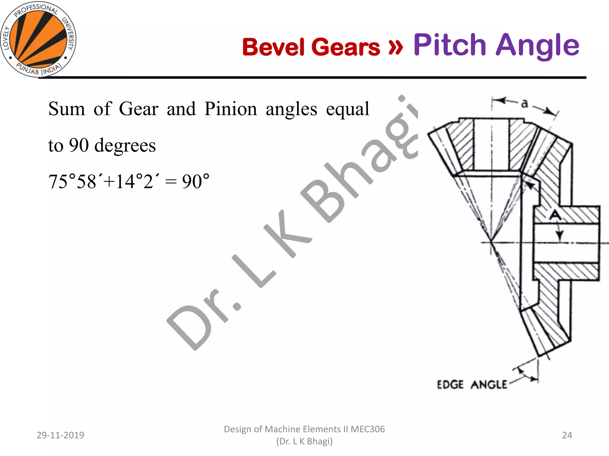


Bevel gears are a type of spur gear that mesh at a 90° angle, used to transmit power between intersecting shafts. They come in two main types: straight and spiral, with various classifications based on pitch angle and shaft orientation. The document discusses their characteristics, uses, and manufacturing considerations, highlighting differences in performance and application requirements.


