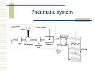
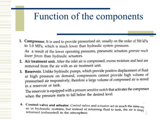
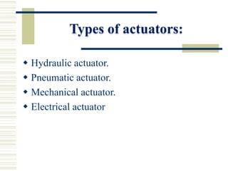
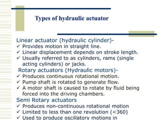
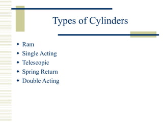
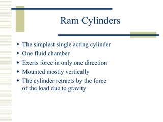
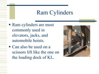
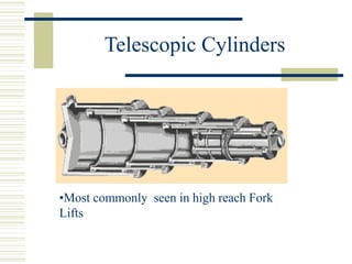
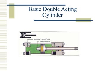
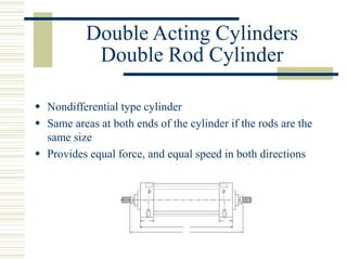
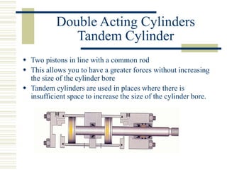
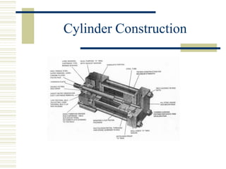
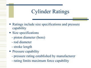
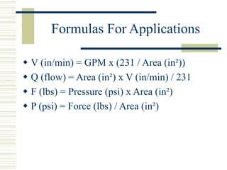
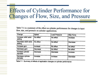
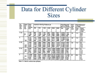
SlideShare a Scribd company logo
Overview
 Types of Cylinders
 Construction and Operation
 Cylinder Ratings
 Formulas for Application
 Cylinder Features
 Installation and Trouble Shooting
1. Hydraulic pump unit : in an actual hydraulic system a pump converts
mechanical power into fluid power.
2. Control valve : the flow of pressurized liquid discharge by the pump is
controlled by valves.
 Pressure control valves- control the liquid pressure .
 Flow control valves : control the liquid flow rate.
 Directional control valve : control the direction of flow of the liquid.
3. Hydraulic motor/cylinder
 The liquid discharged by the pump is directed to hydraulic motors or cylinders
by control valves.
 Motors are used where rotory motion is desired and cylinders are used where
linear motion is necessary.
Hydraulic system
Hydraulic systems are used to control & transmit power.
•A pump driven by prime mover (electric motor) creates flow of fluid
Basic layout of hydraulic
system
Function of components
1. The hydraulic actuator is a device used to convert the fluid power
into mechanical power to do useful work. The actuator may be of the
linear type (e.g., hydraulic cylinder) or rotary type(e.g., hydraulic motor) to
provide linear or rotary motion, respectively.
2. The hydraulic pump is used to force the fluid from the reservoir to
rest of the hydraulic circuit by converting mechanical energy into hydraulic
energy.
3. Valves are used to control the direction, pressure and flow rate of a
fluid flowing through the circuit.
4. External power supply (motor) is required to drive the pump.
5. Reservoir is used to hold the hydraulic liquid, usually hydraulic oil.
Con.
6. Piping system carries the hydraulic oil from one place to
another.
7. Filters are used to remove any foreign particles so as keep the
fluid system clean and efficient, as well as avoid damage to the
actuator and valves.
8. Pressure regulator regulates (i.e., maintains) the required
level of pressure in the hydraulic fluid.
Pneumatics
 Uses pressurized air to transmit and control power. Air is used as
the fluid because:-
 It is safe.
 It is less expensive and readily available
 It can be inducted and exhausted directly to the atmosphere and
return line is not necessary as with hydraulics.
Pneumatic system
Function of the components
Actuators
What is an actuator?
 Actuators are devices used to produce action or motion.
 Input(mainly electrical signal , air, fluids)
 Electrical signal can be low power or high power.
 Actuators output can be position or rate i.e. linear
displacement or velocity.
 Actuation can be from few microns to few meters
Actuator functional diagram
A
Power
amplification
& modulation
Energy
conversion
Control
signal
Actuator
Output
Unmodulate
Energy
source
Types of actuators:
 Hydraulic actuator.
 Pneumatic actuator.
 Mechanical actuator.
 Electrical actuator
Hydraulic actuator.
 The hydraulic actuator is a device used to convert the
fluid power into mechanical power to do useful work. The
actuator may be of the linear type (e.g., hydraulic cylinder)
or rotary type(e.g., hydraulic motor) to provide linear or
rotary motion, respectively
Linear actuator (hydraulic cylinder)-
 Provides motion in straight line.
 Linear displacement depends on stroke length.
 Usually referred to as cylinders, rams (single
acting cylinders) or jacks.
Rotary actuators (Hydraulic motors)-
 Produces continuous rotational motion.
 Pump shaft is rotated to generate flow.
 A motor shaft is caused to rotate by fluid being
forced into the driving chambers.
Semi Rotary actuators
 Produces non-continuous rotational motion
 Limited to less than one revolution (<360)
 Used to produce oscillatory motions in
Types of Cylinders
 Ram
 Single Acting
 Telescopic
 Spring Return
 Double Acting
Ram Cylinders
 The simplest single acting cylinder
 One fluid chamber
 Exerts force in only one direction
 Mounted mostly vertically
 The cylinder retracts by the force
of the load due to gravity
Ram Cylinders
 Ram cylinders are most
commonly used in
elevators, jacks, and
automobile hoists.
 Can also be used on a
scissors lift like the one on
the loading dock of KL.
Single Acting Cylinders
 Acts much like a ram cylinder
 Main difference is that the single acting
cylinder uses a piston. The leakage flow that
goes past the piston is ported the tank.
Telescopic Cylinders
 Mostly a single acting cylinder
 Series of rod segments called sleeves, most
common to only have 4 or 5 sleeves in each
cylinder
 The sleeves work together to provide a longer
stroke
 The maximum force is at the collapsed position
 The speed will increase at each stage, but will not
allow as much force.
Telescopic Cylinders
•Most commonly seen in high reach Fork
Lifts
Spring Return Cylinders
 Considered a single acting cylinder
 Pressure applied to the cap end pushes the spring down as
the rod is extending
 When the pressure is removed the spring force allows the
cylinder to retract
 The drain is in the spring chamber and allows the leakage
flow past the piston seal
Double Acting Cylinders
Types
 Basic double acting (differential
cylinder)
 Double rod cylinder (nondifferential
cylinder)
 Tandem cylinder
Double Acting Cylinders
 Most common type of cylinder
 Pressure is applied to both rod end and
cap end
 The majority of the cylinders are basic.
This means that there is unequal areas at
either end.
Double Acting Cylinders
 Rod extension is slower because has a larger
area, but allows a greater force because of
the bigger area.
 Retract is faster because of the smaller area,
but the force allowed is smaller because of
the smaller area.
Basic Double Acting
Cylinder
Double Acting Cylinders
Double Rod Cylinder
 Nondifferential type cylinder
 Same areas at both ends of the cylinder if the rods are the
same size
 Provides equal force, and equal speed in both directions
Double Acting Cylinders
Tandem Cylinder
 Two pistons in line with a common rod
 This allows you to have a greater forces without increasing
the size of the cylinder bore
 Tandem cylinders are used in places where there is
insufficient space to increase the size of the cylinder bore.
Cylinder Construction
Cylinder Actuation
 Fluid routed to and from cylinder through
ports in each of the heads
 Cylinder retracts from pressure to rod end
port and the other port connected to tank
 Cylinder extends from pressure to cap end
port and rod end port connected to tank
Cylinder Mounting
 Main function to anchor the cylinder
 Mounting methods include tie rod, bolt
mount, flange, trunnion, side lug and side
tapped, and clevis
 Tie rod is most common
Cylinder Mounting
Cylinder Mounting
Cylinder Ratings
 Ratings include size specifications and pressure
capability
 Size specifications
- piston diameter (bore)
- rod diameter
- stroke length
 Pressure capability
- pressure rating established by manufacturer
- rating limits maximum force capability
Formulas For Applications
 V (in/min) = GPM x (231 / Area (in²))
 Q (flow) = Area (in²) x V (in/min) / 231
 F (lbs) = Pressure (psi) x Area (in²)
 P (psi) = Force (lbs) / Area (in²)
Effects of Cylinder Performance for
Changes of Flow, Size, and Pressure
Data for Different Cylinder
Sizes
Cylinder Features
 Basic size and pressure ratings are not the only things that define a
cylinder
 Features such as:
- seals
- cushions
- stop tubes
- rod spacers
- ports
- bleed ports
-limit switches
Seals
 Cast iron is most common piston seal
 Long service life is most important characteristic
 Rubber-like materials are the most common rod seal
 Rod wiper or scraper keeps foreign material from entering
the cylinder and the hydraulic system
Cylinder Cushions
 Used to slow down the piston at the end of its
stroke
 Basic elements include the plunger,
adjustable cushion orifice, and a check valve
Stop Tubes
 Metal collar that fits over piston rod next to piston
 Used primarily on long stroke cylinders
 Provides better cylinder rod support
 Majority of applications do not require a stop tube
Tie Rod Spacers
 Tie rod spacers and center supports improve rigidity of long
stroke tie rod cylinders
 Spacer keeps proper position and prevents excessive deflection
 Tie rod center support has side mounting lugs and serves as
additional mounting location
Ports
 Internal or external opening in a cylinder or a valve
 Designed to allow the passing of fluid into or out of
the component
 Wide variety of port type configurations
 Straight thread O-ring fittings are highly
recommended for leak-free connections
 Poor installation of tubing or hose to port causes
leakage
Bleed Ports
 Usually cylinders bleed air when ports are
vertical on top
 Bleed ports are necessary to remove trapped
air when the ports are installed on the bottom
of the cylinder
 Desirable on high speed, high performance,
heavy load applications
Limit Switches
 Signal rod position to a control circuit or a safety circuit to limit end of
travel
 Common types
-mechanical = mechanical actuation of electrical switch when switch is
activated by lead angle on a hardened cylinder cushion
- proximity = activated when metal cushion passes close to magnetic
pickup of the switch
* becoming increasingly popular due to simplicity
Cylinder Installation and
Troubleshooting
 Cylinder application design » hydraulic
engineers
 Installation » hydraulic technician
 Proper installation and maintenance is crucial
to all components to achieve max efficiency
 Recognizing and controlling potential
problems is purpose of troubleshooting
Design Problem
A dump truck to lift 5 ton. Specify a cylinder.
Velocity in retract is 15 in/sec
Stroke = 18 in
P = 2000 psi
References
 Eaton-Vickers Text, Industrial Hydraulics
Manual 4th Edition 2001
 www.parker.com
 www.airlinehyd.com
 www.caterpillar.com
 www.duramastercylinders.com

More Related Content

Similar to chapterfive [Autosaved].ppt

lecture-1.ppt
lecture-1.pptlecture-1.ppt
lecture-1.ppt
StAnnesCETMECHDepart
 
lecture-1.ppt
lecture-1.pptlecture-1.ppt
lecture-1.ppt
ChandreshTripathi6
 
Pumps presentation
Pumps presentationPumps presentation
Pumps presentation
arifsanghi786
 
Ce.pptx 2
Ce.pptx 2Ce.pptx 2
Ce.pptx 2
Hrdbs
 
Presentation on pneumatic actuator
Presentation on pneumatic actuatorPresentation on pneumatic actuator
Presentation on pneumatic actuator
Manish Tiwari
 
Babic components of hydraulic & pneumatic systems
Babic components of hydraulic & pneumatic systemsBabic components of hydraulic & pneumatic systems
Babic components of hydraulic & pneumatic systemswakurets_21
 
Centrifugal Pumps and Compressor.pdf [Autosaved].pptx
Centrifugal Pumps and Compressor.pdf [Autosaved].pptxCentrifugal Pumps and Compressor.pdf [Autosaved].pptx
Centrifugal Pumps and Compressor.pdf [Autosaved].pptx
FahadReda2
 
Basic pneumatics
Basic pneumaticsBasic pneumatics
Basic pneumatics
RutwikBonde
 
Introduction to Pneumatic Systems
Introduction to Pneumatic SystemsIntroduction to Pneumatic Systems
Introduction to Pneumatic Systems
RAHUL THAKER
 
UNIT 2 PPT
UNIT 2 PPTUNIT 2 PPT
UNIT 2 PPT
gopalkrishnan202
 
Unit 2=actuators &amp; cylinders
Unit 2=actuators &amp; cylindersUnit 2=actuators &amp; cylinders
Unit 2=actuators &amp; cylinders
KawinKit
 
Unit 2=actuators &amp; cylinders
Unit 2=actuators &amp; cylindersUnit 2=actuators &amp; cylinders
Unit 2=actuators &amp; cylinders
Karthik R
 
Week 4 pe 3231 pump cyl mot tank accu sho abs rev oct 16 final
Week 4 pe 3231 pump cyl mot tank accu sho abs rev oct 16  finalWeek 4 pe 3231 pump cyl mot tank accu sho abs rev oct 16  final
Week 4 pe 3231 pump cyl mot tank accu sho abs rev oct 16 final
Charlton Inao
 
1 hydraulic actuators cylinders
1 hydraulic actuators cylinders1 hydraulic actuators cylinders
1 hydraulic actuators cylinders
Dr.R. SELVAM
 
Actuators in hydraulic system
Actuators in hydraulic systemActuators in hydraulic system
Actuators in hydraulic system
Ashish Kamble
 
ROBOT DRIVE SYSTEMS AND END EFFECTORS
ROBOT DRIVE SYSTEMS AND END EFFECTORSROBOT DRIVE SYSTEMS AND END EFFECTORS
ROBOT DRIVE SYSTEMS AND END EFFECTORS
TAMILMECHKIT
 
DOC-20240201-WA0004..pdf
DOC-20240201-WA0004..pdfDOC-20240201-WA0004..pdf
DOC-20240201-WA0004..pdf
AbhayKumar653638
 
2014916 635220964350095000
2014916 6352209643500950002014916 635220964350095000
2014916 635220964350095000Bheemesh Gudelli
 
Prof.n.nagraj pneumatic control
Prof.n.nagraj pneumatic controlProf.n.nagraj pneumatic control
Prof.n.nagraj pneumatic control
Praveen Djadhav
 
Basics of hydraulices
Basics of hydraulicesBasics of hydraulices
Basics of hydraulices
RICHARDTENZINGP21ME
 

Similar to chapterfive [Autosaved].ppt (20)

lecture-1.ppt
lecture-1.pptlecture-1.ppt
lecture-1.ppt
 
lecture-1.ppt
lecture-1.pptlecture-1.ppt
lecture-1.ppt
 
Pumps presentation
Pumps presentationPumps presentation
Pumps presentation
 
Ce.pptx 2
Ce.pptx 2Ce.pptx 2
Ce.pptx 2
 
Presentation on pneumatic actuator
Presentation on pneumatic actuatorPresentation on pneumatic actuator
Presentation on pneumatic actuator
 
Babic components of hydraulic & pneumatic systems
Babic components of hydraulic & pneumatic systemsBabic components of hydraulic & pneumatic systems
Babic components of hydraulic & pneumatic systems
 
Centrifugal Pumps and Compressor.pdf [Autosaved].pptx
Centrifugal Pumps and Compressor.pdf [Autosaved].pptxCentrifugal Pumps and Compressor.pdf [Autosaved].pptx
Centrifugal Pumps and Compressor.pdf [Autosaved].pptx
 
Basic pneumatics
Basic pneumaticsBasic pneumatics
Basic pneumatics
 
Introduction to Pneumatic Systems
Introduction to Pneumatic SystemsIntroduction to Pneumatic Systems
Introduction to Pneumatic Systems
 
UNIT 2 PPT
UNIT 2 PPTUNIT 2 PPT
UNIT 2 PPT
 
Unit 2=actuators &amp; cylinders
Unit 2=actuators &amp; cylindersUnit 2=actuators &amp; cylinders
Unit 2=actuators &amp; cylinders
 
Unit 2=actuators &amp; cylinders
Unit 2=actuators &amp; cylindersUnit 2=actuators &amp; cylinders
Unit 2=actuators &amp; cylinders
 
Week 4 pe 3231 pump cyl mot tank accu sho abs rev oct 16 final
Week 4 pe 3231 pump cyl mot tank accu sho abs rev oct 16  finalWeek 4 pe 3231 pump cyl mot tank accu sho abs rev oct 16  final
Week 4 pe 3231 pump cyl mot tank accu sho abs rev oct 16 final
 
1 hydraulic actuators cylinders
1 hydraulic actuators cylinders1 hydraulic actuators cylinders
1 hydraulic actuators cylinders
 
Actuators in hydraulic system
Actuators in hydraulic systemActuators in hydraulic system
Actuators in hydraulic system
 
ROBOT DRIVE SYSTEMS AND END EFFECTORS
ROBOT DRIVE SYSTEMS AND END EFFECTORSROBOT DRIVE SYSTEMS AND END EFFECTORS
ROBOT DRIVE SYSTEMS AND END EFFECTORS
 
DOC-20240201-WA0004..pdf
DOC-20240201-WA0004..pdfDOC-20240201-WA0004..pdf
DOC-20240201-WA0004..pdf
 
2014916 635220964350095000
2014916 6352209643500950002014916 635220964350095000
2014916 635220964350095000
 
Prof.n.nagraj pneumatic control
Prof.n.nagraj pneumatic controlProf.n.nagraj pneumatic control
Prof.n.nagraj pneumatic control
 
Basics of hydraulices
Basics of hydraulicesBasics of hydraulices
Basics of hydraulices
 

Recently uploaded

Architectural Portfolio Sean Lockwood
Architectural Portfolio Sean LockwoodArchitectural Portfolio Sean Lockwood
Architectural Portfolio Sean Lockwood
seandesed
 
Halogenation process of chemical process industries
Halogenation process of chemical process industriesHalogenation process of chemical process industries
Halogenation process of chemical process industries
MuhammadTufail242431
 
Top 10 Oil and Gas Projects in Saudi Arabia 2024.pdf
Top 10 Oil and Gas Projects in Saudi Arabia 2024.pdfTop 10 Oil and Gas Projects in Saudi Arabia 2024.pdf
Top 10 Oil and Gas Projects in Saudi Arabia 2024.pdf
Teleport Manpower Consultant
 
LIGA(E)11111111111111111111111111111111111111111.ppt
LIGA(E)11111111111111111111111111111111111111111.pptLIGA(E)11111111111111111111111111111111111111111.ppt
LIGA(E)11111111111111111111111111111111111111111.ppt
ssuser9bd3ba
 
Student information management system project report ii.pdf
Student information management system project report ii.pdfStudent information management system project report ii.pdf
Student information management system project report ii.pdf
Kamal Acharya
 
在线办理(ANU毕业证书)澳洲国立大学毕业证录取通知书一模一样
在线办理(ANU毕业证书)澳洲国立大学毕业证录取通知书一模一样在线办理(ANU毕业证书)澳洲国立大学毕业证录取通知书一模一样
在线办理(ANU毕业证书)澳洲国立大学毕业证录取通知书一模一样
obonagu
 
ASME IX(9) 2007 Full Version .pdf
ASME IX(9)  2007 Full Version       .pdfASME IX(9)  2007 Full Version       .pdf
ASME IX(9) 2007 Full Version .pdf
AhmedHussein950959
 
Sachpazis:Terzaghi Bearing Capacity Estimation in simple terms with Calculati...
Sachpazis:Terzaghi Bearing Capacity Estimation in simple terms with Calculati...Sachpazis:Terzaghi Bearing Capacity Estimation in simple terms with Calculati...
Sachpazis:Terzaghi Bearing Capacity Estimation in simple terms with Calculati...
Dr.Costas Sachpazis
 
Final project report on grocery store management system..pdf
Final project report on grocery store management system..pdfFinal project report on grocery store management system..pdf
Final project report on grocery store management system..pdf
Kamal Acharya
 
ethical hacking-mobile hacking methods.ppt
ethical hacking-mobile hacking methods.pptethical hacking-mobile hacking methods.ppt
ethical hacking-mobile hacking methods.ppt
Jayaprasanna4
 
Gen AI Study Jams _ For the GDSC Leads in India.pdf
Gen AI Study Jams _ For the GDSC Leads in India.pdfGen AI Study Jams _ For the GDSC Leads in India.pdf
Gen AI Study Jams _ For the GDSC Leads in India.pdf
gdsczhcet
 
Industrial Training at Shahjalal Fertilizer Company Limited (SFCL)
Industrial Training at Shahjalal Fertilizer Company Limited (SFCL)Industrial Training at Shahjalal Fertilizer Company Limited (SFCL)
Industrial Training at Shahjalal Fertilizer Company Limited (SFCL)
MdTanvirMahtab2
 
AKS UNIVERSITY Satna Final Year Project By OM Hardaha.pdf
AKS UNIVERSITY Satna Final Year Project By OM Hardaha.pdfAKS UNIVERSITY Satna Final Year Project By OM Hardaha.pdf
AKS UNIVERSITY Satna Final Year Project By OM Hardaha.pdf
SamSarthak3
 
weather web application report.pdf
weather web application report.pdfweather web application report.pdf
weather web application report.pdf
Pratik Pawar
 
Design and Analysis of Algorithms-DP,Backtracking,Graphs,B&B
Design and Analysis of Algorithms-DP,Backtracking,Graphs,B&BDesign and Analysis of Algorithms-DP,Backtracking,Graphs,B&B
Design and Analysis of Algorithms-DP,Backtracking,Graphs,B&B
Sreedhar Chowdam
 
Courier management system project report.pdf
Courier management system project report.pdfCourier management system project report.pdf
Courier management system project report.pdf
Kamal Acharya
 
ethical hacking in wireless-hacking1.ppt
ethical hacking in wireless-hacking1.pptethical hacking in wireless-hacking1.ppt
ethical hacking in wireless-hacking1.ppt
Jayaprasanna4
 
HYDROPOWER - Hydroelectric power generation
HYDROPOWER - Hydroelectric power generationHYDROPOWER - Hydroelectric power generation
HYDROPOWER - Hydroelectric power generation
Robbie Edward Sayers
 
NO1 Uk best vashikaran specialist in delhi vashikaran baba near me online vas...
NO1 Uk best vashikaran specialist in delhi vashikaran baba near me online vas...NO1 Uk best vashikaran specialist in delhi vashikaran baba near me online vas...
NO1 Uk best vashikaran specialist in delhi vashikaran baba near me online vas...
Amil Baba Dawood bangali
 
Automobile Management System Project Report.pdf
Automobile Management System Project Report.pdfAutomobile Management System Project Report.pdf
Automobile Management System Project Report.pdf
Kamal Acharya
 

Recently uploaded (20)

Architectural Portfolio Sean Lockwood
Architectural Portfolio Sean LockwoodArchitectural Portfolio Sean Lockwood
Architectural Portfolio Sean Lockwood
 
Halogenation process of chemical process industries
Halogenation process of chemical process industriesHalogenation process of chemical process industries
Halogenation process of chemical process industries
 
Top 10 Oil and Gas Projects in Saudi Arabia 2024.pdf
Top 10 Oil and Gas Projects in Saudi Arabia 2024.pdfTop 10 Oil and Gas Projects in Saudi Arabia 2024.pdf
Top 10 Oil and Gas Projects in Saudi Arabia 2024.pdf
 
LIGA(E)11111111111111111111111111111111111111111.ppt
LIGA(E)11111111111111111111111111111111111111111.pptLIGA(E)11111111111111111111111111111111111111111.ppt
LIGA(E)11111111111111111111111111111111111111111.ppt
 
Student information management system project report ii.pdf
Student information management system project report ii.pdfStudent information management system project report ii.pdf
Student information management system project report ii.pdf
 
在线办理(ANU毕业证书)澳洲国立大学毕业证录取通知书一模一样
在线办理(ANU毕业证书)澳洲国立大学毕业证录取通知书一模一样在线办理(ANU毕业证书)澳洲国立大学毕业证录取通知书一模一样
在线办理(ANU毕业证书)澳洲国立大学毕业证录取通知书一模一样
 
ASME IX(9) 2007 Full Version .pdf
ASME IX(9)  2007 Full Version       .pdfASME IX(9)  2007 Full Version       .pdf
ASME IX(9) 2007 Full Version .pdf
 
Sachpazis:Terzaghi Bearing Capacity Estimation in simple terms with Calculati...
Sachpazis:Terzaghi Bearing Capacity Estimation in simple terms with Calculati...Sachpazis:Terzaghi Bearing Capacity Estimation in simple terms with Calculati...
Sachpazis:Terzaghi Bearing Capacity Estimation in simple terms with Calculati...
 
Final project report on grocery store management system..pdf
Final project report on grocery store management system..pdfFinal project report on grocery store management system..pdf
Final project report on grocery store management system..pdf
 
ethical hacking-mobile hacking methods.ppt
ethical hacking-mobile hacking methods.pptethical hacking-mobile hacking methods.ppt
ethical hacking-mobile hacking methods.ppt
 
Gen AI Study Jams _ For the GDSC Leads in India.pdf
Gen AI Study Jams _ For the GDSC Leads in India.pdfGen AI Study Jams _ For the GDSC Leads in India.pdf
Gen AI Study Jams _ For the GDSC Leads in India.pdf
 
Industrial Training at Shahjalal Fertilizer Company Limited (SFCL)
Industrial Training at Shahjalal Fertilizer Company Limited (SFCL)Industrial Training at Shahjalal Fertilizer Company Limited (SFCL)
Industrial Training at Shahjalal Fertilizer Company Limited (SFCL)
 
AKS UNIVERSITY Satna Final Year Project By OM Hardaha.pdf
AKS UNIVERSITY Satna Final Year Project By OM Hardaha.pdfAKS UNIVERSITY Satna Final Year Project By OM Hardaha.pdf
AKS UNIVERSITY Satna Final Year Project By OM Hardaha.pdf
 
weather web application report.pdf
weather web application report.pdfweather web application report.pdf
weather web application report.pdf
 
Design and Analysis of Algorithms-DP,Backtracking,Graphs,B&B
Design and Analysis of Algorithms-DP,Backtracking,Graphs,B&BDesign and Analysis of Algorithms-DP,Backtracking,Graphs,B&B
Design and Analysis of Algorithms-DP,Backtracking,Graphs,B&B
 
Courier management system project report.pdf
Courier management system project report.pdfCourier management system project report.pdf
Courier management system project report.pdf
 
ethical hacking in wireless-hacking1.ppt
ethical hacking in wireless-hacking1.pptethical hacking in wireless-hacking1.ppt
ethical hacking in wireless-hacking1.ppt
 
HYDROPOWER - Hydroelectric power generation
HYDROPOWER - Hydroelectric power generationHYDROPOWER - Hydroelectric power generation
HYDROPOWER - Hydroelectric power generation
 
NO1 Uk best vashikaran specialist in delhi vashikaran baba near me online vas...
NO1 Uk best vashikaran specialist in delhi vashikaran baba near me online vas...NO1 Uk best vashikaran specialist in delhi vashikaran baba near me online vas...
NO1 Uk best vashikaran specialist in delhi vashikaran baba near me online vas...
 
Automobile Management System Project Report.pdf
Automobile Management System Project Report.pdfAutomobile Management System Project Report.pdf
Automobile Management System Project Report.pdf
 

chapterfive [Autosaved].ppt

  • 1. Overview  Types of Cylinders  Construction and Operation  Cylinder Ratings  Formulas for Application  Cylinder Features  Installation and Trouble Shooting
  • 2. 1. Hydraulic pump unit : in an actual hydraulic system a pump converts mechanical power into fluid power. 2. Control valve : the flow of pressurized liquid discharge by the pump is controlled by valves.  Pressure control valves- control the liquid pressure .  Flow control valves : control the liquid flow rate.  Directional control valve : control the direction of flow of the liquid. 3. Hydraulic motor/cylinder  The liquid discharged by the pump is directed to hydraulic motors or cylinders by control valves.  Motors are used where rotory motion is desired and cylinders are used where linear motion is necessary.
  • 3. Hydraulic system Hydraulic systems are used to control & transmit power. •A pump driven by prime mover (electric motor) creates flow of fluid
  • 4. Basic layout of hydraulic system
  • 5. Function of components 1. The hydraulic actuator is a device used to convert the fluid power into mechanical power to do useful work. The actuator may be of the linear type (e.g., hydraulic cylinder) or rotary type(e.g., hydraulic motor) to provide linear or rotary motion, respectively. 2. The hydraulic pump is used to force the fluid from the reservoir to rest of the hydraulic circuit by converting mechanical energy into hydraulic energy. 3. Valves are used to control the direction, pressure and flow rate of a fluid flowing through the circuit. 4. External power supply (motor) is required to drive the pump. 5. Reservoir is used to hold the hydraulic liquid, usually hydraulic oil.
  • 6. Con. 6. Piping system carries the hydraulic oil from one place to another. 7. Filters are used to remove any foreign particles so as keep the fluid system clean and efficient, as well as avoid damage to the actuator and valves. 8. Pressure regulator regulates (i.e., maintains) the required level of pressure in the hydraulic fluid.
  • 7. Pneumatics  Uses pressurized air to transmit and control power. Air is used as the fluid because:-  It is safe.  It is less expensive and readily available  It can be inducted and exhausted directly to the atmosphere and return line is not necessary as with hydraulics.
  • 9. Function of the components
  • 10.
  • 11. Actuators What is an actuator?  Actuators are devices used to produce action or motion.  Input(mainly electrical signal , air, fluids)  Electrical signal can be low power or high power.  Actuators output can be position or rate i.e. linear displacement or velocity.  Actuation can be from few microns to few meters
  • 12. Actuator functional diagram A Power amplification & modulation Energy conversion Control signal Actuator Output Unmodulate Energy source
  • 13. Types of actuators:  Hydraulic actuator.  Pneumatic actuator.  Mechanical actuator.  Electrical actuator
  • 14. Hydraulic actuator.  The hydraulic actuator is a device used to convert the fluid power into mechanical power to do useful work. The actuator may be of the linear type (e.g., hydraulic cylinder) or rotary type(e.g., hydraulic motor) to provide linear or rotary motion, respectively
  • 15. Linear actuator (hydraulic cylinder)-  Provides motion in straight line.  Linear displacement depends on stroke length.  Usually referred to as cylinders, rams (single acting cylinders) or jacks. Rotary actuators (Hydraulic motors)-  Produces continuous rotational motion.  Pump shaft is rotated to generate flow.  A motor shaft is caused to rotate by fluid being forced into the driving chambers. Semi Rotary actuators  Produces non-continuous rotational motion  Limited to less than one revolution (<360)  Used to produce oscillatory motions in
  • 16. Types of Cylinders  Ram  Single Acting  Telescopic  Spring Return  Double Acting
  • 17. Ram Cylinders  The simplest single acting cylinder  One fluid chamber  Exerts force in only one direction  Mounted mostly vertically  The cylinder retracts by the force of the load due to gravity
  • 18. Ram Cylinders  Ram cylinders are most commonly used in elevators, jacks, and automobile hoists.  Can also be used on a scissors lift like the one on the loading dock of KL.
  • 19. Single Acting Cylinders  Acts much like a ram cylinder  Main difference is that the single acting cylinder uses a piston. The leakage flow that goes past the piston is ported the tank.
  • 20. Telescopic Cylinders  Mostly a single acting cylinder  Series of rod segments called sleeves, most common to only have 4 or 5 sleeves in each cylinder  The sleeves work together to provide a longer stroke  The maximum force is at the collapsed position  The speed will increase at each stage, but will not allow as much force.
  • 21. Telescopic Cylinders •Most commonly seen in high reach Fork Lifts
  • 22. Spring Return Cylinders  Considered a single acting cylinder  Pressure applied to the cap end pushes the spring down as the rod is extending  When the pressure is removed the spring force allows the cylinder to retract  The drain is in the spring chamber and allows the leakage flow past the piston seal
  • 23. Double Acting Cylinders Types  Basic double acting (differential cylinder)  Double rod cylinder (nondifferential cylinder)  Tandem cylinder
  • 24. Double Acting Cylinders  Most common type of cylinder  Pressure is applied to both rod end and cap end  The majority of the cylinders are basic. This means that there is unequal areas at either end.
  • 25. Double Acting Cylinders  Rod extension is slower because has a larger area, but allows a greater force because of the bigger area.  Retract is faster because of the smaller area, but the force allowed is smaller because of the smaller area.
  • 27. Double Acting Cylinders Double Rod Cylinder  Nondifferential type cylinder  Same areas at both ends of the cylinder if the rods are the same size  Provides equal force, and equal speed in both directions
  • 28. Double Acting Cylinders Tandem Cylinder  Two pistons in line with a common rod  This allows you to have a greater forces without increasing the size of the cylinder bore  Tandem cylinders are used in places where there is insufficient space to increase the size of the cylinder bore.
  • 30. Cylinder Actuation  Fluid routed to and from cylinder through ports in each of the heads  Cylinder retracts from pressure to rod end port and the other port connected to tank  Cylinder extends from pressure to cap end port and rod end port connected to tank
  • 31. Cylinder Mounting  Main function to anchor the cylinder  Mounting methods include tie rod, bolt mount, flange, trunnion, side lug and side tapped, and clevis  Tie rod is most common
  • 34. Cylinder Ratings  Ratings include size specifications and pressure capability  Size specifications - piston diameter (bore) - rod diameter - stroke length  Pressure capability - pressure rating established by manufacturer - rating limits maximum force capability
  • 35. Formulas For Applications  V (in/min) = GPM x (231 / Area (in²))  Q (flow) = Area (in²) x V (in/min) / 231  F (lbs) = Pressure (psi) x Area (in²)  P (psi) = Force (lbs) / Area (in²)
  • 36. Effects of Cylinder Performance for Changes of Flow, Size, and Pressure
  • 37. Data for Different Cylinder Sizes
  • 38. Cylinder Features  Basic size and pressure ratings are not the only things that define a cylinder  Features such as: - seals - cushions - stop tubes - rod spacers - ports - bleed ports -limit switches
  • 39. Seals  Cast iron is most common piston seal  Long service life is most important characteristic  Rubber-like materials are the most common rod seal  Rod wiper or scraper keeps foreign material from entering the cylinder and the hydraulic system
  • 40. Cylinder Cushions  Used to slow down the piston at the end of its stroke  Basic elements include the plunger, adjustable cushion orifice, and a check valve
  • 41. Stop Tubes  Metal collar that fits over piston rod next to piston  Used primarily on long stroke cylinders  Provides better cylinder rod support  Majority of applications do not require a stop tube
  • 42. Tie Rod Spacers  Tie rod spacers and center supports improve rigidity of long stroke tie rod cylinders  Spacer keeps proper position and prevents excessive deflection  Tie rod center support has side mounting lugs and serves as additional mounting location
  • 43. Ports  Internal or external opening in a cylinder or a valve  Designed to allow the passing of fluid into or out of the component  Wide variety of port type configurations  Straight thread O-ring fittings are highly recommended for leak-free connections  Poor installation of tubing or hose to port causes leakage
  • 44. Bleed Ports  Usually cylinders bleed air when ports are vertical on top  Bleed ports are necessary to remove trapped air when the ports are installed on the bottom of the cylinder  Desirable on high speed, high performance, heavy load applications
  • 45. Limit Switches  Signal rod position to a control circuit or a safety circuit to limit end of travel  Common types -mechanical = mechanical actuation of electrical switch when switch is activated by lead angle on a hardened cylinder cushion - proximity = activated when metal cushion passes close to magnetic pickup of the switch * becoming increasingly popular due to simplicity
  • 46. Cylinder Installation and Troubleshooting  Cylinder application design » hydraulic engineers  Installation » hydraulic technician  Proper installation and maintenance is crucial to all components to achieve max efficiency  Recognizing and controlling potential problems is purpose of troubleshooting
  • 47. Design Problem A dump truck to lift 5 ton. Specify a cylinder. Velocity in retract is 15 in/sec Stroke = 18 in P = 2000 psi
  • 48. References  Eaton-Vickers Text, Industrial Hydraulics Manual 4th Edition 2001  www.parker.com  www.airlinehyd.com  www.caterpillar.com  www.duramastercylinders.com