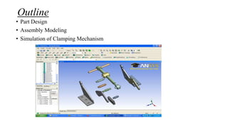
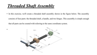
Clamping Mechanism
ANSYS Workbench
Name: Sanjeet Kumar Singh
Outline
• Part Design
• Assembly Modeling
• Simulation of Clamping Mechanism
Part Design
In this section, make all the necessary parts which are use in assembly
of Clamping Mechanism. The part created in this section are
1. Crank
2. Support
3. Threaded Shaft
4. Pin
Crank
• In this exercise, we'll create a 3D solid model for a crank, of which the details are shown in the
figure below. The crank model can be viewed as a series of three two-step operations; each
involves drawing a sketch on XY Plane and then extrude the sketch to generate a material.
Materials are either add to the existing body or cut from the existing body.
The 3D model of crank which are made in ANSYS DM as shown in figure below
Support
• The support is a part of the clamping mechanism. In this exercise, we'll create a 3D solid model for
the support, of which the details are shown in the multi view drawings below.
Threaded Shaft
• The threaded shaft is a part of the clamping mechanism. In this exercise, we create a 3D solid
model for the threaded shaft, of which the details are shown below.
Pin
Assembly Modeling
• An assembly consists of two or more parts. The Design Modeler assigns a color for each part in an
assembly. Creating a simple assembly is straightforward, but for complicated assembly, it is very
important to take care of those part which are used in assembly are not bonded together. This
usually can be done by freezing the existing parts. Creating complex assemblies involves
transformations (translations, rotations, etc.) of parts to appropriate positions.
Threaded Shaft Assembly
• In this exercise, we'll create a threaded shaft assembly shown in the figure below. The assembly
consists of four parts: the threaded shaft, a handle, and two hinges. This assembly is simple enough
that all parts can be created with referring to the same coordinate system.
•
After Assembly
Simulation of Clamping Mechanism
• Introduction
The clamping mechanism is designed to provide clamping forces up to 250 lbf. In this exercise, we
performed a simulation to make sure that, under the clamping force of 250 lbf, the stresses
everywhere are within the allowable stress of the steel, which is 30,000 psi because the clamping
mechanism is entirely made of steel, which is the default material used in ANSYS . We assume an
initial configuration such that the grip merely contacts the clamped object and the clamping force is
zero. As the handle rotates to increase the distance between two hinges, the clamping force also
increases, until the clamping force reaches 250 lbf.
Thank You

Clamping mechanism

  • 1.
  • 2.
    Outline • Part Design •Assembly Modeling • Simulation of Clamping Mechanism
  • 3.
    Part Design In thissection, make all the necessary parts which are use in assembly of Clamping Mechanism. The part created in this section are 1. Crank 2. Support 3. Threaded Shaft 4. Pin
  • 4.
    Crank • In thisexercise, we'll create a 3D solid model for a crank, of which the details are shown in the figure below. The crank model can be viewed as a series of three two-step operations; each involves drawing a sketch on XY Plane and then extrude the sketch to generate a material. Materials are either add to the existing body or cut from the existing body.
  • 5.
    The 3D modelof crank which are made in ANSYS DM as shown in figure below
  • 6.
    Support • The supportis a part of the clamping mechanism. In this exercise, we'll create a 3D solid model for the support, of which the details are shown in the multi view drawings below.
  • 8.
    Threaded Shaft • Thethreaded shaft is a part of the clamping mechanism. In this exercise, we create a 3D solid model for the threaded shaft, of which the details are shown below.
  • 10.
  • 11.
    Assembly Modeling • Anassembly consists of two or more parts. The Design Modeler assigns a color for each part in an assembly. Creating a simple assembly is straightforward, but for complicated assembly, it is very important to take care of those part which are used in assembly are not bonded together. This usually can be done by freezing the existing parts. Creating complex assemblies involves transformations (translations, rotations, etc.) of parts to appropriate positions.
  • 12.
    Threaded Shaft Assembly •In this exercise, we'll create a threaded shaft assembly shown in the figure below. The assembly consists of four parts: the threaded shaft, a handle, and two hinges. This assembly is simple enough that all parts can be created with referring to the same coordinate system. •
  • 14.
  • 17.
    Simulation of ClampingMechanism • Introduction The clamping mechanism is designed to provide clamping forces up to 250 lbf. In this exercise, we performed a simulation to make sure that, under the clamping force of 250 lbf, the stresses everywhere are within the allowable stress of the steel, which is 30,000 psi because the clamping mechanism is entirely made of steel, which is the default material used in ANSYS . We assume an initial configuration such that the grip merely contacts the clamped object and the clamping force is zero. As the handle rotates to increase the distance between two hinges, the clamping force also increases, until the clamping force reaches 250 lbf.
  • 29.