
Downloaded 313 times

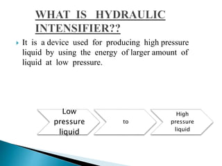
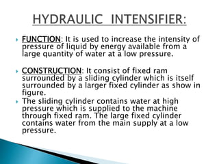
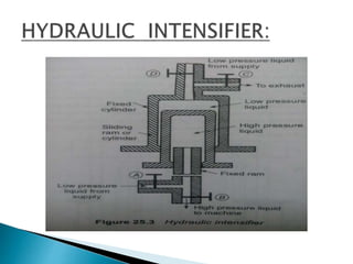
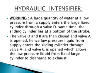
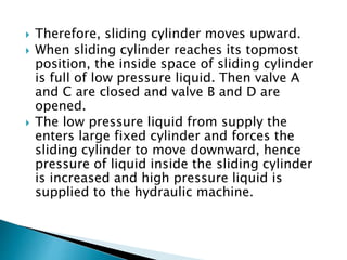
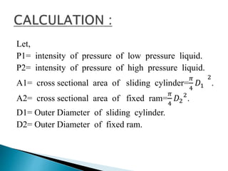
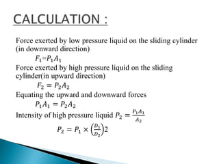

The document describes a hydraulic intensifier that converts low-pressure liquid into high-pressure liquid using a fixed ram and sliding cylinder structure. It details the device's construction, working mechanism, and applications such as in hydraulic presses and cranes. The intensifier requires a supply of low-pressure liquid to generate high pressure needed for various industrial applications.


![chapterfive [Autosaved].ppt](https://cdn.slidesharecdn.com/ss_thumbnails/chapterfiveautosaved-221227191443-4b610bb9-thumbnail.jpg?width=640&height=640&fit=bounds)


