Download as PDF, PPTX

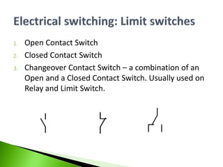
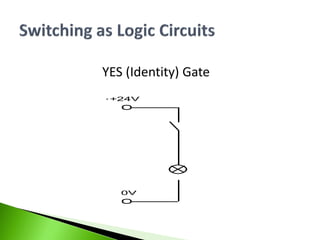

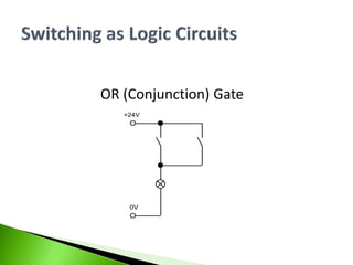
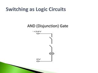
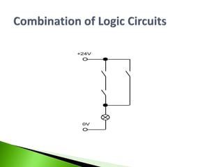
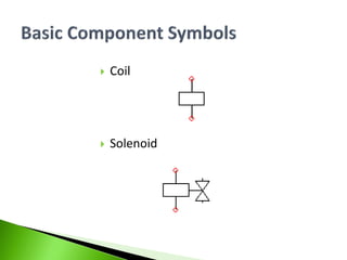
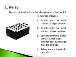
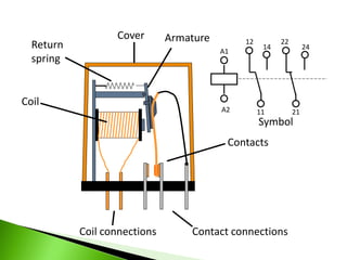
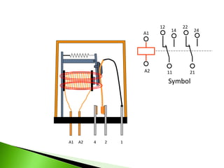

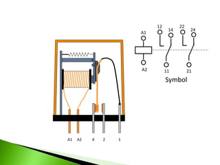
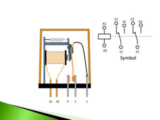
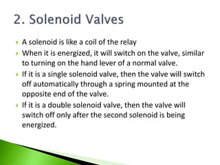
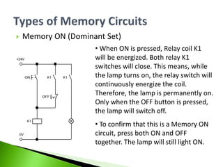
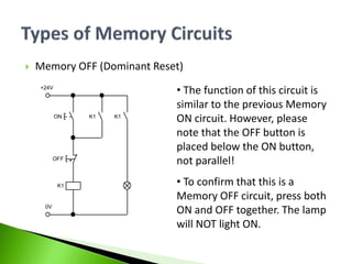

This document provides information on electro-hydraulic components including open/closed contact switches, relays, coils, solenoids, and logic circuits. It explains the symbols and functions of these components and how they are used in series and parallel circuits. Memory circuits are also discussed, along with examples of a memory on and memory off circuit. Relays are described as helping to switch small currents to larger ones and providing safety and interlocking capabilities. Solenoids function to switch valves on and off based on being energized or not.


