Downloaded 291 times

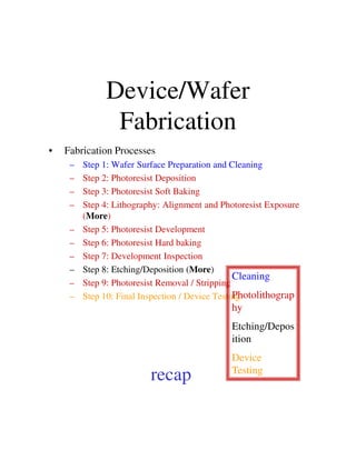
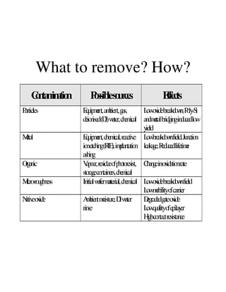
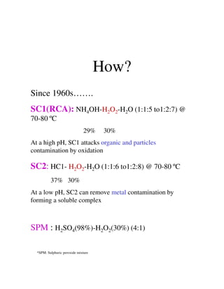
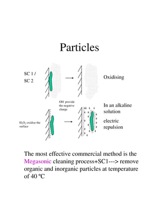
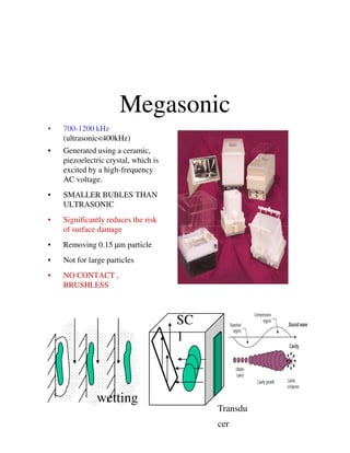
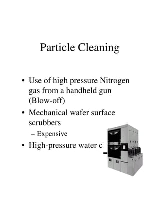
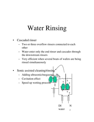
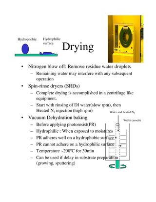
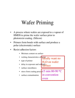
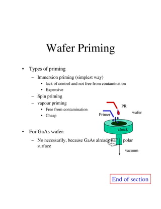

The document discusses wafer cleaning techniques which are the most important step in the wafer fabrication process. It describes various sources of contamination on wafer surfaces like particles, metals, organics and how they can affect device performance. Standard cleaning procedures using wet chemical solutions like SC1, SC2, sulfuric acid mixtures and advanced techniques like megasonic cleaning are explained. The key steps of cleaning, rinsing with deionized water and drying the wafers are outlined. Priming the wafer surface before photoresist coating is also summarized.


