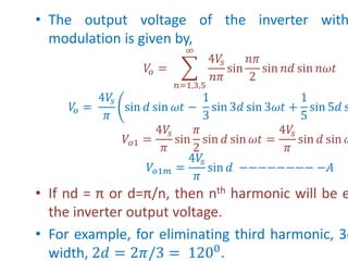
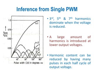
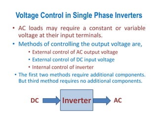
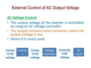
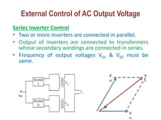
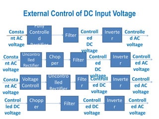
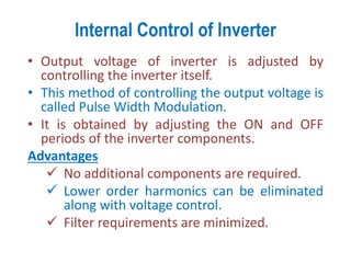
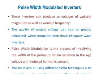
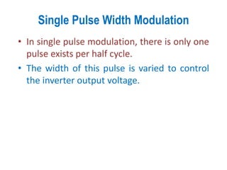
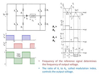
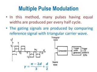
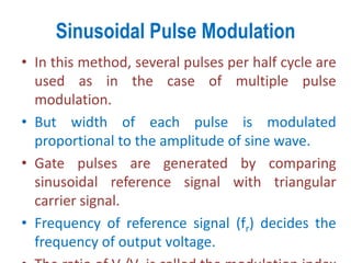
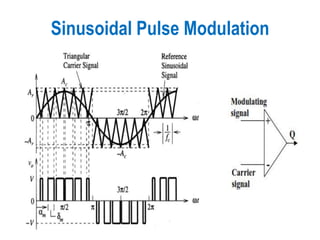
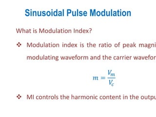
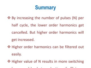
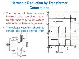
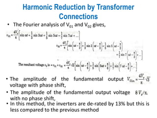
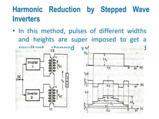
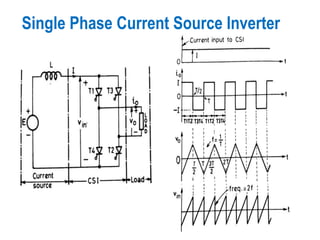
SlideShare a Scribd company logo
Inverters
Prepared by,
Mr. A.Johny Renoald M.E., Ph.D,
Voltage Control in Single Phase Inverters
• AC loads may require a constant or variable
voltage at their input terminals.
• Methods of controlling the output voltage are,
• External control of AC output voltage
• External control of DC input voltage
• Internal control of inverter
• The first two methods require additional components.
But third method requires no additional components.
Inverter
DC AC
External Control of AC Output Voltage
AC Voltage Control
• The output voltage of the inverter is controlled
by using an AC voltage controller.
• The output contains more harmonics when the
output voltage is low.
• Hence it is rarely used.
Inverte
r
AC
Voltage
Controlle
r
AC
Load
Controlle
d AC
voltage
Consta
nt DC
voltage
Consta
nt AC
voltage
External Control of AC Output Voltage
Series Inverter Control
• Two or more inverters are connected in parallel.
• Output of inverters are connected to transformers
whose secondary windings are connected in series.
• Frequency of output voltages V01 & V02 must be
same.
ϴ
V
02
V
01
V
O
External Control of DC Input Voltage
Fully
Controlle
d
Rectifier
Filter
Inverte
r
Controlle
d AC
voltage
Controll
ed
DC
voltage
Consta
nt AC
voltage
Uncontro
lled
Rectifier
Filter
Inverte
r
Controll
ed AC
voltage
Chop
per
AC
Voltage
Controll
er
Filte
r
Inverte
r
Controll
ed DC
voltage
Uncontro
lled
Rectifier
Chopp
er
Filter
Inverte
r
Controll
ed AC
voltage
Controll
ed DC
voltage
Control
led DC
voltage
Controll
ed
DC
voltage
Consta
nt AC
voltage
Controll
ed AC
voltage
Consta
nt AC
voltage
Internal Control of Inverter
• Output voltage of inverter is adjusted by
controlling the inverter itself.
• This method of controlling the output voltage is
called Pulse Width Modulation.
• It is obtained by adjusting the ON and OFF
periods of the inverter components.
Advantages
 No additional components are required.
 Lower order harmonics can be eliminated
along with voltage control.
 Filter requirements are minimized.
Pulse Width Modulated Inverters
• These inverters can produce ac voltages of variable
magnitude as well as variable frequency.
• The quality of output voltage can also be greatly
enhanced, when compared with those of square wave
inverters.
• Pulse Width Modulation is the process of modifying
the width of the pulses to obtain variation in the o/p
voltage with reduced harmonic content.
• The main aim of using different PWM techniques is to
Different types of PWM inverters
 Single pulse modulation
 Multiple pulse modulation
 Sinusoidal pulse modulation
 Modified sinusoidal pulse
modulation
 Space vector pulse width
modulation
Single Pulse Width Modulation
• In single pulse modulation, there is only one
pulse exists per half cycle.
• The width of this pulse is varied to control
the inverter output voltage.
• Frequency of the reference signal determines
the frequency of output voltage.
• The ratio of Ar to AC, called modulation index,
controls the output voltage.
Ar >
AC
Ar <
AC
• The output voltage of the inverter with
modulation is given by,
𝑉
𝑜 =
𝑛=1,3,5
∞
4𝑉
𝑠
𝑛𝜋
sin
𝑛𝜋
2
sin 𝑛𝑑 sin 𝑛𝜔𝑡
𝑉
𝑜 =
4𝑉
𝑠
𝜋
sin 𝑑 sin 𝜔𝑡 −
1
3
sin 3𝑑 sin 3𝜔𝑡 +
1
5
sin 5𝑑 s
𝑉𝑜1 =
4𝑉
𝑠
𝜋
sin
𝜋
2
sin 𝑑 sin 𝜔𝑡 =
4𝑉
𝑠
𝜋
sin 𝑑 sin 𝜔
𝑉𝑜1𝑚 =
4𝑉
𝑠
𝜋
sin 𝑑 −−−−−−−− −𝐴
• If nd = π or d=π/n, then nth harmonic will be e
the inverter output voltage.
• For example, for eliminating third harmonic, 3d
width, 2𝑑 = 2𝜋/3 = 1200
.
Inference from Single PWM
• 3rd, 5th & 7th harmonics
dominate when the voltage
is reduced.
• A large amount of
harmonics is introduced at
lower output voltages.
• Harmonic content can be
reduced by having many
pulses in each half cycle of
output voltage.
Multiple Pulse Modulation
• In this method, many pulses having equal
widths are produced per every half cycle.
• The gating signals are produced by comparing
reference signal with triangular carrier wave.
𝜸 =
𝝅 − 𝟐𝒅
𝟑
+
𝒅
𝟐
Multiple Pulse Modulation
• Frequency of the reference signal determines
the frequency of output voltage.
• The ratio of Ar to AC, called modulation index,
controls the output voltage.
• The output voltage waveform can be expressed in Fourier s
𝑉
𝑜 =
𝑛=1,3,5
∞
8𝑉
𝑠
𝑛𝜋
sin nγ sin
𝑛𝑑
2
sin 𝑛𝜔𝑡
𝑉
𝑜 =
8𝑉
𝑠
𝜋
sin 𝛾 sin
𝑑
2
sin 𝜔𝑡 −
1
3
sin 3𝛾 sin
3𝑑
2
sin
+
1
5
sin 5𝛾 sin
5𝑑
2
sin 5𝜔𝑡 … . .
𝑉𝑜1 =
8𝑉
𝑠
𝜋
sin γ sin
𝑑
2
sin 𝜔𝑡
𝑉𝑜1𝑚 =
8𝑉
𝑠
𝜋
sin γ sin
𝑑
2
−−−−− −𝐵
• For example, take pulse width 2d = 720.
• In single pulse modulation, the peak value of fundamental
𝑉𝑜1𝑚 =
4𝑉𝑆
𝜋
sin 𝑑 =
4𝑉𝑆
𝜋
sin 36 = 𝟎. 𝟕𝟒𝟖𝟒 𝑽
• In two pulse modulation, the peak value of fundamental vo
𝑉𝑜1𝑚 =
8𝑉𝑆
𝜋
sin 𝛾 sin
𝑑
2
𝛾 =
180 − 72
3
+
36
2
= 540
𝑉𝑜1𝑚 =
8𝑉𝑆
𝜋
sin 54 sin 18 = 𝟎. 𝟔𝟑𝟕 𝑽𝑺
Multiple Pulse Modulation
• It is seen from the above that the fundamental
component of output voltage is low for two pulse
modulation than it is for single pulse modulation.
• But lower order harmonics are eliminated and higher
order harmonics are increased. But higher order
harmonics can be filtered easily.
• This scheme is advantageous than single pulse
modulation.
• But large number of pulses per half cycle requires
Sinusoidal Pulse Modulation
• In this method, several pulses per half cycle are
used as in the case of multiple pulse
modulation.
• But width of each pulse is modulated
proportional to the amplitude of sine wave.
• Gate pulses are generated by comparing
sinusoidal reference signal with triangular
carrier signal.
• Frequency of reference signal (fr) decides the
frequency of output voltage.
Sinusoidal Pulse Modulation
What is Modulation Index?
 Modulation index is the ratio of peak magni
modulating waveform and the carrier waveform
𝑚 =
𝑉
𝑚
𝑉
𝑐
 MI controls the harmonic content in the outpu
Summary
 By increasing the number of pulses (N) per
half cycle, the lower order harmonics get
cancelled. But higher order harmonics will
get increased.
 Higher order harmonics can be filtered out
easily.
 Higher value of N results in more switching
Sinusoidal Pulse Modulation
What is Over Modulation?
• When the peak magnitude of modulating
signal exceeds the peak magnitude of
carrier signal, the PWM inverter operates
under over-modulation.
• During over-modulation the output voltage
increases slightly.
Reduction of Harmonics in the Inverter
O/P
• Harmonics of 5% is allowable in an inverter output
voltage.
• But inverter output voltage contains more than 5% of
harmonics.
• Filters can be used to reduce the harmonic content.
• Small size filter is enough for reducing higher order
harmonics.
• But a bigger size filter is required for reducing lower
Harmonic Reduction by PWM
• Several pulses per half cycle reduces the
lower order harmonics.
• As the waveform is symmetrical during every
quarter cycle, an=0.
• If 3rd and 5th harmonics are to be eliminated,
• Using α1 and α2, voltages of 7th, 9th and 11th
harmonics are found as,
• The amplitude of the fundamental
component for these values of α1 and α2 is,
• The amplitude of the fundamental component of
un modulated output voltage wave is,
• The amplitude of the fundamental voltage is
83.91% of the un modulated wave. So inverter is
de-rated by 16.09%.
• Additional eight commutation per cycle increases
switching losses.
Harmonic Reduction by Transformer
Connections
• The output of two or more
inverters are combined using
transformers to get a net voltage
with reduced harmonic content.
• The voltage waveform should be
similar but phase shifted from
each other.
Harmonic Reduction by Transformer
Connections
• The Fourier analysis of V01 and V02 gives,
• The amplitude of the fundamental output
voltage with phase shift,
• The amplitude of the fundamental output voltage
with no phase shift,
• In this method, the inverters are de-rated by 13% but this is
less compared to the previous method
Harmonic Reduction by Stepped Wave
Inverters
• In this method, pulses of different widths
and heights are super imposed to get a
resultant stepped wave with reduced
harmonic content.
Voltage Source
Inverters
Input voltage is
constant
Output voltage
does not depend
on load
Magnitude of
load current & its
shape depends
on load
Current Source
Inverters
Input current is
constant
Output current
does not depend
on load
Magnitude of
load voltage & its
shape depends
on load
Single Phase Current Source Inverter

More Related Content

What's hot

Multi level inverter
Multi level inverterMulti level inverter
Multi level inverter
Hamza saeed Khan
 
Current source inverter
Current source inverterCurrent source inverter
Current source inverter
Prashant Kumar
 
Unit 4 inverters (part-1)
Unit 4 inverters (part-1)Unit 4 inverters (part-1)
Unit 4 inverters (part-1)
johny renoald
 
Space Vector Modulation(SVM) Technique for PWM Inverter
Space Vector Modulation(SVM) Technique for PWM InverterSpace Vector Modulation(SVM) Technique for PWM Inverter
Space Vector Modulation(SVM) Technique for PWM Inverter
Purushotam Kumar
 
Pulse width modulated inverter
Pulse width modulated inverterPulse width modulated inverter
Pulse width modulated inverter
VSRAGHU
 
Flying Capacitor Multi Level Inverter
Flying Capacitor Multi Level InverterFlying Capacitor Multi Level Inverter
Flying Capacitor Multi Level Inverter
Sajid Sheikh
 
INTERLINE FLOW CONTROLLER
INTERLINE FLOW CONTROLLERINTERLINE FLOW CONTROLLER
INTERLINE FLOW CONTROLLER
Nitish NIT
 
three phase inverter
three phase inverterthree phase inverter
three phase inverterMalik Zaid
 
Report On diode clamp three level inverter
Report On diode clamp three level inverterReport On diode clamp three level inverter
Report On diode clamp three level inverter
Vinay Singh
 
vector control of induction motor
vector control of induction motorvector control of induction motor
vector control of induction motor
Dwaraka Pilla
 
Unit iv-inverters-new
Unit iv-inverters-newUnit iv-inverters-new
Unit iv-inverters-new
Sakthivel Ganesan
 
Unit 2.Converter and Chopper fed Dc drives
Unit 2.Converter and Chopper fed Dc drivesUnit 2.Converter and Chopper fed Dc drives
Unit 2.Converter and Chopper fed Dc drives
raviarmugam
 
Single phase full bridge inverter
Single phase full bridge inverterSingle phase full bridge inverter
Single phase full bridge inverter
Nisarg Amin
 
Power electronics Introduction
Power electronics   IntroductionPower electronics   Introduction
Power electronics Introduction
Burdwan University
 
Resonant Inverters
Resonant InvertersResonant Inverters
Resonant Inverters
raviarmugam
 
INVERTERS PRESENTATION
INVERTERS PRESENTATIONINVERTERS PRESENTATION
INVERTERS PRESENTATION
Rajesh V
 
VSC based HVDC system
VSC based HVDC systemVSC based HVDC system
VSC based HVDC system
mdhsudhan
 
Inverter
InverterInverter
Inverter
Somu Gupta
 
Multilevel inverter
Multilevel inverterMultilevel inverter
Multilevel inverter
ak dixit
 

What's hot (20)

Multi level inverter
Multi level inverterMulti level inverter
Multi level inverter
 
Current source inverter
Current source inverterCurrent source inverter
Current source inverter
 
Unit 4 inverters (part-1)
Unit 4 inverters (part-1)Unit 4 inverters (part-1)
Unit 4 inverters (part-1)
 
Dc fed chopper
Dc fed chopperDc fed chopper
Dc fed chopper
 
Space Vector Modulation(SVM) Technique for PWM Inverter
Space Vector Modulation(SVM) Technique for PWM InverterSpace Vector Modulation(SVM) Technique for PWM Inverter
Space Vector Modulation(SVM) Technique for PWM Inverter
 
Pulse width modulated inverter
Pulse width modulated inverterPulse width modulated inverter
Pulse width modulated inverter
 
Flying Capacitor Multi Level Inverter
Flying Capacitor Multi Level InverterFlying Capacitor Multi Level Inverter
Flying Capacitor Multi Level Inverter
 
INTERLINE FLOW CONTROLLER
INTERLINE FLOW CONTROLLERINTERLINE FLOW CONTROLLER
INTERLINE FLOW CONTROLLER
 
three phase inverter
three phase inverterthree phase inverter
three phase inverter
 
Report On diode clamp three level inverter
Report On diode clamp three level inverterReport On diode clamp three level inverter
Report On diode clamp three level inverter
 
vector control of induction motor
vector control of induction motorvector control of induction motor
vector control of induction motor
 
Unit iv-inverters-new
Unit iv-inverters-newUnit iv-inverters-new
Unit iv-inverters-new
 
Unit 2.Converter and Chopper fed Dc drives
Unit 2.Converter and Chopper fed Dc drivesUnit 2.Converter and Chopper fed Dc drives
Unit 2.Converter and Chopper fed Dc drives
 
Single phase full bridge inverter
Single phase full bridge inverterSingle phase full bridge inverter
Single phase full bridge inverter
 
Power electronics Introduction
Power electronics   IntroductionPower electronics   Introduction
Power electronics Introduction
 
Resonant Inverters
Resonant InvertersResonant Inverters
Resonant Inverters
 
INVERTERS PRESENTATION
INVERTERS PRESENTATIONINVERTERS PRESENTATION
INVERTERS PRESENTATION
 
VSC based HVDC system
VSC based HVDC systemVSC based HVDC system
VSC based HVDC system
 
Inverter
InverterInverter
Inverter
 
Multilevel inverter
Multilevel inverterMultilevel inverter
Multilevel inverter
 

Similar to Unit- 4 inverters (part-2)

Sinusoidal pwm
Sinusoidal pwmSinusoidal pwm
Sinusoidal pwm
Chintan Hansalia
 
Inverter
InverterInverter
Inverter
raguprince
 
Design and Simulation of Low Pass Filter for Single phase full bridge Inverte...
Design and Simulation of Low Pass Filter for Single phase full bridge Inverte...Design and Simulation of Low Pass Filter for Single phase full bridge Inverte...
Design and Simulation of Low Pass Filter for Single phase full bridge Inverte...
IJERA Editor
 
power electronics(ii)
power electronics(ii)power electronics(ii)
power electronics(ii)
Darya khan
 
differentmethodsofpwmforinvertercontrol-171103170201.pdf
differentmethodsofpwmforinvertercontrol-171103170201.pdfdifferentmethodsofpwmforinvertercontrol-171103170201.pdf
differentmethodsofpwmforinvertercontrol-171103170201.pdf
MdSazibMollik
 
Different methods of pwm for inverter control
Different methods of pwm for inverter controlDifferent methods of pwm for inverter control
Different methods of pwm for inverter control
Tushar Pandagre
 
AC Signal Sources.
AC Signal Sources.AC Signal Sources.
AC Signal Sources.
Dhairya Gandha
 
Study of Different Types of Inverters and FFT Analysis of Output of SPWM Inve...
Study of Different Types of Inverters and FFT Analysis of Output of SPWM Inve...Study of Different Types of Inverters and FFT Analysis of Output of SPWM Inve...
Study of Different Types of Inverters and FFT Analysis of Output of SPWM Inve...
RSIS International
 
Lecture slides_Ch 8 power electronics daniel hart.pdf
Lecture slides_Ch 8 power electronics daniel hart.pdfLecture slides_Ch 8 power electronics daniel hart.pdf
Lecture slides_Ch 8 power electronics daniel hart.pdf
GIFT University, Gujranwala, Pakistan
 
Simulation of sinosoidal pulse width modulation
Simulation of sinosoidal pulse width modulationSimulation of sinosoidal pulse width modulation
Simulation of sinosoidal pulse width modulation
Tanzeel Ahmad
 
Unit 2 signal generators
Unit 2 signal generatorsUnit 2 signal generators
Unit 2 signal generators
Tejas Prajapati
 
Power Electronics - Phase Controlled Converters.pptx
Power Electronics - Phase Controlled Converters.pptxPower Electronics - Phase Controlled Converters.pptx
Power Electronics - Phase Controlled Converters.pptx
Poornima D
 
22 PulseModulation.pdf
22 PulseModulation.pdf22 PulseModulation.pdf
22 PulseModulation.pdf
Mohamedshabana38
 
Edge multi phase low latency pulse width modulator
Edge multi phase low latency pulse width modulatorEdge multi phase low latency pulse width modulator
Edge multi phase low latency pulse width modulator
yc2levgmail
 
Voltmeter
VoltmeterVoltmeter
Voltmeter
vaibhav jindal
 
EMI Unit II
EMI Unit IIEMI Unit II
EMI Unit II
GVNSK Sravya
 
Multilevel Inverters [Autosaved].pptx
Multilevel Inverters [Autosaved].pptxMultilevel Inverters [Autosaved].pptx
Multilevel Inverters [Autosaved].pptx
AriefBudianto13
 
Power Converters for AC drives CH-1.pptx
Power Converters for AC drives CH-1.pptxPower Converters for AC drives CH-1.pptx
Power Converters for AC drives CH-1.pptx
SuvenduMondal12
 
Analog pulse modulation scheme.pptx
Analog pulse modulation scheme.pptxAnalog pulse modulation scheme.pptx
Analog pulse modulation scheme.pptx
swatihalunde
 
Averaging - 1.docx
Averaging - 1.docxAveraging - 1.docx
Averaging - 1.docx
sougataghosh1984
 

Similar to Unit- 4 inverters (part-2) (20)

Sinusoidal pwm
Sinusoidal pwmSinusoidal pwm
Sinusoidal pwm
 
Inverter
InverterInverter
Inverter
 
Design and Simulation of Low Pass Filter for Single phase full bridge Inverte...
Design and Simulation of Low Pass Filter for Single phase full bridge Inverte...Design and Simulation of Low Pass Filter for Single phase full bridge Inverte...
Design and Simulation of Low Pass Filter for Single phase full bridge Inverte...
 
power electronics(ii)
power electronics(ii)power electronics(ii)
power electronics(ii)
 
differentmethodsofpwmforinvertercontrol-171103170201.pdf
differentmethodsofpwmforinvertercontrol-171103170201.pdfdifferentmethodsofpwmforinvertercontrol-171103170201.pdf
differentmethodsofpwmforinvertercontrol-171103170201.pdf
 
Different methods of pwm for inverter control
Different methods of pwm for inverter controlDifferent methods of pwm for inverter control
Different methods of pwm for inverter control
 
AC Signal Sources.
AC Signal Sources.AC Signal Sources.
AC Signal Sources.
 
Study of Different Types of Inverters and FFT Analysis of Output of SPWM Inve...
Study of Different Types of Inverters and FFT Analysis of Output of SPWM Inve...Study of Different Types of Inverters and FFT Analysis of Output of SPWM Inve...
Study of Different Types of Inverters and FFT Analysis of Output of SPWM Inve...
 
Lecture slides_Ch 8 power electronics daniel hart.pdf
Lecture slides_Ch 8 power electronics daniel hart.pdfLecture slides_Ch 8 power electronics daniel hart.pdf
Lecture slides_Ch 8 power electronics daniel hart.pdf
 
Simulation of sinosoidal pulse width modulation
Simulation of sinosoidal pulse width modulationSimulation of sinosoidal pulse width modulation
Simulation of sinosoidal pulse width modulation
 
Unit 2 signal generators
Unit 2 signal generatorsUnit 2 signal generators
Unit 2 signal generators
 
Power Electronics - Phase Controlled Converters.pptx
Power Electronics - Phase Controlled Converters.pptxPower Electronics - Phase Controlled Converters.pptx
Power Electronics - Phase Controlled Converters.pptx
 
22 PulseModulation.pdf
22 PulseModulation.pdf22 PulseModulation.pdf
22 PulseModulation.pdf
 
Edge multi phase low latency pulse width modulator
Edge multi phase low latency pulse width modulatorEdge multi phase low latency pulse width modulator
Edge multi phase low latency pulse width modulator
 
Voltmeter
VoltmeterVoltmeter
Voltmeter
 
EMI Unit II
EMI Unit IIEMI Unit II
EMI Unit II
 
Multilevel Inverters [Autosaved].pptx
Multilevel Inverters [Autosaved].pptxMultilevel Inverters [Autosaved].pptx
Multilevel Inverters [Autosaved].pptx
 
Power Converters for AC drives CH-1.pptx
Power Converters for AC drives CH-1.pptxPower Converters for AC drives CH-1.pptx
Power Converters for AC drives CH-1.pptx
 
Analog pulse modulation scheme.pptx
Analog pulse modulation scheme.pptxAnalog pulse modulation scheme.pptx
Analog pulse modulation scheme.pptx
 
Averaging - 1.docx
Averaging - 1.docxAveraging - 1.docx
Averaging - 1.docx
 

More from johny renoald

Necessity of starter in induction motor
Necessity of starter in induction motorNecessity of starter in induction motor
Necessity of starter in induction motor
johny renoald
 
Alternator and 3 phase induction motor
Alternator and 3 phase induction motorAlternator and 3 phase induction motor
Alternator and 3 phase induction motor
johny renoald
 
Special Electrical Machines
Special Electrical MachinesSpecial Electrical Machines
Special Electrical Machines
johny renoald
 
Single phase Transformer
Single phase Transformer  Single phase Transformer
Single phase Transformer
johny renoald
 
Power MOSFET
Power MOSFETPower MOSFET
Power MOSFET
johny renoald
 
SCR
SCR SCR
IGBT
IGBTIGBT
Unit- 3 DC-DC Converter
Unit- 3 DC-DC ConverterUnit- 3 DC-DC Converter
Unit- 3 DC-DC Converter
johny renoald
 
Unit2
Unit2Unit2
Protection & switchgear
Protection & switchgear   Protection & switchgear
Protection & switchgear
johny renoald
 
Protection & switchgear
Protection & switchgear   Protection & switchgear
Protection & switchgear
johny renoald
 
Protection & switchgear
Protection & switchgear  Protection & switchgear
Protection & switchgear
johny renoald
 
Protection & switchgear
Protection & switchgear   Protection & switchgear
Protection & switchgear
johny renoald
 
Protection & switchgear
Protection & switchgear   Protection & switchgear
Protection & switchgear
johny renoald
 
Introduction to Electricity
Introduction to Electricity Introduction to Electricity
Introduction to Electricity
johny renoald
 
Role of teachers
Role of teachersRole of teachers
Role of teachers
johny renoald
 
Management
Management Management
Management
johny renoald
 
Communication skills
Communication skills Communication skills
Communication skills
johny renoald
 
Resume Preparation
Resume PreparationResume Preparation
Resume Preparation
johny renoald
 
I-unit
I-unitI-unit

More from johny renoald (20)

Necessity of starter in induction motor
Necessity of starter in induction motorNecessity of starter in induction motor
Necessity of starter in induction motor
 
Alternator and 3 phase induction motor
Alternator and 3 phase induction motorAlternator and 3 phase induction motor
Alternator and 3 phase induction motor
 
Special Electrical Machines
Special Electrical MachinesSpecial Electrical Machines
Special Electrical Machines
 
Single phase Transformer
Single phase Transformer  Single phase Transformer
Single phase Transformer
 
Power MOSFET
Power MOSFETPower MOSFET
Power MOSFET
 
SCR
SCR SCR
SCR
 
IGBT
IGBTIGBT
IGBT
 
Unit- 3 DC-DC Converter
Unit- 3 DC-DC ConverterUnit- 3 DC-DC Converter
Unit- 3 DC-DC Converter
 
Unit2
Unit2Unit2
Unit2
 
Protection & switchgear
Protection & switchgear   Protection & switchgear
Protection & switchgear
 
Protection & switchgear
Protection & switchgear   Protection & switchgear
Protection & switchgear
 
Protection & switchgear
Protection & switchgear  Protection & switchgear
Protection & switchgear
 
Protection & switchgear
Protection & switchgear   Protection & switchgear
Protection & switchgear
 
Protection & switchgear
Protection & switchgear   Protection & switchgear
Protection & switchgear
 
Introduction to Electricity
Introduction to Electricity Introduction to Electricity
Introduction to Electricity
 
Role of teachers
Role of teachersRole of teachers
Role of teachers
 
Management
Management Management
Management
 
Communication skills
Communication skills Communication skills
Communication skills
 
Resume Preparation
Resume PreparationResume Preparation
Resume Preparation
 
I-unit
I-unitI-unit
I-unit
 

Recently uploaded

Pile Foundation by Venkatesh Taduvai (Sub Geotechnical Engineering II)-conver...
Pile Foundation by Venkatesh Taduvai (Sub Geotechnical Engineering II)-conver...Pile Foundation by Venkatesh Taduvai (Sub Geotechnical Engineering II)-conver...
Pile Foundation by Venkatesh Taduvai (Sub Geotechnical Engineering II)-conver...
AJAYKUMARPUND1
 
Cosmetic shop management system project report.pdf
Cosmetic shop management system project report.pdfCosmetic shop management system project report.pdf
Cosmetic shop management system project report.pdf
Kamal Acharya
 
J.Yang, ICLR 2024, MLILAB, KAIST AI.pdf
J.Yang,  ICLR 2024, MLILAB, KAIST AI.pdfJ.Yang,  ICLR 2024, MLILAB, KAIST AI.pdf
J.Yang, ICLR 2024, MLILAB, KAIST AI.pdf
MLILAB
 
Gen AI Study Jams _ For the GDSC Leads in India.pdf
Gen AI Study Jams _ For the GDSC Leads in India.pdfGen AI Study Jams _ For the GDSC Leads in India.pdf
Gen AI Study Jams _ For the GDSC Leads in India.pdf
gdsczhcet
 
Governing Equations for Fundamental Aerodynamics_Anderson2010.pdf
Governing Equations for Fundamental Aerodynamics_Anderson2010.pdfGoverning Equations for Fundamental Aerodynamics_Anderson2010.pdf
Governing Equations for Fundamental Aerodynamics_Anderson2010.pdf
WENKENLI1
 
Investor-Presentation-Q1FY2024 investor presentation document.pptx
Investor-Presentation-Q1FY2024 investor presentation document.pptxInvestor-Presentation-Q1FY2024 investor presentation document.pptx
Investor-Presentation-Q1FY2024 investor presentation document.pptx
AmarGB2
 
ethical hacking-mobile hacking methods.ppt
ethical hacking-mobile hacking methods.pptethical hacking-mobile hacking methods.ppt
ethical hacking-mobile hacking methods.ppt
Jayaprasanna4
 
Architectural Portfolio Sean Lockwood
Architectural Portfolio Sean LockwoodArchitectural Portfolio Sean Lockwood
Architectural Portfolio Sean Lockwood
seandesed
 
block diagram and signal flow graph representation
block diagram and signal flow graph representationblock diagram and signal flow graph representation
block diagram and signal flow graph representation
Divya Somashekar
 
ethical hacking in wireless-hacking1.ppt
ethical hacking in wireless-hacking1.pptethical hacking in wireless-hacking1.ppt
ethical hacking in wireless-hacking1.ppt
Jayaprasanna4
 
Water Industry Process Automation and Control Monthly - May 2024.pdf
Water Industry Process Automation and Control Monthly - May 2024.pdfWater Industry Process Automation and Control Monthly - May 2024.pdf
Water Industry Process Automation and Control Monthly - May 2024.pdf
Water Industry Process Automation & Control
 
road safety engineering r s e unit 3.pdf
road safety engineering  r s e unit 3.pdfroad safety engineering  r s e unit 3.pdf
road safety engineering r s e unit 3.pdf
VENKATESHvenky89705
 
Top 10 Oil and Gas Projects in Saudi Arabia 2024.pdf
Top 10 Oil and Gas Projects in Saudi Arabia 2024.pdfTop 10 Oil and Gas Projects in Saudi Arabia 2024.pdf
Top 10 Oil and Gas Projects in Saudi Arabia 2024.pdf
Teleport Manpower Consultant
 
在线办理(ANU毕业证书)澳洲国立大学毕业证录取通知书一模一样
在线办理(ANU毕业证书)澳洲国立大学毕业证录取通知书一模一样在线办理(ANU毕业证书)澳洲国立大学毕业证录取通知书一模一样
在线办理(ANU毕业证书)澳洲国立大学毕业证录取通知书一模一样
obonagu
 
Final project report on grocery store management system..pdf
Final project report on grocery store management system..pdfFinal project report on grocery store management system..pdf
Final project report on grocery store management system..pdf
Kamal Acharya
 
Hierarchical Digital Twin of a Naval Power System
Hierarchical Digital Twin of a Naval Power SystemHierarchical Digital Twin of a Naval Power System
Hierarchical Digital Twin of a Naval Power System
Kerry Sado
 
NO1 Uk best vashikaran specialist in delhi vashikaran baba near me online vas...
NO1 Uk best vashikaran specialist in delhi vashikaran baba near me online vas...NO1 Uk best vashikaran specialist in delhi vashikaran baba near me online vas...
NO1 Uk best vashikaran specialist in delhi vashikaran baba near me online vas...
Amil Baba Dawood bangali
 
Immunizing Image Classifiers Against Localized Adversary Attacks
Immunizing Image Classifiers Against Localized Adversary AttacksImmunizing Image Classifiers Against Localized Adversary Attacks
Immunizing Image Classifiers Against Localized Adversary Attacks
gerogepatton
 
AKS UNIVERSITY Satna Final Year Project By OM Hardaha.pdf
AKS UNIVERSITY Satna Final Year Project By OM Hardaha.pdfAKS UNIVERSITY Satna Final Year Project By OM Hardaha.pdf
AKS UNIVERSITY Satna Final Year Project By OM Hardaha.pdf
SamSarthak3
 
AP LAB PPT.pdf ap lab ppt no title specific
AP LAB PPT.pdf ap lab ppt no title specificAP LAB PPT.pdf ap lab ppt no title specific
AP LAB PPT.pdf ap lab ppt no title specific
BrazilAccount1
 

Recently uploaded (20)

Pile Foundation by Venkatesh Taduvai (Sub Geotechnical Engineering II)-conver...
Pile Foundation by Venkatesh Taduvai (Sub Geotechnical Engineering II)-conver...Pile Foundation by Venkatesh Taduvai (Sub Geotechnical Engineering II)-conver...
Pile Foundation by Venkatesh Taduvai (Sub Geotechnical Engineering II)-conver...
 
Cosmetic shop management system project report.pdf
Cosmetic shop management system project report.pdfCosmetic shop management system project report.pdf
Cosmetic shop management system project report.pdf
 
J.Yang, ICLR 2024, MLILAB, KAIST AI.pdf
J.Yang,  ICLR 2024, MLILAB, KAIST AI.pdfJ.Yang,  ICLR 2024, MLILAB, KAIST AI.pdf
J.Yang, ICLR 2024, MLILAB, KAIST AI.pdf
 
Gen AI Study Jams _ For the GDSC Leads in India.pdf
Gen AI Study Jams _ For the GDSC Leads in India.pdfGen AI Study Jams _ For the GDSC Leads in India.pdf
Gen AI Study Jams _ For the GDSC Leads in India.pdf
 
Governing Equations for Fundamental Aerodynamics_Anderson2010.pdf
Governing Equations for Fundamental Aerodynamics_Anderson2010.pdfGoverning Equations for Fundamental Aerodynamics_Anderson2010.pdf
Governing Equations for Fundamental Aerodynamics_Anderson2010.pdf
 
Investor-Presentation-Q1FY2024 investor presentation document.pptx
Investor-Presentation-Q1FY2024 investor presentation document.pptxInvestor-Presentation-Q1FY2024 investor presentation document.pptx
Investor-Presentation-Q1FY2024 investor presentation document.pptx
 
ethical hacking-mobile hacking methods.ppt
ethical hacking-mobile hacking methods.pptethical hacking-mobile hacking methods.ppt
ethical hacking-mobile hacking methods.ppt
 
Architectural Portfolio Sean Lockwood
Architectural Portfolio Sean LockwoodArchitectural Portfolio Sean Lockwood
Architectural Portfolio Sean Lockwood
 
block diagram and signal flow graph representation
block diagram and signal flow graph representationblock diagram and signal flow graph representation
block diagram and signal flow graph representation
 
ethical hacking in wireless-hacking1.ppt
ethical hacking in wireless-hacking1.pptethical hacking in wireless-hacking1.ppt
ethical hacking in wireless-hacking1.ppt
 
Water Industry Process Automation and Control Monthly - May 2024.pdf
Water Industry Process Automation and Control Monthly - May 2024.pdfWater Industry Process Automation and Control Monthly - May 2024.pdf
Water Industry Process Automation and Control Monthly - May 2024.pdf
 
road safety engineering r s e unit 3.pdf
road safety engineering  r s e unit 3.pdfroad safety engineering  r s e unit 3.pdf
road safety engineering r s e unit 3.pdf
 
Top 10 Oil and Gas Projects in Saudi Arabia 2024.pdf
Top 10 Oil and Gas Projects in Saudi Arabia 2024.pdfTop 10 Oil and Gas Projects in Saudi Arabia 2024.pdf
Top 10 Oil and Gas Projects in Saudi Arabia 2024.pdf
 
在线办理(ANU毕业证书)澳洲国立大学毕业证录取通知书一模一样
在线办理(ANU毕业证书)澳洲国立大学毕业证录取通知书一模一样在线办理(ANU毕业证书)澳洲国立大学毕业证录取通知书一模一样
在线办理(ANU毕业证书)澳洲国立大学毕业证录取通知书一模一样
 
Final project report on grocery store management system..pdf
Final project report on grocery store management system..pdfFinal project report on grocery store management system..pdf
Final project report on grocery store management system..pdf
 
Hierarchical Digital Twin of a Naval Power System
Hierarchical Digital Twin of a Naval Power SystemHierarchical Digital Twin of a Naval Power System
Hierarchical Digital Twin of a Naval Power System
 
NO1 Uk best vashikaran specialist in delhi vashikaran baba near me online vas...
NO1 Uk best vashikaran specialist in delhi vashikaran baba near me online vas...NO1 Uk best vashikaran specialist in delhi vashikaran baba near me online vas...
NO1 Uk best vashikaran specialist in delhi vashikaran baba near me online vas...
 
Immunizing Image Classifiers Against Localized Adversary Attacks
Immunizing Image Classifiers Against Localized Adversary AttacksImmunizing Image Classifiers Against Localized Adversary Attacks
Immunizing Image Classifiers Against Localized Adversary Attacks
 
AKS UNIVERSITY Satna Final Year Project By OM Hardaha.pdf
AKS UNIVERSITY Satna Final Year Project By OM Hardaha.pdfAKS UNIVERSITY Satna Final Year Project By OM Hardaha.pdf
AKS UNIVERSITY Satna Final Year Project By OM Hardaha.pdf
 
AP LAB PPT.pdf ap lab ppt no title specific
AP LAB PPT.pdf ap lab ppt no title specificAP LAB PPT.pdf ap lab ppt no title specific
AP LAB PPT.pdf ap lab ppt no title specific
 

Unit- 4 inverters (part-2)

  • 2. Voltage Control in Single Phase Inverters • AC loads may require a constant or variable voltage at their input terminals. • Methods of controlling the output voltage are, • External control of AC output voltage • External control of DC input voltage • Internal control of inverter • The first two methods require additional components. But third method requires no additional components. Inverter DC AC
  • 3. External Control of AC Output Voltage AC Voltage Control • The output voltage of the inverter is controlled by using an AC voltage controller. • The output contains more harmonics when the output voltage is low. • Hence it is rarely used. Inverte r AC Voltage Controlle r AC Load Controlle d AC voltage Consta nt DC voltage Consta nt AC voltage
  • 4. External Control of AC Output Voltage Series Inverter Control • Two or more inverters are connected in parallel. • Output of inverters are connected to transformers whose secondary windings are connected in series. • Frequency of output voltages V01 & V02 must be same. ϴ V 02 V 01 V O
  • 5. External Control of DC Input Voltage Fully Controlle d Rectifier Filter Inverte r Controlle d AC voltage Controll ed DC voltage Consta nt AC voltage Uncontro lled Rectifier Filter Inverte r Controll ed AC voltage Chop per AC Voltage Controll er Filte r Inverte r Controll ed DC voltage Uncontro lled Rectifier Chopp er Filter Inverte r Controll ed AC voltage Controll ed DC voltage Control led DC voltage Controll ed DC voltage Consta nt AC voltage Controll ed AC voltage Consta nt AC voltage
  • 6. Internal Control of Inverter • Output voltage of inverter is adjusted by controlling the inverter itself. • This method of controlling the output voltage is called Pulse Width Modulation. • It is obtained by adjusting the ON and OFF periods of the inverter components. Advantages  No additional components are required.  Lower order harmonics can be eliminated along with voltage control.  Filter requirements are minimized.
  • 7. Pulse Width Modulated Inverters • These inverters can produce ac voltages of variable magnitude as well as variable frequency. • The quality of output voltage can also be greatly enhanced, when compared with those of square wave inverters. • Pulse Width Modulation is the process of modifying the width of the pulses to obtain variation in the o/p voltage with reduced harmonic content. • The main aim of using different PWM techniques is to
  • 8. Different types of PWM inverters  Single pulse modulation  Multiple pulse modulation  Sinusoidal pulse modulation  Modified sinusoidal pulse modulation  Space vector pulse width modulation
  • 9. Single Pulse Width Modulation • In single pulse modulation, there is only one pulse exists per half cycle. • The width of this pulse is varied to control the inverter output voltage.
  • 10. • Frequency of the reference signal determines the frequency of output voltage. • The ratio of Ar to AC, called modulation index, controls the output voltage. Ar > AC Ar < AC
  • 11. • The output voltage of the inverter with modulation is given by, 𝑉 𝑜 = 𝑛=1,3,5 ∞ 4𝑉 𝑠 𝑛𝜋 sin 𝑛𝜋 2 sin 𝑛𝑑 sin 𝑛𝜔𝑡 𝑉 𝑜 = 4𝑉 𝑠 𝜋 sin 𝑑 sin 𝜔𝑡 − 1 3 sin 3𝑑 sin 3𝜔𝑡 + 1 5 sin 5𝑑 s 𝑉𝑜1 = 4𝑉 𝑠 𝜋 sin 𝜋 2 sin 𝑑 sin 𝜔𝑡 = 4𝑉 𝑠 𝜋 sin 𝑑 sin 𝜔 𝑉𝑜1𝑚 = 4𝑉 𝑠 𝜋 sin 𝑑 −−−−−−−− −𝐴 • If nd = π or d=π/n, then nth harmonic will be e the inverter output voltage. • For example, for eliminating third harmonic, 3d width, 2𝑑 = 2𝜋/3 = 1200 .
  • 12. Inference from Single PWM • 3rd, 5th & 7th harmonics dominate when the voltage is reduced. • A large amount of harmonics is introduced at lower output voltages. • Harmonic content can be reduced by having many pulses in each half cycle of output voltage.
  • 13. Multiple Pulse Modulation • In this method, many pulses having equal widths are produced per every half cycle. • The gating signals are produced by comparing reference signal with triangular carrier wave. 𝜸 = 𝝅 − 𝟐𝒅 𝟑 + 𝒅 𝟐
  • 14. Multiple Pulse Modulation • Frequency of the reference signal determines the frequency of output voltage. • The ratio of Ar to AC, called modulation index, controls the output voltage.
  • 15. • The output voltage waveform can be expressed in Fourier s 𝑉 𝑜 = 𝑛=1,3,5 ∞ 8𝑉 𝑠 𝑛𝜋 sin nγ sin 𝑛𝑑 2 sin 𝑛𝜔𝑡 𝑉 𝑜 = 8𝑉 𝑠 𝜋 sin 𝛾 sin 𝑑 2 sin 𝜔𝑡 − 1 3 sin 3𝛾 sin 3𝑑 2 sin + 1 5 sin 5𝛾 sin 5𝑑 2 sin 5𝜔𝑡 … . . 𝑉𝑜1 = 8𝑉 𝑠 𝜋 sin γ sin 𝑑 2 sin 𝜔𝑡 𝑉𝑜1𝑚 = 8𝑉 𝑠 𝜋 sin γ sin 𝑑 2 −−−−− −𝐵
  • 16. • For example, take pulse width 2d = 720. • In single pulse modulation, the peak value of fundamental 𝑉𝑜1𝑚 = 4𝑉𝑆 𝜋 sin 𝑑 = 4𝑉𝑆 𝜋 sin 36 = 𝟎. 𝟕𝟒𝟖𝟒 𝑽 • In two pulse modulation, the peak value of fundamental vo 𝑉𝑜1𝑚 = 8𝑉𝑆 𝜋 sin 𝛾 sin 𝑑 2 𝛾 = 180 − 72 3 + 36 2 = 540 𝑉𝑜1𝑚 = 8𝑉𝑆 𝜋 sin 54 sin 18 = 𝟎. 𝟔𝟑𝟕 𝑽𝑺
  • 17. Multiple Pulse Modulation • It is seen from the above that the fundamental component of output voltage is low for two pulse modulation than it is for single pulse modulation. • But lower order harmonics are eliminated and higher order harmonics are increased. But higher order harmonics can be filtered easily. • This scheme is advantageous than single pulse modulation. • But large number of pulses per half cycle requires
  • 18. Sinusoidal Pulse Modulation • In this method, several pulses per half cycle are used as in the case of multiple pulse modulation. • But width of each pulse is modulated proportional to the amplitude of sine wave. • Gate pulses are generated by comparing sinusoidal reference signal with triangular carrier signal. • Frequency of reference signal (fr) decides the frequency of output voltage.
  • 20. Sinusoidal Pulse Modulation What is Modulation Index?  Modulation index is the ratio of peak magni modulating waveform and the carrier waveform 𝑚 = 𝑉 𝑚 𝑉 𝑐  MI controls the harmonic content in the outpu
  • 21. Summary  By increasing the number of pulses (N) per half cycle, the lower order harmonics get cancelled. But higher order harmonics will get increased.  Higher order harmonics can be filtered out easily.  Higher value of N results in more switching
  • 22. Sinusoidal Pulse Modulation What is Over Modulation? • When the peak magnitude of modulating signal exceeds the peak magnitude of carrier signal, the PWM inverter operates under over-modulation. • During over-modulation the output voltage increases slightly.
  • 23. Reduction of Harmonics in the Inverter O/P • Harmonics of 5% is allowable in an inverter output voltage. • But inverter output voltage contains more than 5% of harmonics. • Filters can be used to reduce the harmonic content. • Small size filter is enough for reducing higher order harmonics. • But a bigger size filter is required for reducing lower
  • 24. Harmonic Reduction by PWM • Several pulses per half cycle reduces the lower order harmonics. • As the waveform is symmetrical during every quarter cycle, an=0.
  • 25. • If 3rd and 5th harmonics are to be eliminated, • Using α1 and α2, voltages of 7th, 9th and 11th harmonics are found as,
  • 26. • The amplitude of the fundamental component for these values of α1 and α2 is, • The amplitude of the fundamental component of un modulated output voltage wave is, • The amplitude of the fundamental voltage is 83.91% of the un modulated wave. So inverter is de-rated by 16.09%. • Additional eight commutation per cycle increases switching losses.
  • 27. Harmonic Reduction by Transformer Connections • The output of two or more inverters are combined using transformers to get a net voltage with reduced harmonic content. • The voltage waveform should be similar but phase shifted from each other.
  • 28. Harmonic Reduction by Transformer Connections • The Fourier analysis of V01 and V02 gives, • The amplitude of the fundamental output voltage with phase shift, • The amplitude of the fundamental output voltage with no phase shift, • In this method, the inverters are de-rated by 13% but this is less compared to the previous method
  • 29. Harmonic Reduction by Stepped Wave Inverters • In this method, pulses of different widths and heights are super imposed to get a resultant stepped wave with reduced harmonic content.
  • 30. Voltage Source Inverters Input voltage is constant Output voltage does not depend on load Magnitude of load current & its shape depends on load Current Source Inverters Input current is constant Output current does not depend on load Magnitude of load voltage & its shape depends on load
  • 31. Single Phase Current Source Inverter