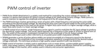
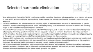
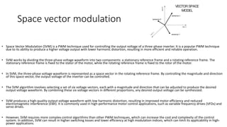
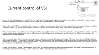
Power Converters for AC
drives
Suvendu Mondal
AP, EED, SurTech
PWM control of inverter
• PWM (Pulse Width Modulation) is a widely used method for controlling the output voltage of inverters. An
inverter is a device that converts DC (direct current) voltage to AC (alternating current) voltage. PWM control is
used in inverters to regulate the amplitude and frequency of the AC output voltage.
• The PWM technique involves generating a series of pulses with a fixed frequency and varying the pulse width
according to the desired output voltage. By adjusting the duty cycle (ratio of pulse width to the pulse period), the
average voltage delivered to the load can be varied. A higher duty cycle results in a higher average voltage, while a
lower duty cycle results in a lower average voltage.
• In PWM control of an inverter, a high-frequency carrier signal is used to modulate the DC input voltage to produce
the desired AC output voltage. The carrier signal typically has a frequency in the range of 10 kHz to several tens of
kHz. The width of the pulses is modulated in proportion to the amplitude of the AC output voltage. The
modulation technique used is often referred to as sinusoidal pulse width modulation (SPWM).
• SPWM generates a series of pulses whose widths are varied sinusoidally at a frequency equal to the desired
output frequency. The amplitude of the sinusoidal modulation waveform is proportional to the desired output
voltage amplitude. This technique produces a high-quality output waveform with low distortion.
• PWM control of inverters is widely used in applications such as motor drives, uninterruptible power supplies
(UPS), solar power systems, and grid-tied inverters. It provides a reliable and efficient method for controlling the
output voltage of the inverter, and is widely used in industry and consumer applications.
Selected harmonic elimination
•
Selected Harmonic Elimination (SHE) is a technique used for controlling the output voltage waveform of an inverter. It is a type
of Pulse Width Modulation (PWM) technique that allows the selective elimination of specific harmonics from the output
waveform.
• The main idea behind SHE is to determine the switching angles of the inverter that will result in the elimination of specific
harmonics in the output voltage waveform. This is achieved by solving a set of nonlinear equations that relate the switching
angles to the desired harmonic content of the waveform.
• The SHE technique has several advantages over other PWM techniques, such as reduced harmonic distortion and improved
efficiency. By eliminating specific harmonics, SHE can reduce the amount of harmonic distortion in the output waveform,
which can reduce the stress on the load and improve system efficiency. In addition, SHE can improve the overall power quality
of the system by reducing the amount of harmonic distortion injected into the power grid.
• However, SHE requires a more complex control algorithm and may be computationally intensive, which can increase the cost
and complexity of the control system. It is also more difficult to implement for non-sinusoidal waveforms, as the equations
that relate the switching angles to the desired harmonic content may become more complex.
• SHE is commonly used in applications such as motor drives, UPS systems, and renewable energy systems where high power
quality is required. It provides a way to control the output waveform with high precision and efficiency, while minimizing the
harmonic distortion and improving the overall power quality of the system.
Space vector modulation
• Space Vector Modulation (SVM) is a PWM technique used for controlling the output voltage of a three-phase inverter. It is a popular PWM technique
due to its ability to produce a higher voltage output with lower harmonic distortion, resulting in more efficient and reliable operation.
• SVM works by dividing the three-phase voltage waveform into two components: a stationary reference frame and a rotating reference frame. The
stationary reference frame is fixed to the stator of the motor, while the rotating reference frame is fixed to the rotor of the motor.
• In SVM, the three-phase voltage waveform is represented as a space vector in the rotating reference frame. By controlling the magnitude and direction
of this space vector, the output voltage of the inverter can be controlled.
• The SVM algorithm involves selecting a set of six voltage vectors, each with a magnitude and direction that can be adjusted to produce the desired
output voltage waveform. By combining these six voltage vectors in different proportions, any desired output voltage can be synthesized.
• SVM produces a high-quality output voltage waveform with low harmonic distortion, resulting in improved motor efficiency and reduced
electromagnetic interference (EMI). It is commonly used in high-performance motor control applications, such as variable frequency drives (VFDs) and
servo drives.
• However, SVM requires more complex control algorithms than other PWM techniques, which can increase the cost and complexity of the control
system. In addition, SVM can result in higher switching losses and lower efficiency at high modulation indices, which can limit its applicability in high-
power applications.
Current control of VSI
• Current control of Voltage Source Inverter (VSI) is an important technique used to regulate the output current of the inverter. VSI is a type of power
electronics device that converts DC voltage into AC voltage with variable frequency and amplitude.
• In current control of VSI, the output current is monitored using a current sensor, and the control system adjusts the inverter output voltage to regulate
the output current. The control system typically consists of a current controller and a pulse width modulation (PWM) generator.
• The current controller uses a reference current signal and the measured current to calculate the error signal. The error signal is then used to adjust the
inverter output voltage to achieve the desired output current. The PWM generator generates the switching signals for the inverter to produce the
required output voltage waveform.
• There are several types of current control techniques used in VSI systems, including Proportional-Integral (PI), Proportional-Resonant (PR), and Model
Predictive Control (MPC). PI control is a simple and commonly used technique that provides good dynamic performance, while PR control offers better
stability and robustness against grid disturbances. MPC is a more advanced control technique that uses a mathematical model of the system to predict
future behavior and optimize the control signals.
• Current control of VSI is used in a wide range of applications, including motor control, renewable energy systems, and power conditioning systems. It
provides precise control of the output current and ensures stable and reliable operation of the system.
Three level inverter
• A three-level inverter is a type of voltage source inverter (VSI) that provides three levels of output voltage, i.e., positive, negative, and zero levels. It is
commonly used in high-power applications where higher voltage and lower harmonic distortion are required.
• In a three-level inverter, the DC voltage is first divided into two equal parts and then fed to two half-bridge inverters. Each half-bridge inverter consists of
two switches, typically insulated gate bipolar transistors (IGBTs) or metal-oxide-semiconductor field-effect transistors (MOSFETs), connected in series
across the DC voltage. The output of each half-bridge inverter is connected to a common point, creating three voltage levels at the output.
• To generate the three voltage levels, the switches in the half-bridge inverters are switched on and off in a specific sequence using a pulse width
modulation (PWM) technique. The PWM technique controls the duty cycle of the switches to produce the desired output voltage waveform.
• The three-level inverter provides several advantages over a traditional two-level inverter. First, it produces a higher output voltage with lower harmonic
distortion, resulting in more efficient and reliable operation. Second, it reduces the voltage stress on the switches, which increases the lifespan of the
inverter. Third, it provides a smoother and more continuous output waveform, which reduces electromagnetic interference (EMI) and improves the
quality of the output signal.
• The three-level inverter is commonly used in applications such as motor drives, renewable energy systems, and grid-tied inverters. It provides a high-
quality output voltage waveform with improved efficiency and reliability, making it a popular choice for high-power applications.
Different topologies
• In power electronics, there are several types of circuit topologies used to convert one form of electrical energy to another. Here are some of the most common topologies used in power electronics:
1. 1. Buck converter: A buck converter is a step-down DC-DC converter that converts a higher voltage DC input to a lower voltage DC output. It uses a switch and an inductor to store and release energy, and
a diode to control the direction of current flow.
2. 2. Boost converter: A boost converter is a step-up DC-DC converter that converts a lower voltage DC input to a higher voltage DC output. It also uses a switch, an inductor, and a diode to store and release
energy, but in a different configuration than the buck converter.
3. 3. Buck-boost converter: A buck-boost converter is a DC-DC converter that can both step up and step down the input voltage to produce the desired output voltage. It uses a combination of the buck and
boost converter topologies to achieve this.
4. 4. Flyback converter: A flyback converter is a type of isolated DC-DC converter that uses a transformer to transfer energy from the input to the output. It uses a switch and an inductor to store energy in
the transformer, and a diode to control the direction of current flow.
5. 5. Full-bridge converter: A full-bridge converter is a type of DC-DC converter that uses four switches arranged in a bridge configuration to convert DC input to DC output. It can operate in both step-up
and step-down modes, and is commonly used in high-power applications.
6. 6. Half-bridge converter: A half-bridge converter is a simpler version of the full-bridge converter, using only two switches. It is used in lower-power applications where the full-bridge converter is not
necessary.
7. 7. Three-phase inverter: A three-phase inverter is a type of circuit that converts DC input to AC output. It is used in three-phase motor drives and other three-phase power applications. It uses six switches
arranged in a bridge configuration to produce the three-phase output.
• These are just a few of the many different circuit topologies used in power electronics. The choice of topology depends on the specific application, performance requirements, and cost considerations.
SVM for 3 level inverter
• Space Vector Modulation (SVM) is a popular technique used to generate pulse width modulation (PWM) signals for three-level
inverters. SVM is a more advanced technique than traditional PWM, which allows for more efficient utilization of the DC
voltage source and reduces the harmonic distortion of the output waveform.
• In SVM for three-level inverters, the reference voltage vector is projected onto the two-dimensional plane of the inverter
output voltage vectors. This projection results in eight possible voltage vectors, including the zero vector. These voltage vectors
are arranged in a hexagon shape in the two-dimensional plane.
• The SVM algorithm calculates the required voltage vector for each sampling interval by comparing the reference voltage vector
with the available voltage vectors in the hexagon. The algorithm selects the two nearest voltage vectors and calculates the
PWM duty cycles of the switches to generate the required output voltage vector.
• To generate the PWM signals, the SVM algorithm first calculates the time interval for each of the two selected voltage vectors
based on the desired output voltage magnitude. It then calculates the PWM duty cycle of each switch in the inverter based on
the time intervals and the selected voltage vectors.
• The SVM technique for three-level inverters offers several advantages over traditional PWM techniques. It reduces the
harmonic distortion of the output waveform, improves the efficiency of the inverter, and provides more precise control of the
output voltage. It is widely used in motor drives, renewable energy systems, and other high-power applications where high-
quality output voltage is essential.
Diode rectifier with boost chopper
• A diode rectifier with a boost chopper is a type of DC-DC converter that combines a diode rectifier with a boost chopper to provide a regulated DC output voltage. This topology is commonly used in
applications such as photovoltaic systems, where a boost converter is needed to raise the voltage of the DC input from a solar panel to a higher level, and a diode rectifier is used to convert the AC output from
the boost converter to a DC output.
• The boost chopper is used to control the output voltage by regulating the duty cycle of the chopper switch. The chopper switch is typically a MOSFET or an IGBT that is turned on and off at a high frequency to
regulate the output voltage. The boost chopper works by storing energy in the inductor when the chopper switch is turned on and releasing it when the switch is turned off.
• The diode rectifier is connected to the output of the boost chopper to convert the AC output to DC. The rectifier consists of diodes that allow current to flow in only one direction, effectively converting the AC
output to a pulsating DC voltage. The output of the rectifier is then filtered with a capacitor to smooth out the DC voltage and reduce ripple.
• The overall operation of the diode rectifier with a boost chopper can be summarized as follows:
• 1. The boost chopper raises the voltage of the DC input from a lower level to a higher level.
• 2. The diode rectifier converts the AC output of the boost chopper to a pulsating DC voltage.
• 3. The output of the rectifier is filtered with a capacitor to smooth out the DC voltage and reduce ripple.
• 4. The duty cycle of the chopper switch is controlled to regulate the output voltage.
• The diode rectifier with a boost chopper provides a regulated DC output voltage that is higher than the input voltage, making it well-suited for applications such as photovoltaic systems and battery charging
circuits. It is an efficient and cost-effective solution for these applications, providing a simple and reliable method of converting DC voltage.
PWM converter as line side rectifier
• A PWM converter can be used as a line side rectifier to convert AC voltage from the grid to a regulated DC voltage. This topology is commonly used in high-power applications such as motor drives, where a
regulated DC voltage is required to power the motor.
• In this configuration, the PWM converter consists of a three-phase bridge rectifier followed by a DC-DC converter. The bridge rectifier converts the AC voltage from the grid to a pulsating DC voltage, which is
then filtered with a capacitor to reduce ripple. The DC-DC converter then regulates the output voltage by controlling the duty cycle of the chopper switch.
• The DC-DC converter in the PWM converter can be implemented using various topologies such as buck, boost, or buck-boost, depending on the requirements of the application. The chopper switch in the DC-
DC converter is typically a MOSFET or an IGBT that is turned on and off at a high frequency to regulate the output voltage.
• The overall operation of the PWM converter as a line side rectifier can be summarized as follows:
• 1. The three-phase bridge rectifier converts the AC voltage from the grid to a pulsating DC voltage.
• 2. The output of the rectifier is filtered with a capacitor to reduce ripple.
• 3. The DC-DC converter regulates the output voltage by controlling the duty cycle of the chopper switch.
• 4. The regulated DC voltage is used to power the load, such as a motor.
• The PWM converter as a line side rectifier offers several advantages over traditional diode rectifiers. It provides a regulated DC output voltage, which is essential for high-power applications such as motor
drives. It also reduces the harmonic distortion of the input current, improves the power factor, and offers better control of the output voltage. However, it is more complex and expensive than a diode rectifier
and requires careful design and control to achieve optimal performance.
Current fed inverters with self-commutated
devices
• Current-fed inverters with self-commutated devices are a type of power electronic converter used in high-power applications such as motor drives, wind and solar energy
systems, and electric vehicles. They are also known as current source inverters (CSI) or current source converters (CSC), and they use self-commutated devices such as
insulated-gate bipolar transistors (IGBTs) or gate turn-off thyristors (GTOs) to control the output current and voltage.
• In a current-fed inverter with self-commutated devices, the input voltage is connected to a DC source through an inductor, which acts as a current source. The self-
commutated devices, such as IGBTs or GTOs, are connected in a bridge configuration, similar to voltage-fed inverters. However, the control scheme is different from voltage-fed
inverters, as the output current is controlled by regulating the input current.
• The operation of a current-fed inverter with self-commutated devices can be divided into two modes: current-controlled mode and voltage-controlled mode.
• In the current-controlled mode, the input current is controlled by varying the duty cycle of the self-commutated devices. This results in a variable output voltage, which is
regulated by a feedback control loop that measures the output voltage and adjusts the duty cycle of the self-commutated devices to maintain a constant output voltage.
• In the voltage-controlled mode, the input current is fixed, and the output voltage is controlled by varying the duty cycle of the self-commutated devices. This mode is typically
used when the output voltage needs to be varied over a wide range, such as in wind and solar energy systems.
• The main advantages of current-fed inverters with self-commutated devices are their ability to handle large DC input voltages and their superior performance under dynamic
conditions. They also offer better fault tolerance and reliability than voltage-fed inverters, as the input current is fixed and less sensitive to changes in the load.
• However, they are more complex and expensive than voltage-fed inverters and require careful design and control to achieve optimal performance.
Control of CSI
• The control of a current source inverter (CSI) involves regulating the input current, which in turn controls the output voltage and frequency. The control strategy for a CSI
typically involves a closed-loop control system that measures the output voltage and adjusts the input current to maintain a constant output voltage and frequency.
• The following are the basic steps involved in the control of a CSI:
• 1. Current Control Loop: The current control loop is responsible for regulating the input current to the CSI. It measures the input current and compares it to a reference current
signal to generate an error signal. The error signal is then processed by a controller, such as a proportional-integral (PI) controller, to generate a control signal that is used to
adjust the duty cycle of the self-commutating devices (IGBTs or GTOs) in the CSI.
• 2. Voltage Control Loop: The voltage control loop is responsible for regulating the output voltage of the CSI. It measures the output voltage and compares it to a reference
voltage signal to generate an error signal. The error signal is then processed by a controller, such as a PI controller, to generate a control signal that is used to adjust the duty
cycle of the self-commutating devices in the CSI.
• 3. Frequency Control Loop: The frequency control loop is responsible for regulating the output frequency of the CSI. It measures the output voltage and compares it to a
reference frequency signal to generate an error signal. The error signal is then processed by a controller, such as a PI controller, to generate a control signal that is used to adjust
the input current to the CSI.
• 4. Modulation: The modulation stage is responsible for generating the gate pulses for the self-commutating devices based on the control signals from the current, voltage, and
frequency control loops. The gate pulses determine the on/off state of the self-commutating devices, which in turn controls the output voltage and frequency of the CSI.
• The control of a CSI is critical for its reliable operation and performance. The control strategy must be carefully designed and implemented to ensure stable operation, fast
response to changes in load and reference signals, and efficient use of the input power. Additionally, advanced control techniques such as predictive control and model
predictive control can be used to further improve the performance of the CSI.
H bridge as a 4-Q drive
• An H bridge is a four-switch configuration that can be used as a 4-quadrant (4-Q) drive for controlling the direction and speed of a motor or other load. The H bridge consists of
four switches, typically power MOSFETs or IGBTs, that are connected in a bridge configuration with the load connected between the two middle points of the bridge.
• In a 4-Q drive using an H bridge, the switches are controlled using pulse width modulation (PWM) to vary the voltage and direction of the output current. By changing the duty
cycle of the PWM signal, the average voltage applied to the load can be varied, allowing for precise control of the output current and speed of the motor.
• The H bridge can operate in four modes, which correspond to the four quadrants of the current-voltage plane:
• 1. Positive voltage, positive current (Q1): In this mode, the upper left and lower right switches are turned on, while the upper right and lower left switches are turned off. This
allows current to flow from the positive supply through the load, producing a positive output voltage and current.
• 2. Negative voltage, positive current (Q2): In this mode, the upper right and lower left switches are turned on, while the upper left and lower right switches are turned off. This
allows current to flow from the negative supply through the load, producing a negative output voltage and positive current.
• 3. Negative voltage, negative current (Q3): In this mode, the upper left and lower right switches are turned off, while the upper right and lower left switches are turned on. This
allows current to flow from the load through the lower left switch and back to the negative supply, producing a negative output voltage and negative current.
• 4. Positive voltage, negative current (Q4): In this mode, the upper right and lower left switches are turned off, while the upper left and lower right switches are turned on. This
allows current to flow from the load through the upper left switch and back to the positive supply, producing a positive output voltage and negative current.
• The ability of an H bridge to operate in all four quadrants makes it ideal for controlling the direction and speed of a motor, as well as for other applications that require bi-
directional power flow.
Power Converters for AC drives CH-1.pptx

Power Converters for AC drives CH-1.pptx

  • 1.
    Power Converters forAC drives Suvendu Mondal AP, EED, SurTech
  • 2.
    PWM control ofinverter • PWM (Pulse Width Modulation) is a widely used method for controlling the output voltage of inverters. An inverter is a device that converts DC (direct current) voltage to AC (alternating current) voltage. PWM control is used in inverters to regulate the amplitude and frequency of the AC output voltage. • The PWM technique involves generating a series of pulses with a fixed frequency and varying the pulse width according to the desired output voltage. By adjusting the duty cycle (ratio of pulse width to the pulse period), the average voltage delivered to the load can be varied. A higher duty cycle results in a higher average voltage, while a lower duty cycle results in a lower average voltage. • In PWM control of an inverter, a high-frequency carrier signal is used to modulate the DC input voltage to produce the desired AC output voltage. The carrier signal typically has a frequency in the range of 10 kHz to several tens of kHz. The width of the pulses is modulated in proportion to the amplitude of the AC output voltage. The modulation technique used is often referred to as sinusoidal pulse width modulation (SPWM). • SPWM generates a series of pulses whose widths are varied sinusoidally at a frequency equal to the desired output frequency. The amplitude of the sinusoidal modulation waveform is proportional to the desired output voltage amplitude. This technique produces a high-quality output waveform with low distortion. • PWM control of inverters is widely used in applications such as motor drives, uninterruptible power supplies (UPS), solar power systems, and grid-tied inverters. It provides a reliable and efficient method for controlling the output voltage of the inverter, and is widely used in industry and consumer applications.
  • 3.
    Selected harmonic elimination • SelectedHarmonic Elimination (SHE) is a technique used for controlling the output voltage waveform of an inverter. It is a type of Pulse Width Modulation (PWM) technique that allows the selective elimination of specific harmonics from the output waveform. • The main idea behind SHE is to determine the switching angles of the inverter that will result in the elimination of specific harmonics in the output voltage waveform. This is achieved by solving a set of nonlinear equations that relate the switching angles to the desired harmonic content of the waveform. • The SHE technique has several advantages over other PWM techniques, such as reduced harmonic distortion and improved efficiency. By eliminating specific harmonics, SHE can reduce the amount of harmonic distortion in the output waveform, which can reduce the stress on the load and improve system efficiency. In addition, SHE can improve the overall power quality of the system by reducing the amount of harmonic distortion injected into the power grid. • However, SHE requires a more complex control algorithm and may be computationally intensive, which can increase the cost and complexity of the control system. It is also more difficult to implement for non-sinusoidal waveforms, as the equations that relate the switching angles to the desired harmonic content may become more complex. • SHE is commonly used in applications such as motor drives, UPS systems, and renewable energy systems where high power quality is required. It provides a way to control the output waveform with high precision and efficiency, while minimizing the harmonic distortion and improving the overall power quality of the system.
  • 4.
    Space vector modulation •Space Vector Modulation (SVM) is a PWM technique used for controlling the output voltage of a three-phase inverter. It is a popular PWM technique due to its ability to produce a higher voltage output with lower harmonic distortion, resulting in more efficient and reliable operation. • SVM works by dividing the three-phase voltage waveform into two components: a stationary reference frame and a rotating reference frame. The stationary reference frame is fixed to the stator of the motor, while the rotating reference frame is fixed to the rotor of the motor. • In SVM, the three-phase voltage waveform is represented as a space vector in the rotating reference frame. By controlling the magnitude and direction of this space vector, the output voltage of the inverter can be controlled. • The SVM algorithm involves selecting a set of six voltage vectors, each with a magnitude and direction that can be adjusted to produce the desired output voltage waveform. By combining these six voltage vectors in different proportions, any desired output voltage can be synthesized. • SVM produces a high-quality output voltage waveform with low harmonic distortion, resulting in improved motor efficiency and reduced electromagnetic interference (EMI). It is commonly used in high-performance motor control applications, such as variable frequency drives (VFDs) and servo drives. • However, SVM requires more complex control algorithms than other PWM techniques, which can increase the cost and complexity of the control system. In addition, SVM can result in higher switching losses and lower efficiency at high modulation indices, which can limit its applicability in high- power applications.
  • 5.
    Current control ofVSI • Current control of Voltage Source Inverter (VSI) is an important technique used to regulate the output current of the inverter. VSI is a type of power electronics device that converts DC voltage into AC voltage with variable frequency and amplitude. • In current control of VSI, the output current is monitored using a current sensor, and the control system adjusts the inverter output voltage to regulate the output current. The control system typically consists of a current controller and a pulse width modulation (PWM) generator. • The current controller uses a reference current signal and the measured current to calculate the error signal. The error signal is then used to adjust the inverter output voltage to achieve the desired output current. The PWM generator generates the switching signals for the inverter to produce the required output voltage waveform. • There are several types of current control techniques used in VSI systems, including Proportional-Integral (PI), Proportional-Resonant (PR), and Model Predictive Control (MPC). PI control is a simple and commonly used technique that provides good dynamic performance, while PR control offers better stability and robustness against grid disturbances. MPC is a more advanced control technique that uses a mathematical model of the system to predict future behavior and optimize the control signals. • Current control of VSI is used in a wide range of applications, including motor control, renewable energy systems, and power conditioning systems. It provides precise control of the output current and ensures stable and reliable operation of the system.
  • 6.
    Three level inverter •A three-level inverter is a type of voltage source inverter (VSI) that provides three levels of output voltage, i.e., positive, negative, and zero levels. It is commonly used in high-power applications where higher voltage and lower harmonic distortion are required. • In a three-level inverter, the DC voltage is first divided into two equal parts and then fed to two half-bridge inverters. Each half-bridge inverter consists of two switches, typically insulated gate bipolar transistors (IGBTs) or metal-oxide-semiconductor field-effect transistors (MOSFETs), connected in series across the DC voltage. The output of each half-bridge inverter is connected to a common point, creating three voltage levels at the output. • To generate the three voltage levels, the switches in the half-bridge inverters are switched on and off in a specific sequence using a pulse width modulation (PWM) technique. The PWM technique controls the duty cycle of the switches to produce the desired output voltage waveform. • The three-level inverter provides several advantages over a traditional two-level inverter. First, it produces a higher output voltage with lower harmonic distortion, resulting in more efficient and reliable operation. Second, it reduces the voltage stress on the switches, which increases the lifespan of the inverter. Third, it provides a smoother and more continuous output waveform, which reduces electromagnetic interference (EMI) and improves the quality of the output signal. • The three-level inverter is commonly used in applications such as motor drives, renewable energy systems, and grid-tied inverters. It provides a high- quality output voltage waveform with improved efficiency and reliability, making it a popular choice for high-power applications.
  • 7.
    Different topologies • Inpower electronics, there are several types of circuit topologies used to convert one form of electrical energy to another. Here are some of the most common topologies used in power electronics: 1. 1. Buck converter: A buck converter is a step-down DC-DC converter that converts a higher voltage DC input to a lower voltage DC output. It uses a switch and an inductor to store and release energy, and a diode to control the direction of current flow. 2. 2. Boost converter: A boost converter is a step-up DC-DC converter that converts a lower voltage DC input to a higher voltage DC output. It also uses a switch, an inductor, and a diode to store and release energy, but in a different configuration than the buck converter. 3. 3. Buck-boost converter: A buck-boost converter is a DC-DC converter that can both step up and step down the input voltage to produce the desired output voltage. It uses a combination of the buck and boost converter topologies to achieve this. 4. 4. Flyback converter: A flyback converter is a type of isolated DC-DC converter that uses a transformer to transfer energy from the input to the output. It uses a switch and an inductor to store energy in the transformer, and a diode to control the direction of current flow. 5. 5. Full-bridge converter: A full-bridge converter is a type of DC-DC converter that uses four switches arranged in a bridge configuration to convert DC input to DC output. It can operate in both step-up and step-down modes, and is commonly used in high-power applications. 6. 6. Half-bridge converter: A half-bridge converter is a simpler version of the full-bridge converter, using only two switches. It is used in lower-power applications where the full-bridge converter is not necessary. 7. 7. Three-phase inverter: A three-phase inverter is a type of circuit that converts DC input to AC output. It is used in three-phase motor drives and other three-phase power applications. It uses six switches arranged in a bridge configuration to produce the three-phase output. • These are just a few of the many different circuit topologies used in power electronics. The choice of topology depends on the specific application, performance requirements, and cost considerations.
  • 8.
    SVM for 3level inverter • Space Vector Modulation (SVM) is a popular technique used to generate pulse width modulation (PWM) signals for three-level inverters. SVM is a more advanced technique than traditional PWM, which allows for more efficient utilization of the DC voltage source and reduces the harmonic distortion of the output waveform. • In SVM for three-level inverters, the reference voltage vector is projected onto the two-dimensional plane of the inverter output voltage vectors. This projection results in eight possible voltage vectors, including the zero vector. These voltage vectors are arranged in a hexagon shape in the two-dimensional plane. • The SVM algorithm calculates the required voltage vector for each sampling interval by comparing the reference voltage vector with the available voltage vectors in the hexagon. The algorithm selects the two nearest voltage vectors and calculates the PWM duty cycles of the switches to generate the required output voltage vector. • To generate the PWM signals, the SVM algorithm first calculates the time interval for each of the two selected voltage vectors based on the desired output voltage magnitude. It then calculates the PWM duty cycle of each switch in the inverter based on the time intervals and the selected voltage vectors. • The SVM technique for three-level inverters offers several advantages over traditional PWM techniques. It reduces the harmonic distortion of the output waveform, improves the efficiency of the inverter, and provides more precise control of the output voltage. It is widely used in motor drives, renewable energy systems, and other high-power applications where high- quality output voltage is essential.
  • 9.
    Diode rectifier withboost chopper • A diode rectifier with a boost chopper is a type of DC-DC converter that combines a diode rectifier with a boost chopper to provide a regulated DC output voltage. This topology is commonly used in applications such as photovoltaic systems, where a boost converter is needed to raise the voltage of the DC input from a solar panel to a higher level, and a diode rectifier is used to convert the AC output from the boost converter to a DC output. • The boost chopper is used to control the output voltage by regulating the duty cycle of the chopper switch. The chopper switch is typically a MOSFET or an IGBT that is turned on and off at a high frequency to regulate the output voltage. The boost chopper works by storing energy in the inductor when the chopper switch is turned on and releasing it when the switch is turned off. • The diode rectifier is connected to the output of the boost chopper to convert the AC output to DC. The rectifier consists of diodes that allow current to flow in only one direction, effectively converting the AC output to a pulsating DC voltage. The output of the rectifier is then filtered with a capacitor to smooth out the DC voltage and reduce ripple. • The overall operation of the diode rectifier with a boost chopper can be summarized as follows: • 1. The boost chopper raises the voltage of the DC input from a lower level to a higher level. • 2. The diode rectifier converts the AC output of the boost chopper to a pulsating DC voltage. • 3. The output of the rectifier is filtered with a capacitor to smooth out the DC voltage and reduce ripple. • 4. The duty cycle of the chopper switch is controlled to regulate the output voltage. • The diode rectifier with a boost chopper provides a regulated DC output voltage that is higher than the input voltage, making it well-suited for applications such as photovoltaic systems and battery charging circuits. It is an efficient and cost-effective solution for these applications, providing a simple and reliable method of converting DC voltage.
  • 10.
    PWM converter asline side rectifier • A PWM converter can be used as a line side rectifier to convert AC voltage from the grid to a regulated DC voltage. This topology is commonly used in high-power applications such as motor drives, where a regulated DC voltage is required to power the motor. • In this configuration, the PWM converter consists of a three-phase bridge rectifier followed by a DC-DC converter. The bridge rectifier converts the AC voltage from the grid to a pulsating DC voltage, which is then filtered with a capacitor to reduce ripple. The DC-DC converter then regulates the output voltage by controlling the duty cycle of the chopper switch. • The DC-DC converter in the PWM converter can be implemented using various topologies such as buck, boost, or buck-boost, depending on the requirements of the application. The chopper switch in the DC- DC converter is typically a MOSFET or an IGBT that is turned on and off at a high frequency to regulate the output voltage. • The overall operation of the PWM converter as a line side rectifier can be summarized as follows: • 1. The three-phase bridge rectifier converts the AC voltage from the grid to a pulsating DC voltage. • 2. The output of the rectifier is filtered with a capacitor to reduce ripple. • 3. The DC-DC converter regulates the output voltage by controlling the duty cycle of the chopper switch. • 4. The regulated DC voltage is used to power the load, such as a motor. • The PWM converter as a line side rectifier offers several advantages over traditional diode rectifiers. It provides a regulated DC output voltage, which is essential for high-power applications such as motor drives. It also reduces the harmonic distortion of the input current, improves the power factor, and offers better control of the output voltage. However, it is more complex and expensive than a diode rectifier and requires careful design and control to achieve optimal performance.
  • 11.
    Current fed inverterswith self-commutated devices • Current-fed inverters with self-commutated devices are a type of power electronic converter used in high-power applications such as motor drives, wind and solar energy systems, and electric vehicles. They are also known as current source inverters (CSI) or current source converters (CSC), and they use self-commutated devices such as insulated-gate bipolar transistors (IGBTs) or gate turn-off thyristors (GTOs) to control the output current and voltage. • In a current-fed inverter with self-commutated devices, the input voltage is connected to a DC source through an inductor, which acts as a current source. The self- commutated devices, such as IGBTs or GTOs, are connected in a bridge configuration, similar to voltage-fed inverters. However, the control scheme is different from voltage-fed inverters, as the output current is controlled by regulating the input current. • The operation of a current-fed inverter with self-commutated devices can be divided into two modes: current-controlled mode and voltage-controlled mode. • In the current-controlled mode, the input current is controlled by varying the duty cycle of the self-commutated devices. This results in a variable output voltage, which is regulated by a feedback control loop that measures the output voltage and adjusts the duty cycle of the self-commutated devices to maintain a constant output voltage. • In the voltage-controlled mode, the input current is fixed, and the output voltage is controlled by varying the duty cycle of the self-commutated devices. This mode is typically used when the output voltage needs to be varied over a wide range, such as in wind and solar energy systems. • The main advantages of current-fed inverters with self-commutated devices are their ability to handle large DC input voltages and their superior performance under dynamic conditions. They also offer better fault tolerance and reliability than voltage-fed inverters, as the input current is fixed and less sensitive to changes in the load. • However, they are more complex and expensive than voltage-fed inverters and require careful design and control to achieve optimal performance.
  • 12.
    Control of CSI •The control of a current source inverter (CSI) involves regulating the input current, which in turn controls the output voltage and frequency. The control strategy for a CSI typically involves a closed-loop control system that measures the output voltage and adjusts the input current to maintain a constant output voltage and frequency. • The following are the basic steps involved in the control of a CSI: • 1. Current Control Loop: The current control loop is responsible for regulating the input current to the CSI. It measures the input current and compares it to a reference current signal to generate an error signal. The error signal is then processed by a controller, such as a proportional-integral (PI) controller, to generate a control signal that is used to adjust the duty cycle of the self-commutating devices (IGBTs or GTOs) in the CSI. • 2. Voltage Control Loop: The voltage control loop is responsible for regulating the output voltage of the CSI. It measures the output voltage and compares it to a reference voltage signal to generate an error signal. The error signal is then processed by a controller, such as a PI controller, to generate a control signal that is used to adjust the duty cycle of the self-commutating devices in the CSI. • 3. Frequency Control Loop: The frequency control loop is responsible for regulating the output frequency of the CSI. It measures the output voltage and compares it to a reference frequency signal to generate an error signal. The error signal is then processed by a controller, such as a PI controller, to generate a control signal that is used to adjust the input current to the CSI. • 4. Modulation: The modulation stage is responsible for generating the gate pulses for the self-commutating devices based on the control signals from the current, voltage, and frequency control loops. The gate pulses determine the on/off state of the self-commutating devices, which in turn controls the output voltage and frequency of the CSI. • The control of a CSI is critical for its reliable operation and performance. The control strategy must be carefully designed and implemented to ensure stable operation, fast response to changes in load and reference signals, and efficient use of the input power. Additionally, advanced control techniques such as predictive control and model predictive control can be used to further improve the performance of the CSI.
  • 13.
    H bridge asa 4-Q drive • An H bridge is a four-switch configuration that can be used as a 4-quadrant (4-Q) drive for controlling the direction and speed of a motor or other load. The H bridge consists of four switches, typically power MOSFETs or IGBTs, that are connected in a bridge configuration with the load connected between the two middle points of the bridge. • In a 4-Q drive using an H bridge, the switches are controlled using pulse width modulation (PWM) to vary the voltage and direction of the output current. By changing the duty cycle of the PWM signal, the average voltage applied to the load can be varied, allowing for precise control of the output current and speed of the motor. • The H bridge can operate in four modes, which correspond to the four quadrants of the current-voltage plane: • 1. Positive voltage, positive current (Q1): In this mode, the upper left and lower right switches are turned on, while the upper right and lower left switches are turned off. This allows current to flow from the positive supply through the load, producing a positive output voltage and current. • 2. Negative voltage, positive current (Q2): In this mode, the upper right and lower left switches are turned on, while the upper left and lower right switches are turned off. This allows current to flow from the negative supply through the load, producing a negative output voltage and positive current. • 3. Negative voltage, negative current (Q3): In this mode, the upper left and lower right switches are turned off, while the upper right and lower left switches are turned on. This allows current to flow from the load through the lower left switch and back to the negative supply, producing a negative output voltage and negative current. • 4. Positive voltage, negative current (Q4): In this mode, the upper right and lower left switches are turned off, while the upper left and lower right switches are turned on. This allows current to flow from the load through the upper left switch and back to the positive supply, producing a positive output voltage and negative current. • The ability of an H bridge to operate in all four quadrants makes it ideal for controlling the direction and speed of a motor, as well as for other applications that require bi- directional power flow.