Protection & switchgear
•Download as PPTX, PDF•
5 likes•3,423 views

This document provides information on a Power System Protection course taught at Vivekanandha College of Engineering for Women. The syllabus covers 5 units: introduction to protection schemes, relay operating principles and characteristics, apparatus protection, theory of circuit interruption, and circuit breakers. It lists textbooks and presents details on each unit, including topics like relay types, transformer/generator/motor protection, arc phenomena, and different circuit breaker types. The last section provides references for textbooks, websites, and presentations on related topics.

Recommended
More Related Content
What's hot
What's hot (20)
Similar to Protection & switchgear
Similar to Protection & switchgear (20)
More from johny renoald
More from johny renoald (20)
Recently uploaded
Recently uploaded (20)
Protection & switchgear
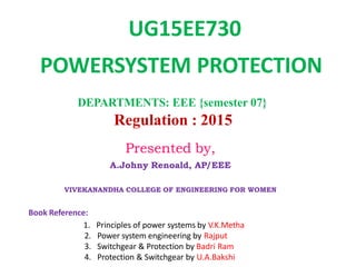
- 1. DEPARTMENTS: EEE {semester 07} Regulation : 2015 Book Reference: 1. Principles of power systems by V.K.Metha 2. Power system engineering by Rajput 3. Switchgear & Protection by Badri Ram 4. Protection & Switchgear by U.A.Bakshi UG15EE730 POWERSYSTEM PROTECTION Presented by, A.Johny Renoald, AP/EEE VIVEKANANDHA COLLEGE OF ENGINEERING FOR WOMEN
- 2. UG15EE730 POWERSYSTEM PROTECTION Syllabus UNIT I INTRODUCTION 9 Importance of protective schemes for electrical apparatus and power system. Qualitative review of faults and fault currents - relay terminology – definitions -and essential qualities of protection. Protection against over voltages due to lightning and switching - arcing grounds - Peterson Coil - ground wires – surge absorber and diverters Power System earthing – neutral Earthing - basic ideas of insulation coordination. UNIT II OPERATING PRINCIPLES AND RELAY CHARACTERISTICS 9 Electromagnetic relays – over current, directional and non directional, distance, negative sequence, differential and under frequency relays – Introduction to static relays.
- 3. UNIT III APPARATUS PROTECTION 9 Main considerations in apparatus protection - transformer, generator and motor protection - protection of bus bars. Transmission line protection - zones of protection. CTs and PTs and their applications in protection schemes. UNIT IV THEORY OF CIRCUIT INTERRUPTION 9 Physics of arc phenomena and arc interruption. DC and AC circuit breaking - restriking voltage and recovery voltage - rate of rise of recovery voltage - resistance switching - current chopping - interruption of capacitive current. UNIT V CIRCUIT BREAKERS 9 Types of circuit breakers – air blast, air break, oil, SF6 and vacuum circuit breakers – comparative merits of different circuit breakers – testing of circuit breakers.
- 5. UNIT 5 Syllabus Types of circuit breakers 1. Air Blast circuitbreaker 2. Vacuum circuit breaker 3. Oil circuit breaker 4. SF6 circuitbreaker Comparison of Airblast,Vacuum,Oil,SF6 Testing of circuit breakers.
- 6. Types Of Circuit Breakers Oil Circuit Breakers Vacuum Circuit Breakers Air Blast Circuit Breakers SF6 Circuit Breakers Presented by C.GOKUL,AP/EEE ,Velalar College of Engg & Tech , Erode
- 7. 1. OIL CIRCUIT BREAKER It is designed for 11kv-765kv. These are of two types • BOCB (Bulk oil Circuit Breaker) • MOCB (Minimum oil Circuit Breaker) The contacts are immersed in oil bath. Oil provides cooling by hydrogen created by arc. It acts as a good dielectric medium and quenches the arc.
- 8. Advantages: Oil has good dielectric strength. Low cost. Oil is easily available. It has wide range of breaking capability. Disadvantages: Slower operation , takes about 20 cycles for arc quenching. It is highly inflammable , so high risk of fire. High maintenance cost.
- 9. 2. VACCUM CIRCUIT BREAKER It is designed for medium voltage range (3.3-33kv). This consists of vacuum of pressure (1*10-6) inside arc extinction chamber. The arc burns in metal vapour when the contacts are disconnected. At high voltage , it’s rate of dielectric strength recovery is very high. Due to vacuum arc extinction is very fast. The contacts loose metals gradually due to formation of metal vapours.
- 10. Advantages: Free from arc and fire hazards. Low cost for maintenance & simpler mechanism. Low arcing time & high contact life. Silent and less vibrational operation. Due to vacuum contacts remain free from corrosion. No byproducts formed. Disadvantages: High initial cost due to creation of vacuum. Surface of contacts are depleted due to metal vapours. High cost & size required for high voltage breakers.
- 11. 3. AIR BLAST CIRCUIT BREAKERS This operates using high velocity blast of air which quenches the arc. It consists of blast valve , blast tube & contacts. Blast valve contains air at high pressure. Blast tube carries the air at high pressure & opens the moving contact attached to spring. There is no carbonization of surface as in VCB. Air should be kept clean & dry to operate it properly.
- 13. Advantages: High speed operation as compared to OCB. Ability to withstand frequent switching. Facility for high speed reclosure. Less maintenance as compared to OCB. Disadvantages: Little moisture content prolongs arcing time. Pressure should be checked frequently for frequent operation. Risk of fire hazards due to over voltages. It can’t be used for high voltage operation due to prolonged arc quenching.
- 14. 4. SF6 CIRCUIT BREAKERS It contains an arc interruption chamber containing SF6 gas. In closed position the contacts remain surrounded by SF6 gas at a pressure of 2.8 kg/cm2 . During opening high pressure SF6 gas at 14 kg/cm2 from its reservoir flows towards the chamber by valve mechanism. SF6 rapidly absorbs the free electrons in the arc path to form immobile negative ions to build up high dielectric strength. It also cools the arc and extinguishes it. After operation the valve is closed by the action of a set of springs. Absorbent materials are used to absorb the byproducts and moisture.
- 15. Presented by C.GOKUL,AP/EEE ,Velalar College of Engg & Tech , Erode
- 16. Advantages: Very short arcing period due to superior arc quenching property of SF6 . Can interrupt much larger currents as compared to other breakers. No risk of fire. Low maintenance, light foundation. No over voltage problem. There are no carbon deposits. Disadvantages: SF6 breakers are costly due to high cost of SF6. SF6 gas has to be reconditioned after every operation of the breaker, additional equipment is required for this purpose.
- 17. Comparison of Circuit Breakers
- 18. CONCLUSION: Therefore, we conclude that circuit breaker is the most essential part of the electrical networks as it protects every device from damage. It helps us to detect the fault and area affected by it. Nowadays vacuum and SF6 circuit breakers are widely used due to their reliable and fast operations. Presented by C.GOKUL,AP/EEE ,Velalar College of Engg & Tech , Erode
- 20. Why "Testing of Circuit Breaker" is Necessary? A Circuit Breaker should be capable of carrying, making, and breaking under normal and abnormal conditions. In any power system circuit breaker has to withstand power frequency over voltages and transient over voltages due to switching and lightning. The performance of a circuit breaker under normal and abnormal conditions can be verified by performing different type of tests on circuit breakers. The main purpose of testing of circuit breakers is to confirm if circuit breaker is able to work on particular voltage and current ratings or not.
- 21. There are mainly two tests classified: 1) Type test 2) Routine Test 1) Type Tests: The purpose of type tests is to prove design features and the quality of circuit breaker. Type tests are not conducted on each circuit breaker. This is done to prove the capabilities and to confirm the rated characteristics of the circuit breakers.
- 22. 2)Routine Tests: Routine test is performed before circuit breaker dispatch to ensure the product. This gives result about defects in materials and construction of circuit breaker. We can check quality of material of circuit breaker by performing Routine Test.
- 23. Mechanical endurance tests Thermal tests Dielectric tests Measurement of resistance of the main circuits Short Circuit tests
- 24. In this test, the C.B.. is open and closed 500 times or other value as agreed to between the purchaser and the supplier.the test are carried out without current through the main circuit of the C.B.Out of the total number of tests, 10% should be closed-open operation,that is with the tripping,mechanism energized by the closing of main contacts.During the tests,occasional lubrication,but no mechanical adjustments are permissible.after the tests,all parts including contacts should be in good condition and there should be no permanent distortion and undue wear of the parts.
- 25. This test determines the maximum normal current that the circuit breaker can carry without exceeding the maximum allowable temperature rise.In this test the rated normal current of normal frequency is passed through the current carrying parts of circuit breaker. Method are recognized by Indian standards for measuring temperature rise of parts:- 1) Thermometer method 2) Thermocouple method 3) Self resistance method
- 26. 1) Breaking capacity Test:- • Sequence of performing this tests is as follows:- First of all,the master circuit breaker (MB)and the breaker under test (TB)are closed. The s.c.current is passed by closing the make switch. The circuit breaker under test(TB) is opened to interrupt the s.c.currentat desired moment. • The following measurements related to the breaking capacity performance are taken from the oscillogram during the test:- Symmetrical breaking current Asymmetrical breaking current Amplitude factor Natural frequency of oscillations and RRRV(RATE OF RISE OF RISTRIKING VOLTAGE)
- 27. Sequence of Performing this test :- First of all,the master circuit breaker (MB)and the make switch(MS) are closed. Then,the short circuit current is initiated by closing the test breaker (TB). The rated short circuit making current i.e.the peak value of the first major loop of the short circuit current envelope is measured from the oscillorgram.
- 28. 3) Short Time Withstand Current Capacity •In this test, the rated short-time withstand current is applied to the circuit breaker under test for the specified duration of the time. •The rated short time withstand current is equal to be rated short circuit breaking current and standard value of rated duration of short circuit current is 1 second or 3 seconds. •The current is measured by taking an oscillograph of the short circuit current wave. After the test, there should be no mechanical or insulation damage and any contact welding.
- 29. REFERENCES Presented by C.GOKUL,AP/EEE ,Velalar College of Engg & Tech , Erode
- 30. Book References: Principles of power systems by V.K.Metha Switchgear & Protection by Badri Ram M.L. Soni, P.V. Gupta, V.S. Bhatnagar, A. Chakrabarti, ‘A Text Book on Power System Engineering’ R.K.Rajput, A Tex book of Power System Engineering. Laxmi Publications Protection & Switchgear by U.A.Bakshi Sunil S. Rao, ‘Switchgear and Protection’,Khanna publishers. C.L. Wadhwa, ‘Electrical Power Systems’, Newage International (P) Ltd.
- 31. NPTEL References: Power System Protection by S.A.Soman Department of Electrical Engineering IIT Bombay
- 32. Website References • www.scribd.com • www.slideshare.net • http://www.electrical4u.com/arc- interruption-theory/ • https://iiteeeestudents.wordpress.com/201 2/02/22/the-arc-phenomena-arc-extinction- method-of-arc-extinction/ • http://www.slideshare.net/binitd4/relay- and-switchgear-protection
- 33. Website References • http://www.ece.uidaho.edu/ee/power/ECE525/ • http://www.electrical4u.com/electrical-switchgear- protection/ • https://en.wikipedia.org/ • http://www.polytechnichub.com/problems-of-circuit- interruption/ • http://www.amazon.com/Circuit-Interruption- Theory-Techniques-Thomas/dp/082477177X • http://www.slideshare.net/makadelhi/magnetic- materials
- 34. Website References • http://www.slideshare.net/Sciencetutors/magnets- and-magnetic-materials-presentation • https://electricalnotes.wordpress.com/2012/01/21/t ypes-of-neutral-earthing-in-power-distribution/ • http://www.electrical4u.com/electromagnetic-relay- working-types-of-electromagnetic-relays/ • http://www.electrical4u.com/arc-interruption-theory/
- 35. PPT References: “POWER SYSTEM PROTECTIVE RELAYING” by Engr. Ulysses Paguio(P.E.E.) BSEE79/MIT&BSECE80MIT RAMU SRIKAKULAPU,ASSISTANT PROFESSOR , SHARDA UNIVERSITY Protection Fundamentals by Craig Wester , John Levine EE – 6204, Power System Protection Power System Protection Fundamentals by SELUniversity
- 36. PPT References Unit 1: Power System Protection Fundamentals by Dr. Youssef A. Mobarak PROTECTION & RELAY SCHEMES Earthing by Er. Satnam Singh Lecturer(Electrical engg.) GPCMohali (Khunimajra) ET 601 – POWER SYSTEM PROTECTION POWER SYSTEM PROTECTION by Chandra Bhushan Singh EE 445 Course Presentation Power System Protection by Mohammed AL-Zeer SURGE DIVERTER by NEHA KARDAM & FARHEEN KHAN INTRODUCTION TO SWITCHGEAR by R.J.Phansalkar Symmetrical Components I by Dave Angell Idaho Power
- 37. PPT References Unit 2: TRANSFORMER PROTECTIONS by S.Balamurugan Introduction to Protection Relay byIr.S.Gopinath Protective Relays by Dr.Latif Shaikh GOVERNMENT COLLEGE OF ENGG.,CHANDRAPUR PROTECTIVE RELAY Electrical Relays by Ben Oman Protection and Relay Schemesby Chris Fraser & Amanda Chen Wang Protective Relay by Bhagawan Prasad,Chartered Engineer
- 38. PPT References Unit 3: Motor Protection Principles TRANSFORMER PROTECTION GENERATOR, TRANSFORMER, MOTOR AND TRANSMISSIONLINE PROTECTION PROTECTIONS GENERATOR PROTECTION by ABU SAMAH ABU HASAN,INSTITUT LATIHAN SULTAN AHMAD SHAH,TENAGA NASIONAL BERHAD MALAYSIA Protection of Transmission Lines by Rohini Haridas Generator Protection & Switchgear by Bhushan Kumbhalkar Fundamentals of Transformer Protection by Bhuvanesh Oza Transformer protection ELE304 TRANSFORMER PROTECTION - USAID MOTOR PROTECTION by R.J. Phansalkar R&D , C&S Electric
- 39. PPT References Unit 4: interruption of capacitive current by A.JananiEEE,SREC Dc circuit breaking by A.JananiEEE,SREC PRESENTATION ON CIRCUIT BREAKER Er. by Rahul Sharma CIRCUIT BREAKERS by AUROSISH PANI , Electronicsand Electrical Engineering,7th Sem. ,Roll no-0745
- 40. PPT References Unit 5: CIRCUIT BREAKER by RAVIVARMA A/L AMANATHAN 18746 PCS CIRCUIT BREAKERS Testing of circuit breakers