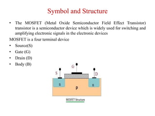
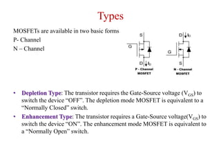
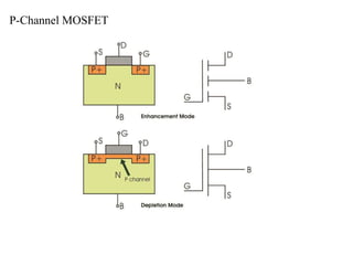
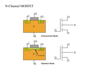
Power MOSFET
Prepared by,
Mr. A. Johny Renoald M.E., Ph.D.,
Symbol and Structure
• The MOSFET (Metal Oxide Semiconductor Field Effect Transistor)
transistor is a semiconductor device which is widely used for switching and
amplifying electronic signals in the electronic devices
MOSFET is a four terminal device
• Source(S)
• Gate (G)
• Drain (D)
• Body (B)
Types
MOSFETs are available in two basic forms
P- Channel
N – Channel
• Depletion Type: The transistor requires the Gate-Source voltage (VGS) to
switch the device “OFF”. The depletion mode MOSFET is equivalent to a
“Normally Closed” switch.
• Enhancement Type: The transistor requires a Gate-Source voltage(VGS) to
switch the device “ON”. The enhancement mode MOSFET is equivalent to
a “Normally Open” switch.
P-Channel MOSFET
N-Channel MOSFET
MOSFET Characteristics
• MOSFETs are tri-terminal, unipolar, voltage-controlled device which form an
integral part of vast variety of electronic circuits.
• These devices can be classified into two types
Depletion-type
Enhancement-type
MOSFET exhibits three operating regions
Cut-Off Region
• Cut-off region is a region in which the MOSFET will be OFF as there will be no
current flow through it.
• In this region, MOSFET behaves like an open switch and is thus used when they
are required to function as electronic switches
Ohmic or Linear Region
• Ohmic or linear region is a region where in the current IDS increases with an
increase in the value of VDS.
• When MOSFETs are made to operate in this region, they can be used as amplifiers.
Saturation Region
• In saturation region device will act like a closed switch through which a
saturated value of IDS flows.
• As a result, this operating region is chosen whenever MOSFETs are
required to perform switching operations
• Transfer characteristics (drain-to-source current IDS versus gate-to-source
voltage VGS) of n-channel Enhancement-type MOSFET
• Current through the device will be zero until the VGS exceeds the value of
threshold voltage VT
• Under this condition, even an increase in VDS will result in no current flow
• Once VGS crosses VT, the current through the device increases with an
increase in IDS initially (Ohmic region) and then saturates to a value as
determined by the VGS (saturation region of operation)
Thank you

Power MOSFET

  • 1.
    Power MOSFET Prepared by, Mr.A. Johny Renoald M.E., Ph.D.,
  • 2.
    Symbol and Structure •The MOSFET (Metal Oxide Semiconductor Field Effect Transistor) transistor is a semiconductor device which is widely used for switching and amplifying electronic signals in the electronic devices MOSFET is a four terminal device • Source(S) • Gate (G) • Drain (D) • Body (B)
  • 3.
    Types MOSFETs are availablein two basic forms P- Channel N – Channel • Depletion Type: The transistor requires the Gate-Source voltage (VGS) to switch the device “OFF”. The depletion mode MOSFET is equivalent to a “Normally Closed” switch. • Enhancement Type: The transistor requires a Gate-Source voltage(VGS) to switch the device “ON”. The enhancement mode MOSFET is equivalent to a “Normally Open” switch.
  • 4.
  • 5.
  • 6.
    MOSFET Characteristics • MOSFETsare tri-terminal, unipolar, voltage-controlled device which form an integral part of vast variety of electronic circuits. • These devices can be classified into two types Depletion-type Enhancement-type MOSFET exhibits three operating regions Cut-Off Region • Cut-off region is a region in which the MOSFET will be OFF as there will be no current flow through it. • In this region, MOSFET behaves like an open switch and is thus used when they are required to function as electronic switches Ohmic or Linear Region • Ohmic or linear region is a region where in the current IDS increases with an increase in the value of VDS. • When MOSFETs are made to operate in this region, they can be used as amplifiers.
  • 7.
    Saturation Region • Insaturation region device will act like a closed switch through which a saturated value of IDS flows. • As a result, this operating region is chosen whenever MOSFETs are required to perform switching operations
  • 8.
    • Transfer characteristics(drain-to-source current IDS versus gate-to-source voltage VGS) of n-channel Enhancement-type MOSFET • Current through the device will be zero until the VGS exceeds the value of threshold voltage VT • Under this condition, even an increase in VDS will result in no current flow • Once VGS crosses VT, the current through the device increases with an increase in IDS initially (Ohmic region) and then saturates to a value as determined by the VGS (saturation region of operation)
  • 9.