Downloaded 168 times

![The explicit expressions of and can be easily calculated
evaluating the following dot products:
(8)
(9)
(10)
(11)
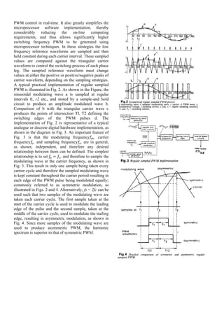
Once and have been calculated, the designer can
still choose in which proportion the two zero vectors are
used to fill the switching period. Fig. 8 shows the vector
sequence corresponding to the example of Fig. 7. In the
sequence of Fig. 3, the zero vectors are equally
distributed in the switching period.
6. Hysteresis Pulse Width Modulation
Hysteresis PWM refers to the technique where the
output is allowed to oscillate within a predefined error
band, called "hysteresis band". The switching instants in
this case are generated from the vertices of the triangular
wave shown in Fig. 9. Hysteresis PWM techniques does
not require any information about the inverter load
characteristics. As long as the reference signal is known
and the inverter output voltage is not saturated, the
inverter output will always follow the reference.
However, the switching frequency of power devices is
not fixed for this technique and will vary depending on
the magnitude and frequency of the reference,. Therefore,
switching losses for this techniques can be higher
compared to other techniques.
IV CONCLUSION
In this term paper pulse width modulation inverter
techniques has been presented. Through various
modulation techniques a general hierarchical consensus
appears to have emerged from this work which ranks
space vector modulation techniques, regular sampled
modulation and sine-triangle modulation strategies in
decreasing order of merit based on harmonics
performance
V. REFRENCES
[1] Lega, A.; Mengoni, M.; Serra, G.; Tani, A.; Zarri, L.,
"General theory of space vector modulation for five-phase
inverters," Industrial Electronics, 2008. ISIE 2008. IEEE
International Symposium on , vol., no., pp.237,244, June 30
2008-July 2 2008
[2] Holtz, J., "Pulsewidth modulation-a survey," Power
Electronics Specialists Conference, 1992. PESC '92 Record.,
23rd Annual IEEE , vol., no., pp.11,18 vol.1, 29 Jun-3 Jul
1992
[3] Bowes, S.R.; Lai, Y.S., "Investigation into optimising high
switching frequency regular sampled PWM control for drives
and static power converters," Electric Power Applications,
IEE Proceedings - , vol.143, no.4, pp.281,293, Jul 1996
[4] Sanakhan, S.; Babaei, E.; Akbari, M.E., "Dynamic
investigation of capacitors voltage of flying capacitor
multilevel inverter based on sine-sawtooth PSCPWM," Power
Electronics, Drive Systems and Technologies Conference
(PEDSTC), 2013 4th , vol., no., pp.182,187, 13-14 Feb. 2013
[5] Zhenyu Yu; Mohammed, A.; Panahi, I., "A review of three
PWM techniques," American Control Conference, 1997.
Proceedings of the 1997 , vol.1, no., pp.257,261 vol.1, 4-6 Jun
1997
[6] Hirota, A.; Nagai, S.; Nakaoka, M., "A novel delta-sigma
modulated DC-DC power converter operating under DC ripple
voltage," Industrial Electronics Society, 1999. IECON '99
Proceedings. The 25th Annual Conference of the IEEE , vol.1,
no., pp.180,184 vol.1, 1999
[7]Holmes,D.G. and Lipo , T.A.
"Pulse Width Modulation for Power Converters:Principles and
Practice "](https://image.slidesharecdn.com/termpaper1-140409124428-phpapp02/85/pulse-width-modulated-inverter-techniques-5-320.jpg)

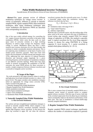
This document provides an overview of various pulse width modulation techniques for voltage source inverters, including naturally sampled PWM, regular sampled PWM, delta modulation, delta sigma modulation, space vector modulation, and hysteresis PWM. It describes the basic concepts and operating principles of each technique, and compares them in terms of performance metrics like harmonic distortion and switching losses. Space vector modulation techniques are ranked as providing the best performance in terms of minimizing harmonics, followed by regular sampled PWM and sine-triangle modulation.