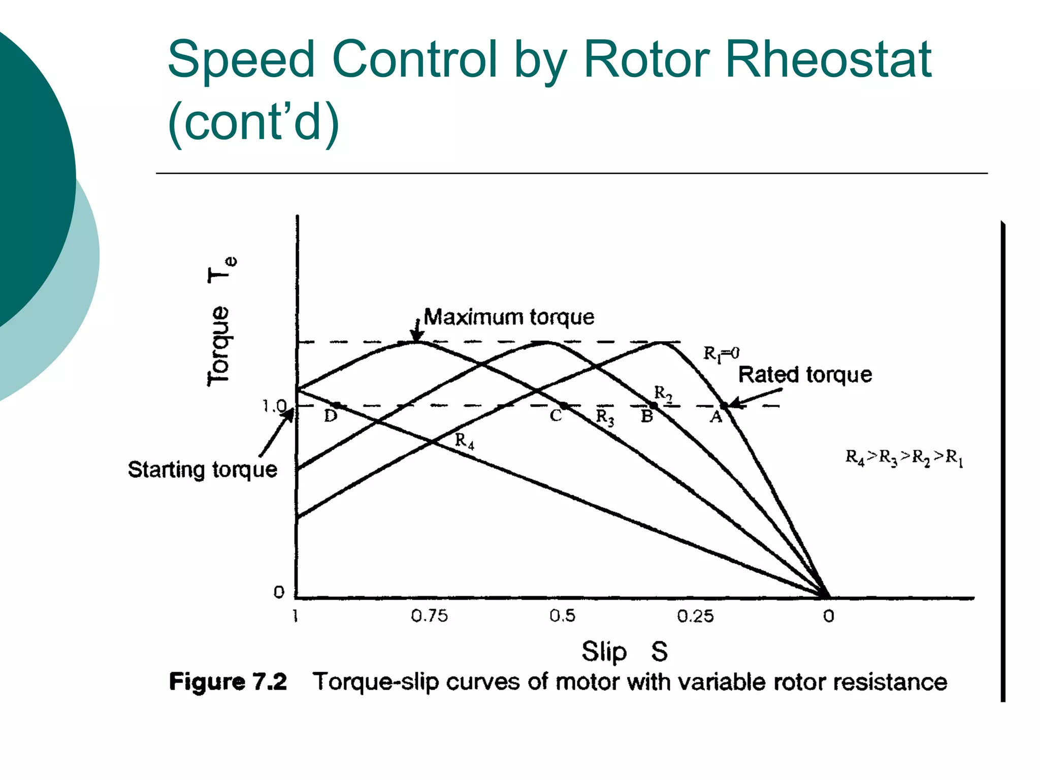
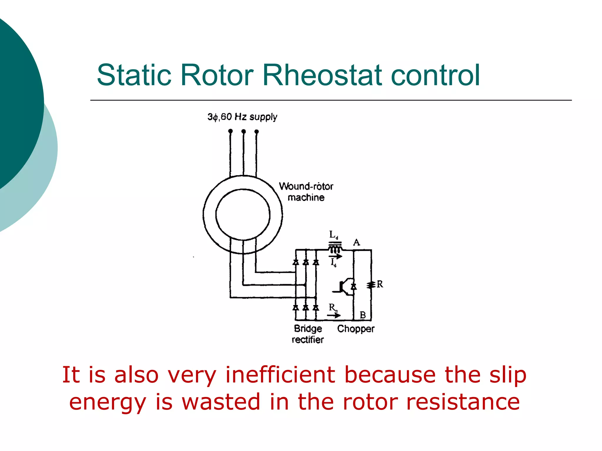
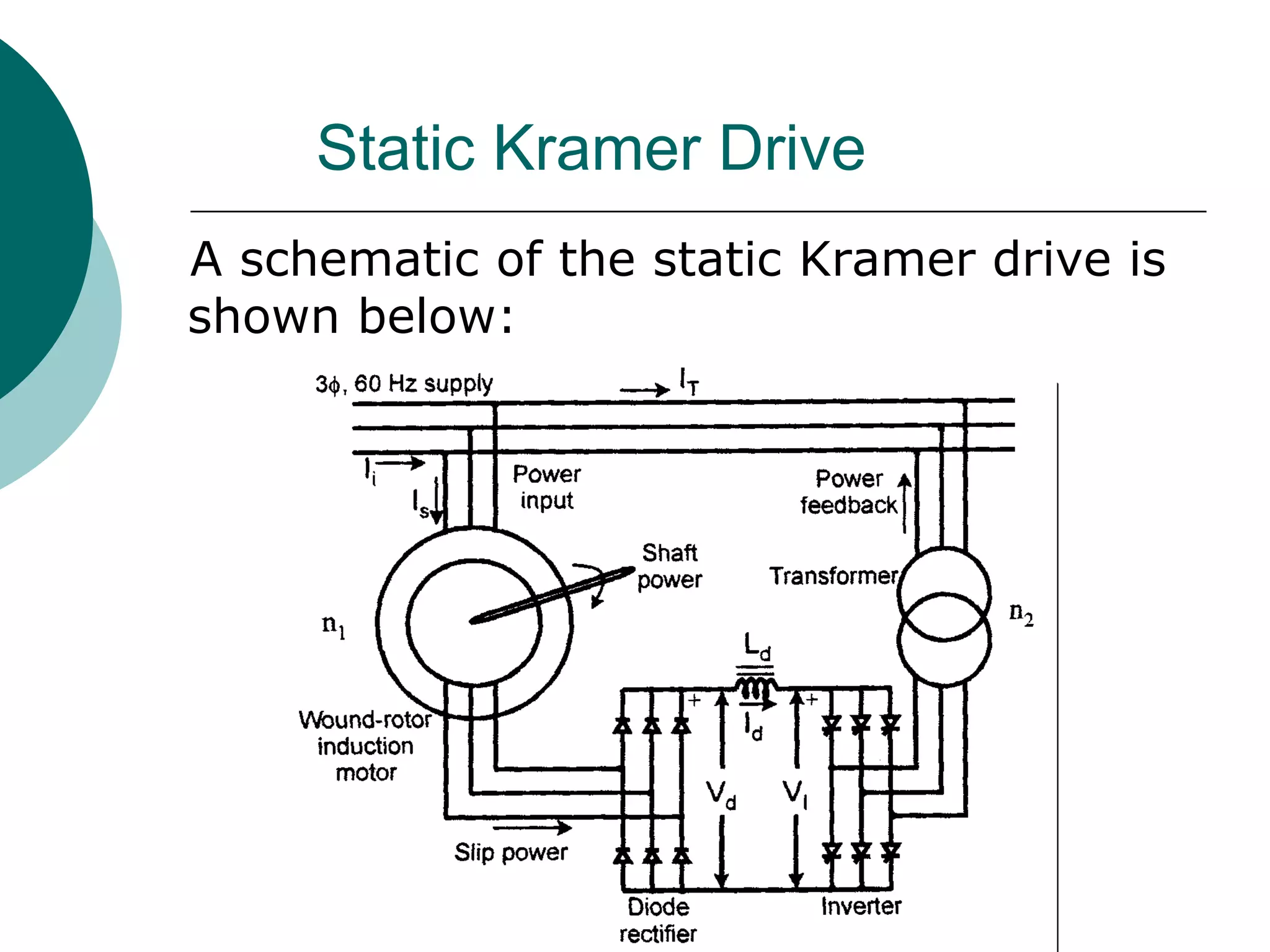
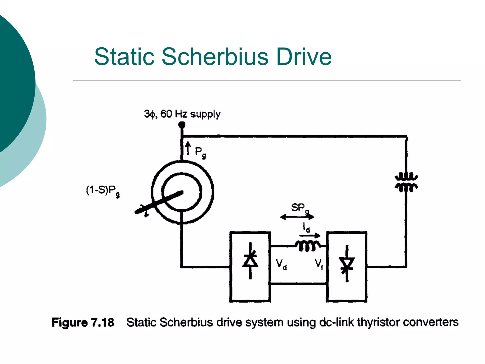
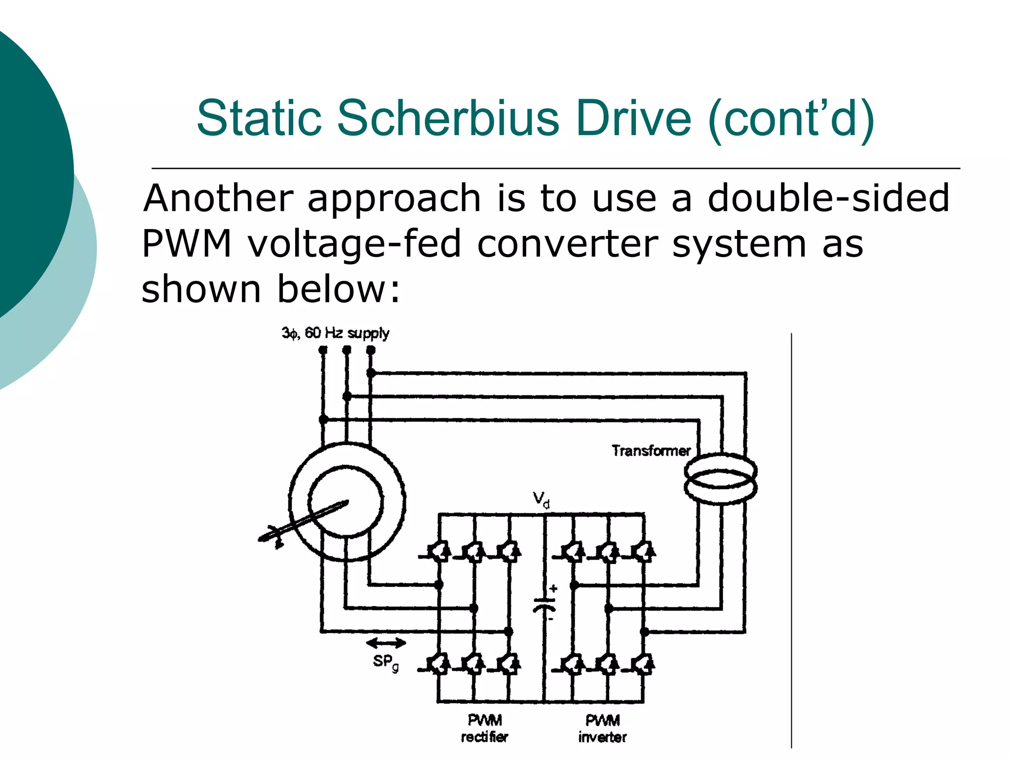
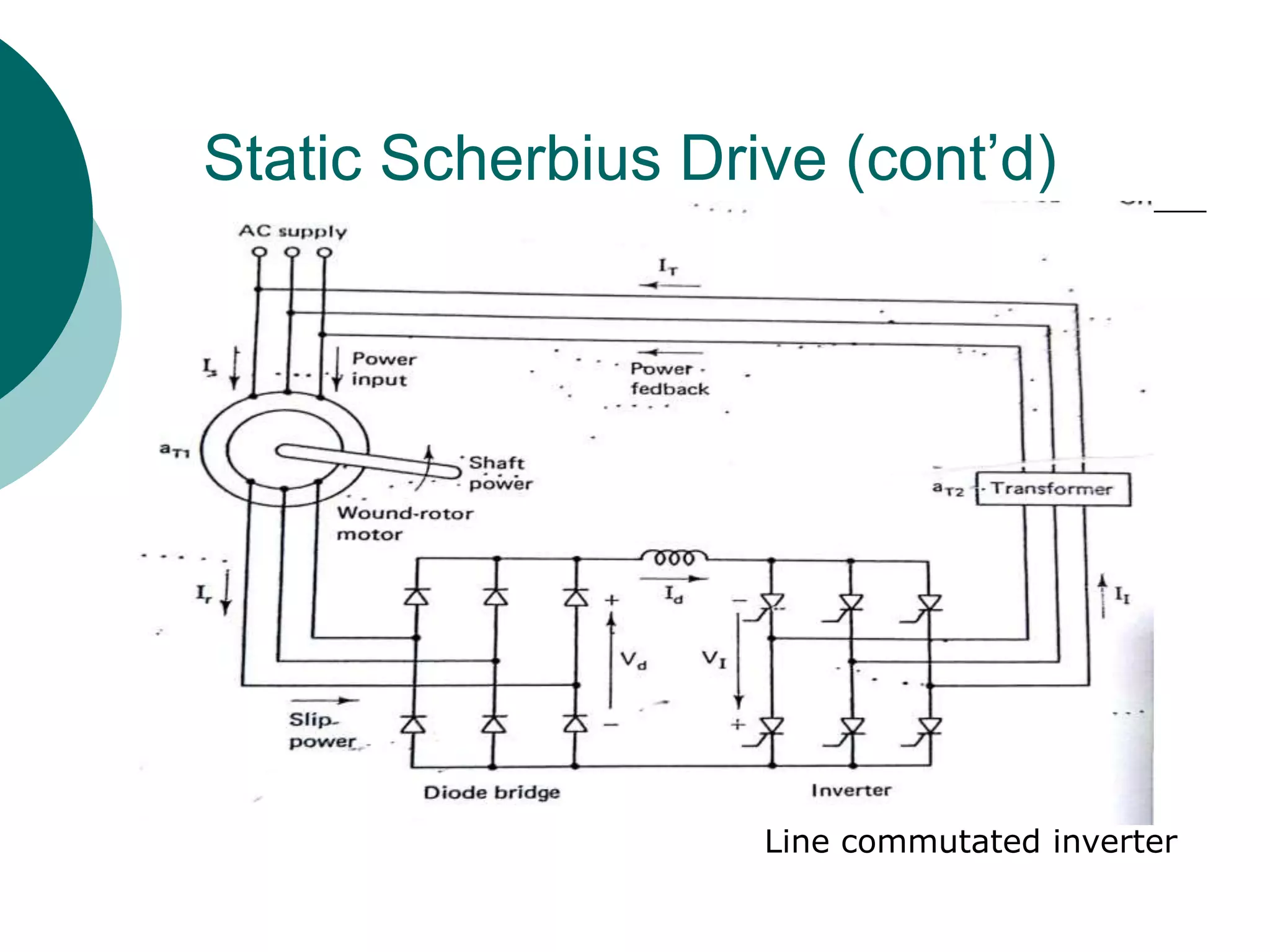
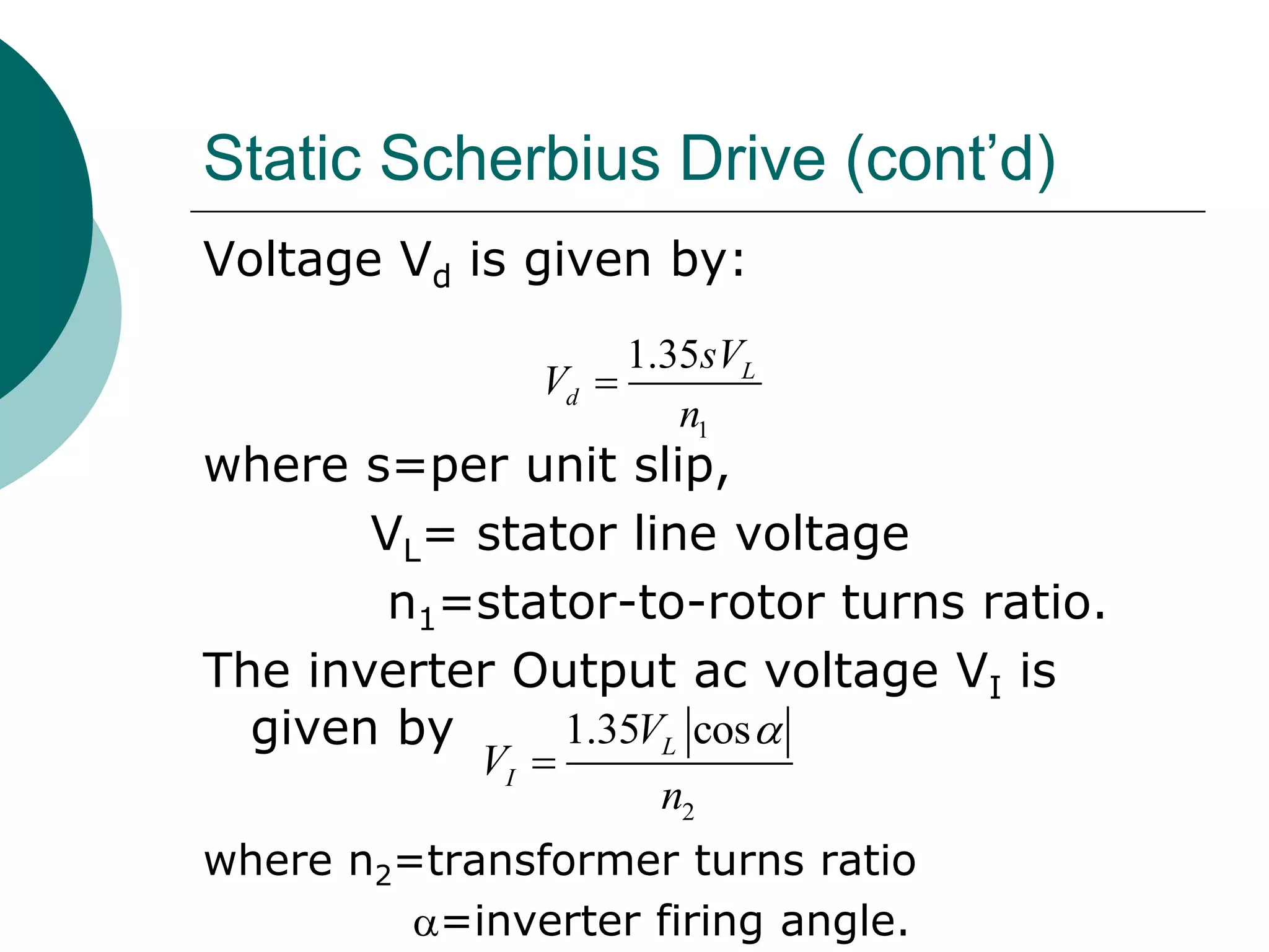
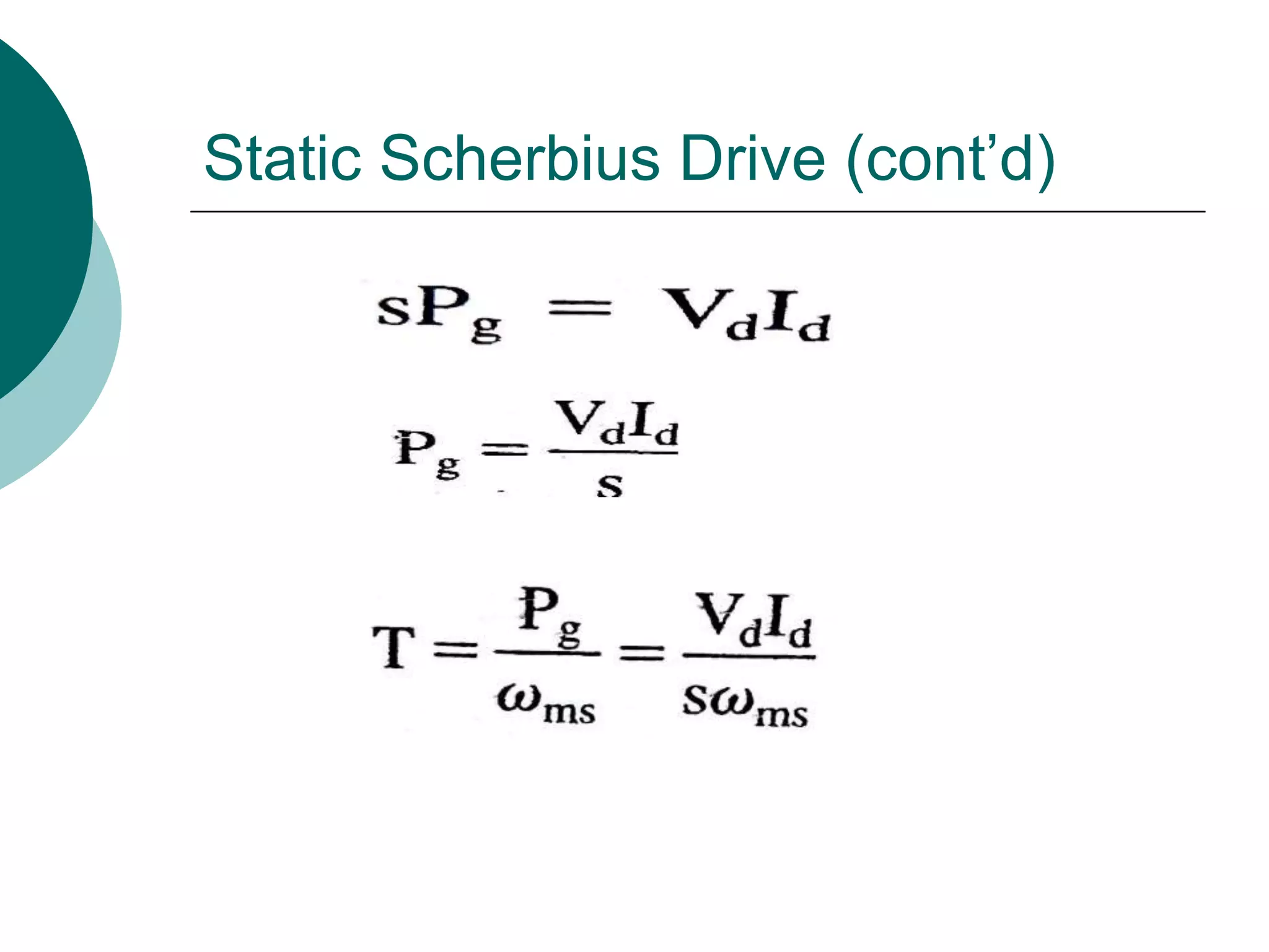
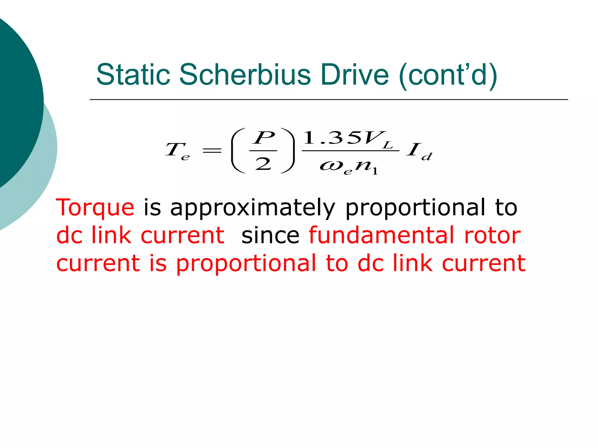
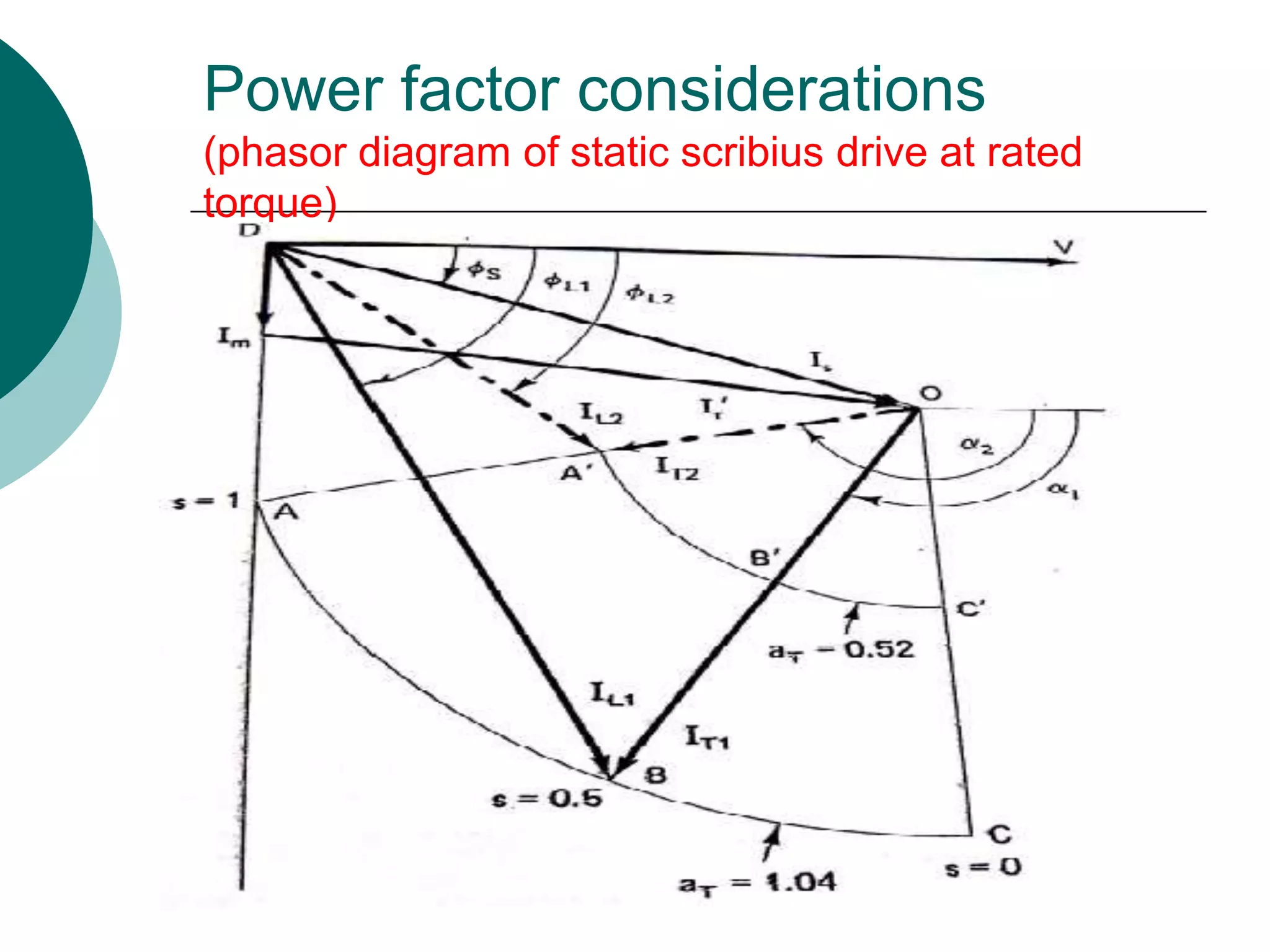
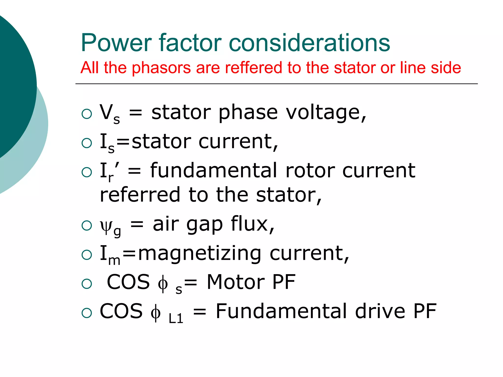
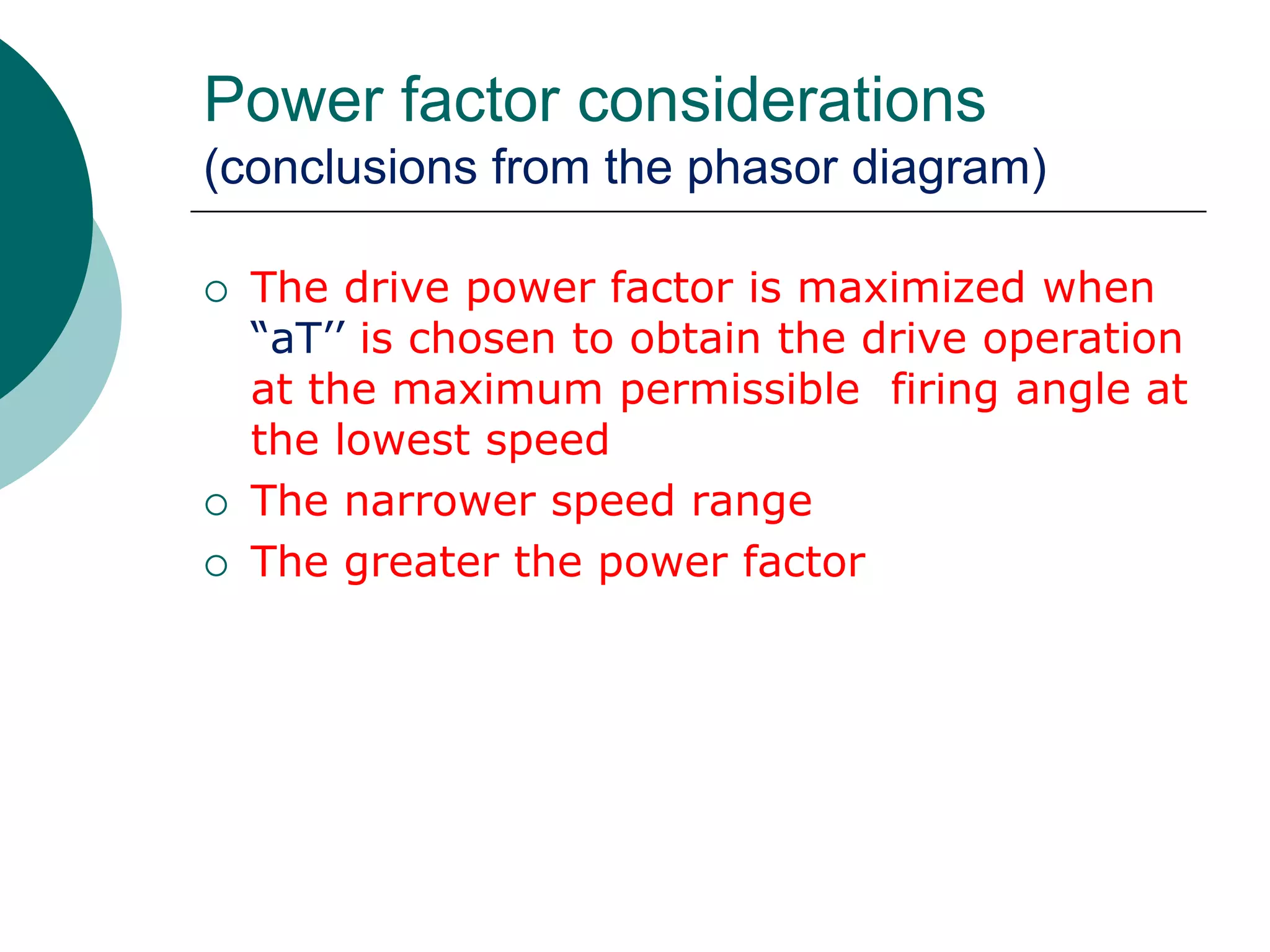
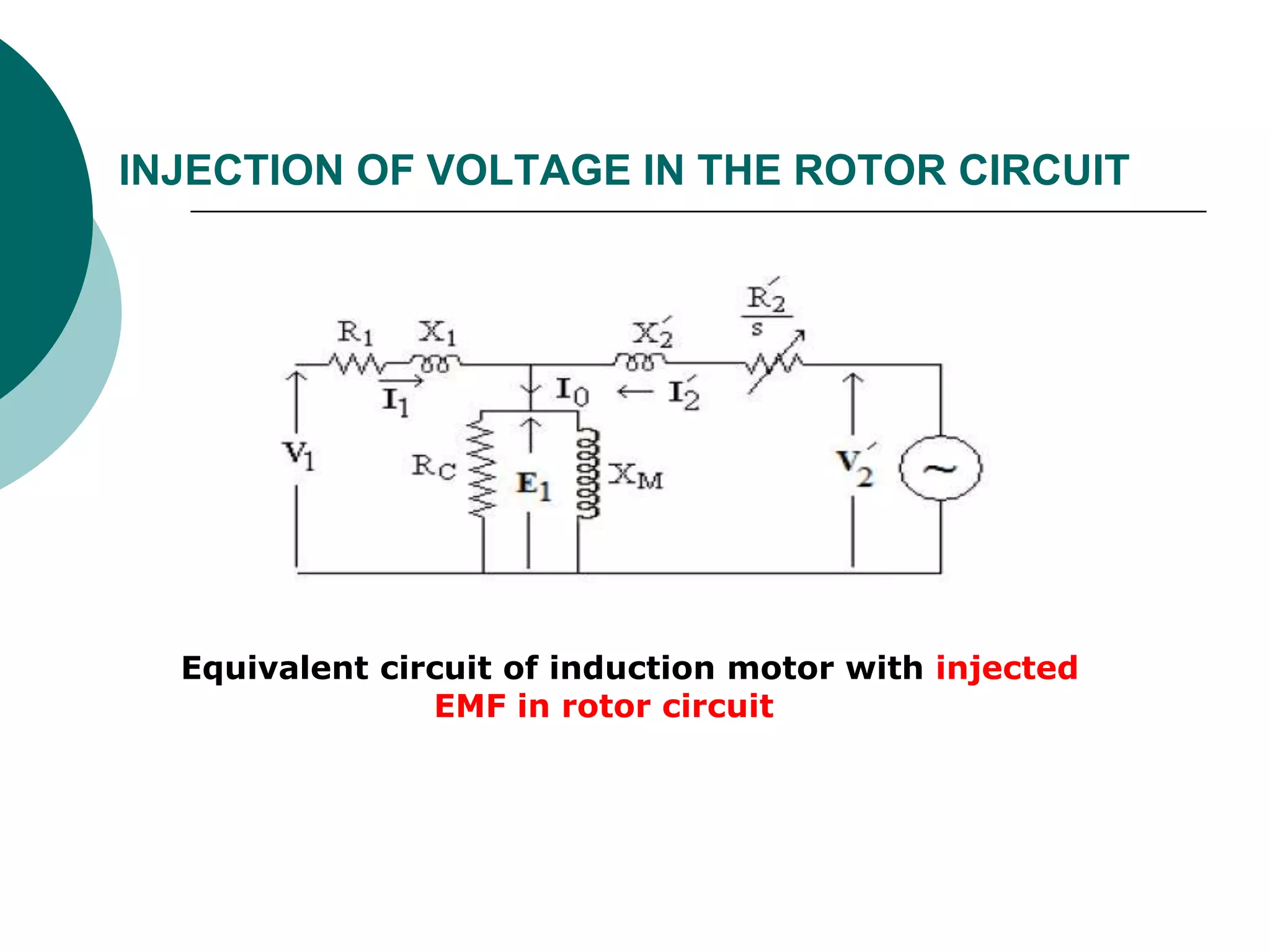
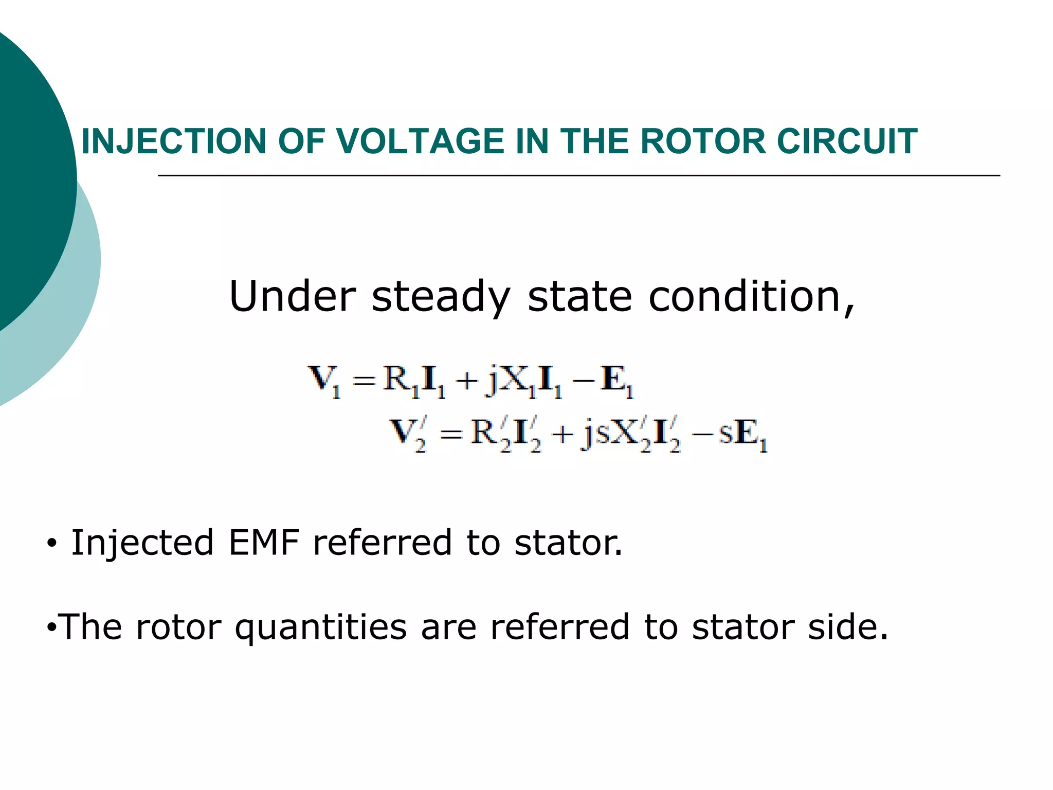
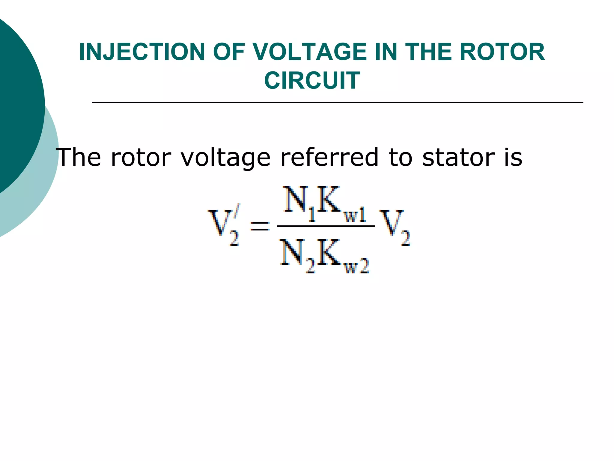
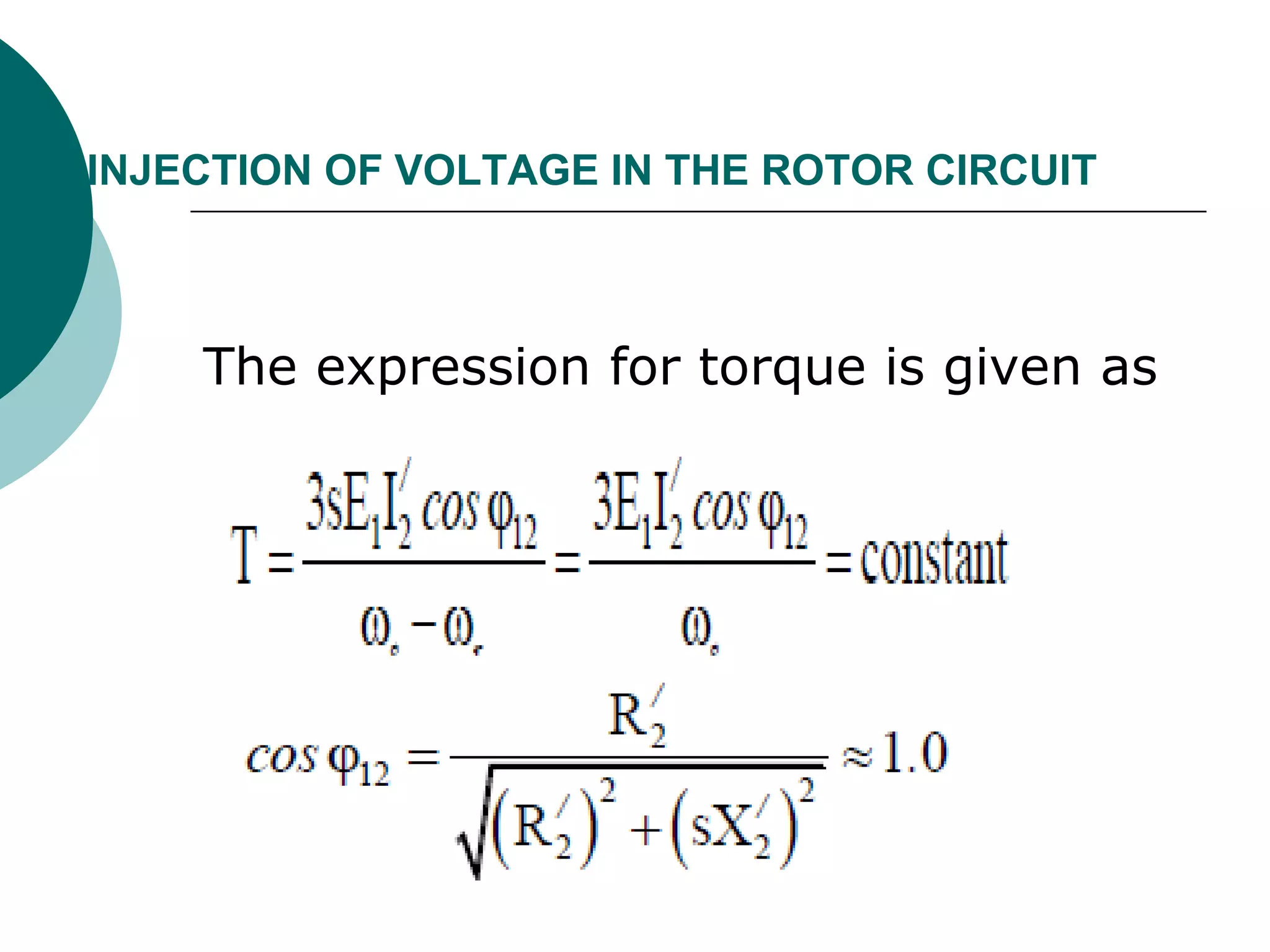
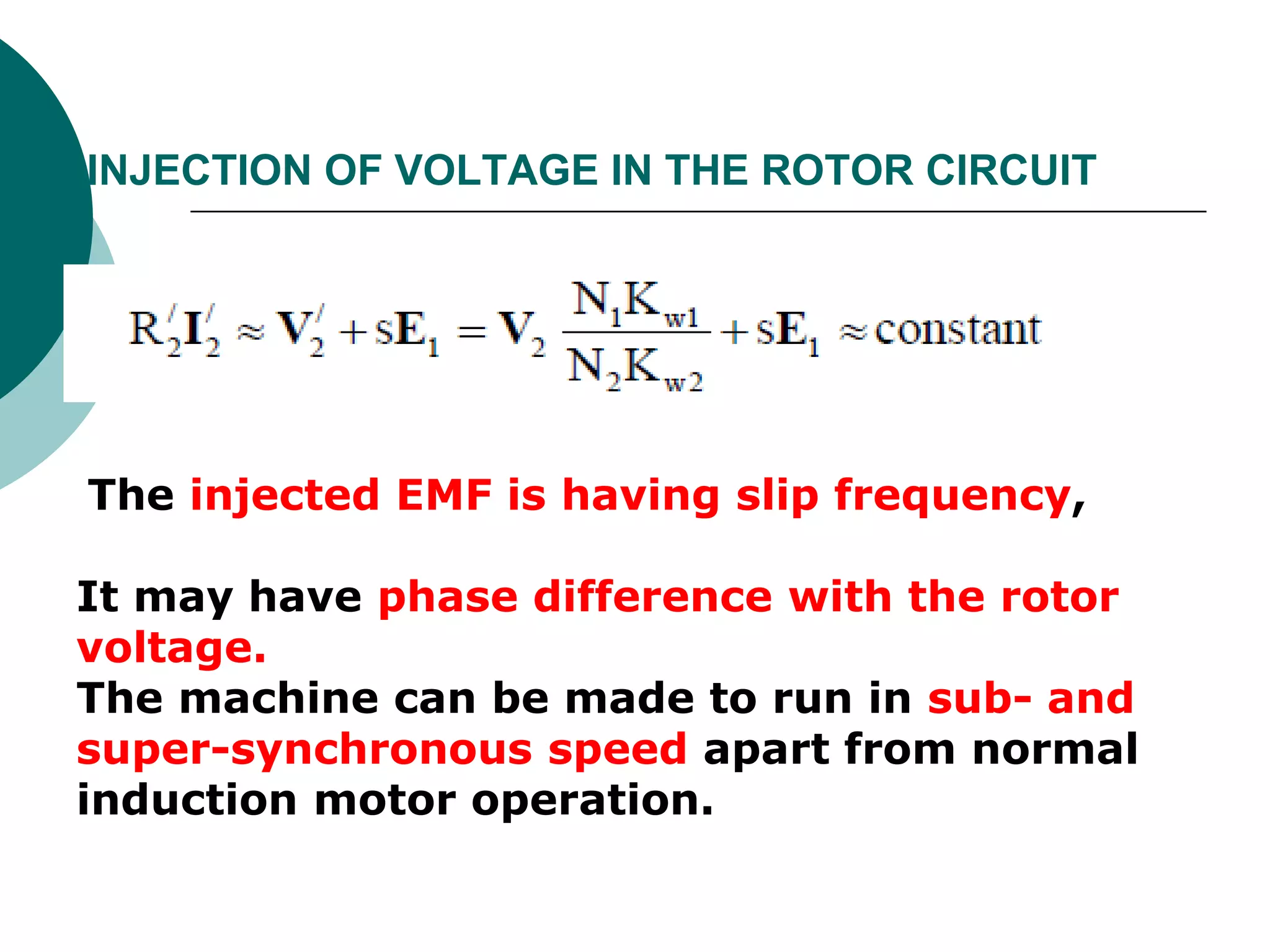
SlideShare a Scribd company logo
UNIT III
ROTOR CONTROLLED INDUCTION MOTOR
DRIVES
SYLLABUS:
STATIC ROTOR RESISTANCE CONTROL
INJECTION OF VOLTAGE IN THE ROTOR CIRCUIT
STATIC SCHERIBIUS DRIVES
POWER FACTOR CONSIDERATIONS
MODIFIED KRAMMER DRIVE
Introduction
The portion of air gap power which is not
converted into mechanical power is called slip
power
Slip rings allow easy recovery of the slip
power
It can be electronically controlled to control
the speed of the motor.
Introduction
The oldest and simplest technique to invoke this
slip-power recovery induction motor speed control
is to mechanically vary the rotor resistance
Rotor resistance cotrol
.
Slip-power recovery drives - applications
 Large-capacity pumps and fan drives
 Variable-speed wind energy systems
 Shipboard VSCF (variable-speed/constant
frequency) systems
 Variable speed hydro-pumps/generators
 Utility system flywheel energy storage
systems
Speed Control by Rotor Rheostat
The torque-slip equation for an induction
motor is given by:
 
2
2 2 2
3 .
2 / ( )
sr
e
e s r e ls lr
VRP
T
s R R s L L 
 
  
    
Speed Control by Rotor Rheostat
(cont’d)
Speed Control by Rotor Rheostat
(cont’d)
1. Very simple,
2. Low cost
3. Good power factor
4. High torque to current ratio
5. Wide range of speed
6. Including starting and braking
7. It is also very inefficient because the slip
energy is wasted in the rotor resistance.
Static Rotor Rheostat control
It is also very inefficient because the slip
energy is wasted in the rotor resistance
Types of slip power recovery
schemes
Instead of wasting the slip power in the
rotor circuit resistance, a better approach
is to convert it to ac line power and return
it back to the line.
Static Kramer Drive - only allows
operation at sub-synchronous speed.
Static Scherbius Drive - allows operation
above and below synchronous speed.
Static Kramer Drive
A schematic of the static Kramer drive is
shown below:
Static Kramer Drive (cont’d)
The machine air gap flux is constant.
The rotor current is ideally a 6-step wave
in phase with the rotor voltage.
Static Kramer Drive-phasor diagram
The motor fundamental phasor diagram
referred to the stator is as shown
Vs = stator phase
voltage,
Is=stator current,
Irf’ = fundamental rotor
current referred to the
stator,
g = air gap flux,
Im=magnetizing current,
=PF angle.
Static Kramer Drive (cont’d)
Voltage Vd is given by:
where s=per unit slip,
VL= stator line voltage
n1=stator-to-rotor turns ratio.
The inverter dc voltage VI is given by:
where n2=transformer turns ratio
=inverter firing angle.
1
1.35 L
d
sV
V
n

2
1.35 cosL
I
V
V
n


Static Kramer Drive (cont’d)
the torque will be expressed as:
1
1.35
2
L
e d
e
VP
T I
n
 
  
 
Static Kramer Drive (cont’d)
The fundamental component of the rotor
current lags the rotor phase voltage by r
because of a commutation overlap angle .
Static Kramer Drive (cont’d)
At zero speed (s=1) the motor acts as a
transformer and all the real power is
transferred back to the line (neglecting
losses).
The motor and inverter only consume
reactive power.
At synchronous speed (s=0) the power factor
is the lowest .
Power factor increases as slip increases.
Static Kramer Drive-starting
methods
The motor is started with switch 1 closed and
switches 2 and 3 open.
As the motor builds up speed, switches 2 and 3
are sequentially closed
Static Kramer Drive-Torque-speed
The torque-speed curves at different firing
angles of the inverter
Harmonics in a Static Kramer Drive
The rectification of slip-power causes
harmonic currents in the rotor which are
reflected back into the stator.
This results in increased machine losses.
Power Factor Improvement
The static Kramer drive is characterized
by poor line PF because of phase
controlled inverter.
One scheme to improve PF is the
commutator-less Kramer drive
Modified Kramer drive(commutator
less kramer drive)
Modified Kramer drive(commutator
less kramer drive)
The slip power taken from the rotor
for speed control by converting it to
mechanical power in an auxiliary
motor mounted on the induction
motor shaft
The mechanical power produced by
the auxiliary motor supplements the
main motor power
Modified Kramer drive(commutator
less kramer drive)
 Better power factor
 Lower harmonic content
 Electric power not feed back to the
line
 Problems associated with the feed
back of power are also eliminated.
Static Scherbius Drive
Static Scherbius Drive (cont’d)
Another approach is to use a double-sided
PWM voltage-fed converter system as
shown below:
Static Scherbius Drive (cont’d)
Line commutated inverter
Static Scherbius Drive (cont’d)
Voltage Vd is given by:
where s=per unit slip,
VL= stator line voltage
n1=stator-to-rotor turns ratio.
The inverter Output ac voltage VI is
given by
where n2=transformer turns ratio
=inverter firing angle.
1
1.35 L
d
sV
V
n

2
1.35 cosL
I
V
V
n


Static Scherbius Drive (cont’d)
1
1.35
2
L
e d
e
VP
T I
n
 
  
 
Torque is approximately proportional to
dc link current since fundamental rotor
current is proportional to dc link current
Power factor considerations
(phasor diagram of static scribius drive at rated
torque)
Power factor considerations
All the phasors are reffered to the stator or line side
 Vs = stator phase voltage,
 Is=stator current,
 Ir’ = fundamental rotor current
referred to the stator,
 g = air gap flux,
 Im=magnetizing current,
 COS  s= Motor PF
 COS  L1 = Fundamental drive PF
Power factor considerations
(conclusions from the phasor diagram)
 The drive power factor is maximized when
“aT’’ is chosen to obtain the drive operation
at the maximum permissible firing angle at
the lowest speed
 The narrower speed range
 The greater the power factor
INJECTION OF VOLTAGE IN THE ROTOR CIRCUIT
 The speed control of three-phase slip-
ring induction motor can be done using
injected EMF in the rotor circuit.
 In the Schrage motor slip frequency
EMF is produced and injected into
secondary winding on the stator by
means of brushes.
INJECTION OF VOLTAGE IN THE ROTOR CIRCUIT
Equivalent circuit of induction motor with injected
EMF in rotor circuit
INJECTION OF VOLTAGE IN THE ROTOR CIRCUIT
Under steady state condition,
• Injected EMF referred to stator.
•The rotor quantities are referred to stator side.
INJECTION OF VOLTAGE IN THE ROTOR
CIRCUIT
The rotor voltage referred to stator is
INJECTION OF VOLTAGE IN THE ROTOR CIRCUIT
The expression for torque is given as
INJECTION OF VOLTAGE IN THE ROTOR CIRCUIT
The injected EMF is having slip frequency,
It may have phase difference with the rotor
voltage.
The machine can be made to run in sub- and
super-synchronous speed apart from normal
induction motor operation.
Unit iii ROTOR CONTROLLED AC DRIVES,ME PED,

More Related Content

What's hot

Power System Analysis Unit - V
Power System Analysis Unit - VPower System Analysis Unit - V
Power System Analysis Unit - V
arunatshare
 
KAUSHAL BOGHNAI
KAUSHAL BOGHNAIKAUSHAL BOGHNAI
KAUSHAL BOGHNAI
kaushal boghani
 
PWM RECTIFIER
PWM RECTIFIERPWM RECTIFIER
PWM RECTIFIER
shiv kapil
 
Lecture 8 steady state stability
Lecture 8 steady state stabilityLecture 8 steady state stability
Lecture 8 steady state stability
Swapnil Gadgune
 
Permanent magnet synchronous motor
Permanent magnet synchronous motorPermanent magnet synchronous motor
Permanent magnet synchronous motor
Zeeshan Akhtar
 
DC DC Converter
DC DC ConverterDC DC Converter
DC DC Converter
Mengstu Fentaw
 
Repulsion motor
Repulsion motorRepulsion motor
Repulsion motor
Muhsin ali
 
Stepper motor
Stepper motorStepper motor
Stepper motor
Anurag Chaudhary
 
speed control of three phase induction motor
speed control of three phase induction motorspeed control of three phase induction motor
speed control of three phase induction motor
Ashvani Shukla
 
PPT ON POWER SYSTEM STABILITY
PPT ON POWER SYSTEM STABILITYPPT ON POWER SYSTEM STABILITY
PPT ON POWER SYSTEM STABILITY
MAHESH CHAND JATAV
 
Electric traction system
Electric traction systemElectric traction system
Electric traction system
AmitKumar6931
 
Synchronous motor
Synchronous motorSynchronous motor
Synchronous motor
Chetan Patil
 
Static kramer system
Static kramer systemStatic kramer system
Static kramer system
Trupesh Rupareliya
 
Control of electric drive
Control of electric driveControl of electric drive
Control of electric drive
Vijay Krishna
 
Speed control of Three phase Induction motor using AC voltage regulator
Speed control of Three phase Induction motor using AC voltage regulatorSpeed control of Three phase Induction motor using AC voltage regulator
Speed control of Three phase Induction motor using AC voltage regulator
Shivagee Raj
 
FACTS DEVICES AND POWER SYSTEM STABILITY ppt
FACTS DEVICES AND POWER SYSTEM STABILITY pptFACTS DEVICES AND POWER SYSTEM STABILITY ppt
FACTS DEVICES AND POWER SYSTEM STABILITY ppt
Mamta Bagoria
 
Industrial Star Delta Starter for a 3-Phase Induction Motor
Industrial Star Delta Starter for a 3-Phase Induction MotorIndustrial Star Delta Starter for a 3-Phase Induction Motor
Industrial Star Delta Starter for a 3-Phase Induction Motor
elprocus
 
Power system stability
Power system stabilityPower system stability
Power system stability
Balaram Das
 
Numerical examples
Numerical examplesNumerical examples
Numerical examples
Felipe Gomes
 
Unit 5 series motor (universal)motors
Unit 5 series motor (universal)motorsUnit 5 series motor (universal)motors
Unit 5 series motor (universal)motors
Er.Meraj Akhtar
 

What's hot (20)

Power System Analysis Unit - V
Power System Analysis Unit - VPower System Analysis Unit - V
Power System Analysis Unit - V
 
KAUSHAL BOGHNAI
KAUSHAL BOGHNAIKAUSHAL BOGHNAI
KAUSHAL BOGHNAI
 
PWM RECTIFIER
PWM RECTIFIERPWM RECTIFIER
PWM RECTIFIER
 
Lecture 8 steady state stability
Lecture 8 steady state stabilityLecture 8 steady state stability
Lecture 8 steady state stability
 
Permanent magnet synchronous motor
Permanent magnet synchronous motorPermanent magnet synchronous motor
Permanent magnet synchronous motor
 
DC DC Converter
DC DC ConverterDC DC Converter
DC DC Converter
 
Repulsion motor
Repulsion motorRepulsion motor
Repulsion motor
 
Stepper motor
Stepper motorStepper motor
Stepper motor
 
speed control of three phase induction motor
speed control of three phase induction motorspeed control of three phase induction motor
speed control of three phase induction motor
 
PPT ON POWER SYSTEM STABILITY
PPT ON POWER SYSTEM STABILITYPPT ON POWER SYSTEM STABILITY
PPT ON POWER SYSTEM STABILITY
 
Electric traction system
Electric traction systemElectric traction system
Electric traction system
 
Synchronous motor
Synchronous motorSynchronous motor
Synchronous motor
 
Static kramer system
Static kramer systemStatic kramer system
Static kramer system
 
Control of electric drive
Control of electric driveControl of electric drive
Control of electric drive
 
Speed control of Three phase Induction motor using AC voltage regulator
Speed control of Three phase Induction motor using AC voltage regulatorSpeed control of Three phase Induction motor using AC voltage regulator
Speed control of Three phase Induction motor using AC voltage regulator
 
FACTS DEVICES AND POWER SYSTEM STABILITY ppt
FACTS DEVICES AND POWER SYSTEM STABILITY pptFACTS DEVICES AND POWER SYSTEM STABILITY ppt
FACTS DEVICES AND POWER SYSTEM STABILITY ppt
 
Industrial Star Delta Starter for a 3-Phase Induction Motor
Industrial Star Delta Starter for a 3-Phase Induction MotorIndustrial Star Delta Starter for a 3-Phase Induction Motor
Industrial Star Delta Starter for a 3-Phase Induction Motor
 
Power system stability
Power system stabilityPower system stability
Power system stability
 
Numerical examples
Numerical examplesNumerical examples
Numerical examples
 
Unit 5 series motor (universal)motors
Unit 5 series motor (universal)motorsUnit 5 series motor (universal)motors
Unit 5 series motor (universal)motors
 

Similar to Unit iii ROTOR CONTROLLED AC DRIVES,ME PED,

nestraining-EE-EE Training Autom .ppt
nestraining-EE-EE Training Autom .pptnestraining-EE-EE Training Autom .ppt
nestraining-EE-EE Training Autom .ppt
pramodkommanaboina
 
Switched Reluctance Motor SRM - Introduction
Switched Reluctance Motor SRM - IntroductionSwitched Reluctance Motor SRM - Introduction
Switched Reluctance Motor SRM - Introduction
RuchiGautam28
 
Speed Control Of DC Motor
Speed Control Of DC MotorSpeed Control Of DC Motor
Speed Control Of DC Motor
PRAVEEN KUMAR
 
UNIT-III-EV.pptx
UNIT-III-EV.pptxUNIT-III-EV.pptx
UNIT-III-EV.pptx
Sengolrajan
 
analysis of induction motor drive using slip power recovery scheme
analysis of induction motor drive using slip power recovery schemeanalysis of induction motor drive using slip power recovery scheme
analysis of induction motor drive using slip power recovery scheme
Prakash_13209
 
Electrical energy issues presented by arshad khan chiniot power limited
Electrical energy issues presented by arshad khan chiniot  power limitedElectrical energy issues presented by arshad khan chiniot  power limited
Electrical energy issues presented by arshad khan chiniot power limited
arshadkhanmarwat
 
Chapter 7 Application of Electronic Converters.pdf
Chapter 7 Application of Electronic Converters.pdfChapter 7 Application of Electronic Converters.pdf
Chapter 7 Application of Electronic Converters.pdf
LiewChiaPing
 
Study of Vector Control Algorithm and Inverter design for BLDC Motor, V/f con...
Study of Vector Control Algorithm and Inverter design for BLDC Motor, V/f con...Study of Vector Control Algorithm and Inverter design for BLDC Motor, V/f con...
Study of Vector Control Algorithm and Inverter design for BLDC Motor, V/f con...Amol Mahurkar
 
three phase induction motor drive
three phase induction motor drivethree phase induction motor drive
three phase induction motor drive
Ratnesh Verma
 
Speed control methods of motor
Speed control methods of motorSpeed control methods of motor
Introduction to vfd
Introduction to vfdIntroduction to vfd
Introduction to vfd
rrsurani
 
ED_Ind_Motor_Rotor.ppt
ED_Ind_Motor_Rotor.pptED_Ind_Motor_Rotor.ppt
ED_Ind_Motor_Rotor.ppt
BishnuPrasadMuni1
 
POWER SYSTEM ANALYSIS-3
POWER SYSTEM ANALYSIS-3POWER SYSTEM ANALYSIS-3
POWER SYSTEM ANALYSIS-3
M Ugur Kebir
 
Drives training
Drives trainingDrives training
Drives training
Arnab Ganguly
 
Speed Control of DC Motor.pdf
Speed Control of DC Motor.pdfSpeed Control of DC Motor.pdf
Speed Control of DC Motor.pdf
MdJobairulAlam1
 
braking.ppt
braking.pptbraking.ppt
braking.ppt
koperundeviG
 
Dc machines1
Dc machines1Dc machines1
Dc machines1
satyajit patra
 

Similar to Unit iii ROTOR CONTROLLED AC DRIVES,ME PED, (20)

nestraining-EE-EE Training Autom .ppt
nestraining-EE-EE Training Autom .pptnestraining-EE-EE Training Autom .ppt
nestraining-EE-EE Training Autom .ppt
 
Switched Reluctance Motor SRM - Introduction
Switched Reluctance Motor SRM - IntroductionSwitched Reluctance Motor SRM - Introduction
Switched Reluctance Motor SRM - Introduction
 
Speed Control Of DC Motor
Speed Control Of DC MotorSpeed Control Of DC Motor
Speed Control Of DC Motor
 
UNIT-III-EV.pptx
UNIT-III-EV.pptxUNIT-III-EV.pptx
UNIT-III-EV.pptx
 
analysis of induction motor drive using slip power recovery scheme
analysis of induction motor drive using slip power recovery schemeanalysis of induction motor drive using slip power recovery scheme
analysis of induction motor drive using slip power recovery scheme
 
Electrical energy issues presented by arshad khan chiniot power limited
Electrical energy issues presented by arshad khan chiniot  power limitedElectrical energy issues presented by arshad khan chiniot  power limited
Electrical energy issues presented by arshad khan chiniot power limited
 
Chapter 7 Application of Electronic Converters.pdf
Chapter 7 Application of Electronic Converters.pdfChapter 7 Application of Electronic Converters.pdf
Chapter 7 Application of Electronic Converters.pdf
 
Study of Vector Control Algorithm and Inverter design for BLDC Motor, V/f con...
Study of Vector Control Algorithm and Inverter design for BLDC Motor, V/f con...Study of Vector Control Algorithm and Inverter design for BLDC Motor, V/f con...
Study of Vector Control Algorithm and Inverter design for BLDC Motor, V/f con...
 
three phase induction motor drive
three phase induction motor drivethree phase induction motor drive
three phase induction motor drive
 
Speed control methods of motor
Speed control methods of motorSpeed control methods of motor
Speed control methods of motor
 
PROJECT SEMINAR
PROJECT SEMINARPROJECT SEMINAR
PROJECT SEMINAR
 
Introduction to vfd
Introduction to vfdIntroduction to vfd
Introduction to vfd
 
Inverter Control.ppsx
Inverter Control.ppsxInverter Control.ppsx
Inverter Control.ppsx
 
Electricmotor2
Electricmotor2Electricmotor2
Electricmotor2
 
ED_Ind_Motor_Rotor.ppt
ED_Ind_Motor_Rotor.pptED_Ind_Motor_Rotor.ppt
ED_Ind_Motor_Rotor.ppt
 
POWER SYSTEM ANALYSIS-3
POWER SYSTEM ANALYSIS-3POWER SYSTEM ANALYSIS-3
POWER SYSTEM ANALYSIS-3
 
Drives training
Drives trainingDrives training
Drives training
 
Speed Control of DC Motor.pdf
Speed Control of DC Motor.pdfSpeed Control of DC Motor.pdf
Speed Control of DC Motor.pdf
 
braking.ppt
braking.pptbraking.ppt
braking.ppt
 
Dc machines1
Dc machines1Dc machines1
Dc machines1
 

More from Dr SOUNDIRARAJ N

UNIT III ANALOG ELECTRONICS (BASIC ELECTRONICS)
UNIT III ANALOG ELECTRONICS (BASIC ELECTRONICS)UNIT III ANALOG ELECTRONICS (BASIC ELECTRONICS)
UNIT III ANALOG ELECTRONICS (BASIC ELECTRONICS)
Dr SOUNDIRARAJ N
 
UNIT I CONTROL SYSTEM (EC3351).pptx
UNIT I  CONTROL SYSTEM (EC3351).pptxUNIT I  CONTROL SYSTEM (EC3351).pptx
UNIT I CONTROL SYSTEM (EC3351).pptx
Dr SOUNDIRARAJ N
 
Unit v measurements and instrumentation
Unit v measurements and instrumentationUnit v measurements and instrumentation
Unit v measurements and instrumentation
Dr SOUNDIRARAJ N
 
Unit iv electronic devices and circuits
Unit iv electronic devices and circuitsUnit iv electronic devices and circuits
Unit iv electronic devices and circuits
Dr SOUNDIRARAJ N
 
Unit ii ac circuits
Unit ii ac circuitsUnit ii ac circuits
Unit ii ac circuits
Dr SOUNDIRARAJ N
 
Unit i electrical circuits
Unit i electrical circuitsUnit i electrical circuits
Unit i electrical circuits
Dr SOUNDIRARAJ N
 
Speed control of dc motor conventional methods and solid state control
Speed control of dc motor conventional methods and solid state controlSpeed control of dc motor conventional methods and solid state control
Speed control of dc motor conventional methods and solid state control
Dr SOUNDIRARAJ N
 
Starting methods of dc motors
Starting methods of dc motorsStarting methods of dc motors
Starting methods of dc motors
Dr SOUNDIRARAJ N
 
Unit v conventional and solid state speed control of ac drives
Unit v conventional and solid state speed control of ac drivesUnit v conventional and solid state speed control of ac drives
Unit v conventional and solid state speed control of ac drives
Dr SOUNDIRARAJ N
 
Unit iv conventional and solid state speed control of dc motors
Unit iv conventional and solid state speed control of dc motorsUnit iv conventional and solid state speed control of dc motors
Unit iv conventional and solid state speed control of dc motors
Dr SOUNDIRARAJ N
 
Dc motor starters
Dc motor startersDc motor starters
Dc motor starters
Dr SOUNDIRARAJ N
 
Unit iv wind energy
Unit iv wind energyUnit iv wind energy
Unit iv wind energy
Dr SOUNDIRARAJ N
 
Unit iii solar energy storage and applications
Unit iii solar energy storage and applicationsUnit iii solar energy storage and applications
Unit iii solar energy storage and applications
Dr SOUNDIRARAJ N
 
SOLID STATE AC DRIVES ,UNIT V,ME (PE&D),ANNAUNIVERSITY SYLLABUS
SOLID STATE AC DRIVES ,UNIT V,ME (PE&D),ANNAUNIVERSITY SYLLABUSSOLID STATE AC DRIVES ,UNIT V,ME (PE&D),ANNAUNIVERSITY SYLLABUS
SOLID STATE AC DRIVES ,UNIT V,ME (PE&D),ANNAUNIVERSITY SYLLABUS
Dr SOUNDIRARAJ N
 
Unit iv field oriented control ,solid state ac drives,ME PE&D
Unit iv field oriented control ,solid state ac drives,ME PE&DUnit iv field oriented control ,solid state ac drives,ME PE&D
Unit iv field oriented control ,solid state ac drives,ME PE&D
Dr SOUNDIRARAJ N
 
Unit v geothermal energy ,renewable energy sources,ORO551
Unit  v geothermal energy ,renewable energy sources,ORO551Unit  v geothermal energy ,renewable energy sources,ORO551
Unit v geothermal energy ,renewable energy sources,ORO551
Dr SOUNDIRARAJ N
 

More from Dr SOUNDIRARAJ N (16)

UNIT III ANALOG ELECTRONICS (BASIC ELECTRONICS)
UNIT III ANALOG ELECTRONICS (BASIC ELECTRONICS)UNIT III ANALOG ELECTRONICS (BASIC ELECTRONICS)
UNIT III ANALOG ELECTRONICS (BASIC ELECTRONICS)
 
UNIT I CONTROL SYSTEM (EC3351).pptx
UNIT I  CONTROL SYSTEM (EC3351).pptxUNIT I  CONTROL SYSTEM (EC3351).pptx
UNIT I CONTROL SYSTEM (EC3351).pptx
 
Unit v measurements and instrumentation
Unit v measurements and instrumentationUnit v measurements and instrumentation
Unit v measurements and instrumentation
 
Unit iv electronic devices and circuits
Unit iv electronic devices and circuitsUnit iv electronic devices and circuits
Unit iv electronic devices and circuits
 
Unit ii ac circuits
Unit ii ac circuitsUnit ii ac circuits
Unit ii ac circuits
 
Unit i electrical circuits
Unit i electrical circuitsUnit i electrical circuits
Unit i electrical circuits
 
Speed control of dc motor conventional methods and solid state control
Speed control of dc motor conventional methods and solid state controlSpeed control of dc motor conventional methods and solid state control
Speed control of dc motor conventional methods and solid state control
 
Starting methods of dc motors
Starting methods of dc motorsStarting methods of dc motors
Starting methods of dc motors
 
Unit v conventional and solid state speed control of ac drives
Unit v conventional and solid state speed control of ac drivesUnit v conventional and solid state speed control of ac drives
Unit v conventional and solid state speed control of ac drives
 
Unit iv conventional and solid state speed control of dc motors
Unit iv conventional and solid state speed control of dc motorsUnit iv conventional and solid state speed control of dc motors
Unit iv conventional and solid state speed control of dc motors
 
Dc motor starters
Dc motor startersDc motor starters
Dc motor starters
 
Unit iv wind energy
Unit iv wind energyUnit iv wind energy
Unit iv wind energy
 
Unit iii solar energy storage and applications
Unit iii solar energy storage and applicationsUnit iii solar energy storage and applications
Unit iii solar energy storage and applications
 
SOLID STATE AC DRIVES ,UNIT V,ME (PE&D),ANNAUNIVERSITY SYLLABUS
SOLID STATE AC DRIVES ,UNIT V,ME (PE&D),ANNAUNIVERSITY SYLLABUSSOLID STATE AC DRIVES ,UNIT V,ME (PE&D),ANNAUNIVERSITY SYLLABUS
SOLID STATE AC DRIVES ,UNIT V,ME (PE&D),ANNAUNIVERSITY SYLLABUS
 
Unit iv field oriented control ,solid state ac drives,ME PE&D
Unit iv field oriented control ,solid state ac drives,ME PE&DUnit iv field oriented control ,solid state ac drives,ME PE&D
Unit iv field oriented control ,solid state ac drives,ME PE&D
 
Unit v geothermal energy ,renewable energy sources,ORO551
Unit  v geothermal energy ,renewable energy sources,ORO551Unit  v geothermal energy ,renewable energy sources,ORO551
Unit v geothermal energy ,renewable energy sources,ORO551
 

Recently uploaded

Student information management system project report ii.pdf
Student information management system project report ii.pdfStudent information management system project report ii.pdf
Student information management system project report ii.pdf
Kamal Acharya
 
一比一原版(SFU毕业证)西蒙菲莎大学毕业证成绩单如何办理
一比一原版(SFU毕业证)西蒙菲莎大学毕业证成绩单如何办理一比一原版(SFU毕业证)西蒙菲莎大学毕业证成绩单如何办理
一比一原版(SFU毕业证)西蒙菲莎大学毕业证成绩单如何办理
bakpo1
 
Standard Reomte Control Interface - Neometrix
Standard Reomte Control Interface - NeometrixStandard Reomte Control Interface - Neometrix
Standard Reomte Control Interface - Neometrix
Neometrix_Engineering_Pvt_Ltd
 
weather web application report.pdf
weather web application report.pdfweather web application report.pdf
weather web application report.pdf
Pratik Pawar
 
Final project report on grocery store management system..pdf
Final project report on grocery store management system..pdfFinal project report on grocery store management system..pdf
Final project report on grocery store management system..pdf
Kamal Acharya
 
J.Yang, ICLR 2024, MLILAB, KAIST AI.pdf
J.Yang,  ICLR 2024, MLILAB, KAIST AI.pdfJ.Yang,  ICLR 2024, MLILAB, KAIST AI.pdf
J.Yang, ICLR 2024, MLILAB, KAIST AI.pdf
MLILAB
 
ethical hacking-mobile hacking methods.ppt
ethical hacking-mobile hacking methods.pptethical hacking-mobile hacking methods.ppt
ethical hacking-mobile hacking methods.ppt
Jayaprasanna4
 
COLLEGE BUS MANAGEMENT SYSTEM PROJECT REPORT.pdf
COLLEGE BUS MANAGEMENT SYSTEM PROJECT REPORT.pdfCOLLEGE BUS MANAGEMENT SYSTEM PROJECT REPORT.pdf
COLLEGE BUS MANAGEMENT SYSTEM PROJECT REPORT.pdf
Kamal Acharya
 
The role of big data in decision making.
The role of big data in decision making.The role of big data in decision making.
The role of big data in decision making.
ankuprajapati0525
 
ethical hacking in wireless-hacking1.ppt
ethical hacking in wireless-hacking1.pptethical hacking in wireless-hacking1.ppt
ethical hacking in wireless-hacking1.ppt
Jayaprasanna4
 
Water Industry Process Automation and Control Monthly - May 2024.pdf
Water Industry Process Automation and Control Monthly - May 2024.pdfWater Industry Process Automation and Control Monthly - May 2024.pdf
Water Industry Process Automation and Control Monthly - May 2024.pdf
Water Industry Process Automation & Control
 
Cosmetic shop management system project report.pdf
Cosmetic shop management system project report.pdfCosmetic shop management system project report.pdf
Cosmetic shop management system project report.pdf
Kamal Acharya
 
Forklift Classes Overview by Intella Parts
Forklift Classes Overview by Intella PartsForklift Classes Overview by Intella Parts
Forklift Classes Overview by Intella Parts
Intella Parts
 
Nuclear Power Economics and Structuring 2024
Nuclear Power Economics and Structuring 2024Nuclear Power Economics and Structuring 2024
Nuclear Power Economics and Structuring 2024
Massimo Talia
 
Event Management System Vb Net Project Report.pdf
Event Management System Vb Net  Project Report.pdfEvent Management System Vb Net  Project Report.pdf
Event Management System Vb Net Project Report.pdf
Kamal Acharya
 
Architectural Portfolio Sean Lockwood
Architectural Portfolio Sean LockwoodArchitectural Portfolio Sean Lockwood
Architectural Portfolio Sean Lockwood
seandesed
 
Hybrid optimization of pumped hydro system and solar- Engr. Abdul-Azeez.pdf
Hybrid optimization of pumped hydro system and solar- Engr. Abdul-Azeez.pdfHybrid optimization of pumped hydro system and solar- Engr. Abdul-Azeez.pdf
Hybrid optimization of pumped hydro system and solar- Engr. Abdul-Azeez.pdf
fxintegritypublishin
 
Halogenation process of chemical process industries
Halogenation process of chemical process industriesHalogenation process of chemical process industries
Halogenation process of chemical process industries
MuhammadTufail242431
 
Democratizing Fuzzing at Scale by Abhishek Arya
Democratizing Fuzzing at Scale by Abhishek AryaDemocratizing Fuzzing at Scale by Abhishek Arya
Democratizing Fuzzing at Scale by Abhishek Arya
abh.arya
 
CME397 Surface Engineering- Professional Elective
CME397 Surface Engineering- Professional ElectiveCME397 Surface Engineering- Professional Elective
CME397 Surface Engineering- Professional Elective
karthi keyan
 

Recently uploaded (20)

Student information management system project report ii.pdf
Student information management system project report ii.pdfStudent information management system project report ii.pdf
Student information management system project report ii.pdf
 
一比一原版(SFU毕业证)西蒙菲莎大学毕业证成绩单如何办理
一比一原版(SFU毕业证)西蒙菲莎大学毕业证成绩单如何办理一比一原版(SFU毕业证)西蒙菲莎大学毕业证成绩单如何办理
一比一原版(SFU毕业证)西蒙菲莎大学毕业证成绩单如何办理
 
Standard Reomte Control Interface - Neometrix
Standard Reomte Control Interface - NeometrixStandard Reomte Control Interface - Neometrix
Standard Reomte Control Interface - Neometrix
 
weather web application report.pdf
weather web application report.pdfweather web application report.pdf
weather web application report.pdf
 
Final project report on grocery store management system..pdf
Final project report on grocery store management system..pdfFinal project report on grocery store management system..pdf
Final project report on grocery store management system..pdf
 
J.Yang, ICLR 2024, MLILAB, KAIST AI.pdf
J.Yang,  ICLR 2024, MLILAB, KAIST AI.pdfJ.Yang,  ICLR 2024, MLILAB, KAIST AI.pdf
J.Yang, ICLR 2024, MLILAB, KAIST AI.pdf
 
ethical hacking-mobile hacking methods.ppt
ethical hacking-mobile hacking methods.pptethical hacking-mobile hacking methods.ppt
ethical hacking-mobile hacking methods.ppt
 
COLLEGE BUS MANAGEMENT SYSTEM PROJECT REPORT.pdf
COLLEGE BUS MANAGEMENT SYSTEM PROJECT REPORT.pdfCOLLEGE BUS MANAGEMENT SYSTEM PROJECT REPORT.pdf
COLLEGE BUS MANAGEMENT SYSTEM PROJECT REPORT.pdf
 
The role of big data in decision making.
The role of big data in decision making.The role of big data in decision making.
The role of big data in decision making.
 
ethical hacking in wireless-hacking1.ppt
ethical hacking in wireless-hacking1.pptethical hacking in wireless-hacking1.ppt
ethical hacking in wireless-hacking1.ppt
 
Water Industry Process Automation and Control Monthly - May 2024.pdf
Water Industry Process Automation and Control Monthly - May 2024.pdfWater Industry Process Automation and Control Monthly - May 2024.pdf
Water Industry Process Automation and Control Monthly - May 2024.pdf
 
Cosmetic shop management system project report.pdf
Cosmetic shop management system project report.pdfCosmetic shop management system project report.pdf
Cosmetic shop management system project report.pdf
 
Forklift Classes Overview by Intella Parts
Forklift Classes Overview by Intella PartsForklift Classes Overview by Intella Parts
Forklift Classes Overview by Intella Parts
 
Nuclear Power Economics and Structuring 2024
Nuclear Power Economics and Structuring 2024Nuclear Power Economics and Structuring 2024
Nuclear Power Economics and Structuring 2024
 
Event Management System Vb Net Project Report.pdf
Event Management System Vb Net  Project Report.pdfEvent Management System Vb Net  Project Report.pdf
Event Management System Vb Net Project Report.pdf
 
Architectural Portfolio Sean Lockwood
Architectural Portfolio Sean LockwoodArchitectural Portfolio Sean Lockwood
Architectural Portfolio Sean Lockwood
 
Hybrid optimization of pumped hydro system and solar- Engr. Abdul-Azeez.pdf
Hybrid optimization of pumped hydro system and solar- Engr. Abdul-Azeez.pdfHybrid optimization of pumped hydro system and solar- Engr. Abdul-Azeez.pdf
Hybrid optimization of pumped hydro system and solar- Engr. Abdul-Azeez.pdf
 
Halogenation process of chemical process industries
Halogenation process of chemical process industriesHalogenation process of chemical process industries
Halogenation process of chemical process industries
 
Democratizing Fuzzing at Scale by Abhishek Arya
Democratizing Fuzzing at Scale by Abhishek AryaDemocratizing Fuzzing at Scale by Abhishek Arya
Democratizing Fuzzing at Scale by Abhishek Arya
 
CME397 Surface Engineering- Professional Elective
CME397 Surface Engineering- Professional ElectiveCME397 Surface Engineering- Professional Elective
CME397 Surface Engineering- Professional Elective
 

Unit iii ROTOR CONTROLLED AC DRIVES,ME PED,

  • 1. UNIT III ROTOR CONTROLLED INDUCTION MOTOR DRIVES SYLLABUS: STATIC ROTOR RESISTANCE CONTROL INJECTION OF VOLTAGE IN THE ROTOR CIRCUIT STATIC SCHERIBIUS DRIVES POWER FACTOR CONSIDERATIONS MODIFIED KRAMMER DRIVE
  • 2. Introduction The portion of air gap power which is not converted into mechanical power is called slip power Slip rings allow easy recovery of the slip power It can be electronically controlled to control the speed of the motor.
  • 3. Introduction The oldest and simplest technique to invoke this slip-power recovery induction motor speed control is to mechanically vary the rotor resistance Rotor resistance cotrol .
  • 4. Slip-power recovery drives - applications  Large-capacity pumps and fan drives  Variable-speed wind energy systems  Shipboard VSCF (variable-speed/constant frequency) systems  Variable speed hydro-pumps/generators  Utility system flywheel energy storage systems
  • 5. Speed Control by Rotor Rheostat The torque-slip equation for an induction motor is given by:   2 2 2 2 3 . 2 / ( ) sr e e s r e ls lr VRP T s R R s L L           
  • 6. Speed Control by Rotor Rheostat (cont’d)
  • 7. Speed Control by Rotor Rheostat (cont’d) 1. Very simple, 2. Low cost 3. Good power factor 4. High torque to current ratio 5. Wide range of speed 6. Including starting and braking 7. It is also very inefficient because the slip energy is wasted in the rotor resistance.
  • 8. Static Rotor Rheostat control It is also very inefficient because the slip energy is wasted in the rotor resistance
  • 9. Types of slip power recovery schemes Instead of wasting the slip power in the rotor circuit resistance, a better approach is to convert it to ac line power and return it back to the line. Static Kramer Drive - only allows operation at sub-synchronous speed. Static Scherbius Drive - allows operation above and below synchronous speed.
  • 10. Static Kramer Drive A schematic of the static Kramer drive is shown below:
  • 11. Static Kramer Drive (cont’d) The machine air gap flux is constant. The rotor current is ideally a 6-step wave in phase with the rotor voltage.
  • 12. Static Kramer Drive-phasor diagram The motor fundamental phasor diagram referred to the stator is as shown Vs = stator phase voltage, Is=stator current, Irf’ = fundamental rotor current referred to the stator, g = air gap flux, Im=magnetizing current, =PF angle.
  • 13. Static Kramer Drive (cont’d) Voltage Vd is given by: where s=per unit slip, VL= stator line voltage n1=stator-to-rotor turns ratio. The inverter dc voltage VI is given by: where n2=transformer turns ratio =inverter firing angle. 1 1.35 L d sV V n  2 1.35 cosL I V V n  
  • 14. Static Kramer Drive (cont’d) the torque will be expressed as: 1 1.35 2 L e d e VP T I n       
  • 15. Static Kramer Drive (cont’d) The fundamental component of the rotor current lags the rotor phase voltage by r because of a commutation overlap angle .
  • 16. Static Kramer Drive (cont’d) At zero speed (s=1) the motor acts as a transformer and all the real power is transferred back to the line (neglecting losses). The motor and inverter only consume reactive power. At synchronous speed (s=0) the power factor is the lowest . Power factor increases as slip increases.
  • 17. Static Kramer Drive-starting methods The motor is started with switch 1 closed and switches 2 and 3 open. As the motor builds up speed, switches 2 and 3 are sequentially closed
  • 18. Static Kramer Drive-Torque-speed The torque-speed curves at different firing angles of the inverter
  • 19. Harmonics in a Static Kramer Drive The rectification of slip-power causes harmonic currents in the rotor which are reflected back into the stator. This results in increased machine losses.
  • 20. Power Factor Improvement The static Kramer drive is characterized by poor line PF because of phase controlled inverter. One scheme to improve PF is the commutator-less Kramer drive
  • 22. Modified Kramer drive(commutator less kramer drive) The slip power taken from the rotor for speed control by converting it to mechanical power in an auxiliary motor mounted on the induction motor shaft The mechanical power produced by the auxiliary motor supplements the main motor power
  • 23. Modified Kramer drive(commutator less kramer drive)  Better power factor  Lower harmonic content  Electric power not feed back to the line  Problems associated with the feed back of power are also eliminated.
  • 25. Static Scherbius Drive (cont’d) Another approach is to use a double-sided PWM voltage-fed converter system as shown below:
  • 26. Static Scherbius Drive (cont’d) Line commutated inverter
  • 27. Static Scherbius Drive (cont’d) Voltage Vd is given by: where s=per unit slip, VL= stator line voltage n1=stator-to-rotor turns ratio. The inverter Output ac voltage VI is given by where n2=transformer turns ratio =inverter firing angle. 1 1.35 L d sV V n  2 1.35 cosL I V V n  
  • 29. Static Scherbius Drive (cont’d) 1 1.35 2 L e d e VP T I n        Torque is approximately proportional to dc link current since fundamental rotor current is proportional to dc link current
  • 30. Power factor considerations (phasor diagram of static scribius drive at rated torque)
  • 31. Power factor considerations All the phasors are reffered to the stator or line side  Vs = stator phase voltage,  Is=stator current,  Ir’ = fundamental rotor current referred to the stator,  g = air gap flux,  Im=magnetizing current,  COS  s= Motor PF  COS  L1 = Fundamental drive PF
  • 32. Power factor considerations (conclusions from the phasor diagram)  The drive power factor is maximized when “aT’’ is chosen to obtain the drive operation at the maximum permissible firing angle at the lowest speed  The narrower speed range  The greater the power factor
  • 33. INJECTION OF VOLTAGE IN THE ROTOR CIRCUIT  The speed control of three-phase slip- ring induction motor can be done using injected EMF in the rotor circuit.  In the Schrage motor slip frequency EMF is produced and injected into secondary winding on the stator by means of brushes.
  • 34. INJECTION OF VOLTAGE IN THE ROTOR CIRCUIT Equivalent circuit of induction motor with injected EMF in rotor circuit
  • 35. INJECTION OF VOLTAGE IN THE ROTOR CIRCUIT Under steady state condition, • Injected EMF referred to stator. •The rotor quantities are referred to stator side.
  • 36. INJECTION OF VOLTAGE IN THE ROTOR CIRCUIT The rotor voltage referred to stator is
  • 37. INJECTION OF VOLTAGE IN THE ROTOR CIRCUIT The expression for torque is given as
  • 38. INJECTION OF VOLTAGE IN THE ROTOR CIRCUIT The injected EMF is having slip frequency, It may have phase difference with the rotor voltage. The machine can be made to run in sub- and super-synchronous speed apart from normal induction motor operation.