The document discusses the closed-loop control of DC drives, detailing the control structures involving inner current and outer speed loops that enhance the performance of DC motors. It covers the dynamic modeling of DC motors, including electrical and mechanical equations, and emphasizes the importance of feedback components for stability and accuracy. The benefits and applications of closed-loop control in various industries, such as automation, aerospace, and automotive, are outlined in the context of improving efficiency and reliability.
Electrical Drives
Unit-4
Closed LoopControl of DC Drives
Syllabus:
● Control structure of DC drive
● Inner current loop and outer speed loop
● Dynamic model of dc motor – dynamic equations and transfer
functions
● Modeling of chopper as gain with switching delay, Plant
transfer function for controller design
● Current controller specification and design, Speed controller
specification and design
Prepared by:
Rohan Sharma
Assistant Professor EE
Arya Institute of Engineering Technology &
Management, Jaipur
Rohan Sharma
2.
Introduction to DCDrives
● DC drives are used for controlling the
speed and torque of DC motors in
industrial applications.
● Closed-loop control is a popular
technique used to improve the
performance of DC drives.
Rohan Sharma
3.
Control Structure ofDC Drive
● A closed-loop control system for a DC
drive typically involves using feedback
from a sensor to adjust the voltage or
current supplied to the DC motor.
● The basic components of such a system
are:
● Sensor
● Controller
● Power amplifier
● DC motor
Rohan Sharma
4.
Control Structure ofDC Drive
● Sensor: A sensor is used to measure the speed or position of
the motor shaft, which is used as feedback for the control
system.
● Controller: The controller compares the actual speed or
position of the motor with the desired speed or position, and
generates a control signal to adjust the voltage or current
supplied to the motor.
Rohan Sharma
5.
Control Structure ofDC Drive
● Power amplifier: The power amplifier takes the control signal
from the controller and amplifies it to a level that can drive the
motor.
● DC motor: The DC motor converts the electrical energy supplied
to it into mechanical energy to perform the desired task.
Rohan Sharma
6.
Control Structure ofDC Drive
● The closed-loop control system for a DC drive works by continuously
monitoring the motor speed or position using the sensor, comparing it with the
desired speed or position, and adjusting the voltage or current supplied to the
motor using the controller and power amplifier.
● This feedback loop ensures that any disturbances or changes in the load on the
motor are compensated for, and the motor operates at the desired speed or
position.
● The closed-loop control system for a DC drive can be implemented using
various control techniques such as proportional-integral-derivative (PID)
control, adaptive control, or model-based control. The choice of control
technique depends on the specific application requirements, and the system's
desired performance characteristics such as accuracy, stability, and response
time.
Rohan Sharma
7.
Inner Current Loopand Outer Speed
Loop
● In closed-loop control of DC drives, there
are typically two feedback loops that
work together to control the motor's
speed and torque:
● the inner current loop
● the outer speed loop
Rohan Sharma
8.
Inner Current Loop
●The inner current loop controls the current
supplied to the motor by adjusting the
voltage applied to it. This loop is
responsible for ensuring that the motor
current remains constant despite changes
in the load or supply voltage. It operates at
a faster rate than the outer speed loop and
is responsible for providing fast and
accurate current control.
Rohan Sharma
9.
Inner Current Loop
●The components of the inner current loop
include a current sensor, a current
controller, and a power amplifier. The
current sensor measures the actual
current supplied to the motor, which is
compared to the desired current by the
current controller. The current controller
then generates a control signal that
adjusts the voltage applied to the motor
through the power amplifier.
Rohan Sharma
10.
Outer speed loop:
●The outer speed loop controls the speed
of the motor by adjusting the current
supplied to it. It is responsible for ensuring
that the motor operates at the desired
speed despite changes in the load or other
external factors. This loop operates at a
slower rate than the inner current loop and
is responsible for providing stable and
accurate speed control.
Rohan Sharma
11.
Outer speed loop:
●The components of the outer speed loop
include a speed sensor, a speed controller,
and a current reference generator. The
speed sensor measures the actual speed
of the motor, which is compared to the
desired speed by the speed controller. The
speed controller then generates a control
signal that adjusts the current supplied to
the motor through the current reference
generator.
Rohan Sharma
12.
Inner Current Loopand Outer Speed Loop
● The inner current loop and outer speed
loop work together to provide precise and
stable control of the DC motor.
● The current loop provides fast and
accurate current control, while the speed
loop provides stable and accurate speed
control.
● The interaction between the two loops is
essential to achieve the desired
performance of the motor.
Rohan Sharma
13.
Current Limit Control
●This scheme is used to limit the converter and motor current
below a safe limit during the transient operation. The system
has a current feedback loop with a threshold logic circuit.
Rohan Sharma
14.
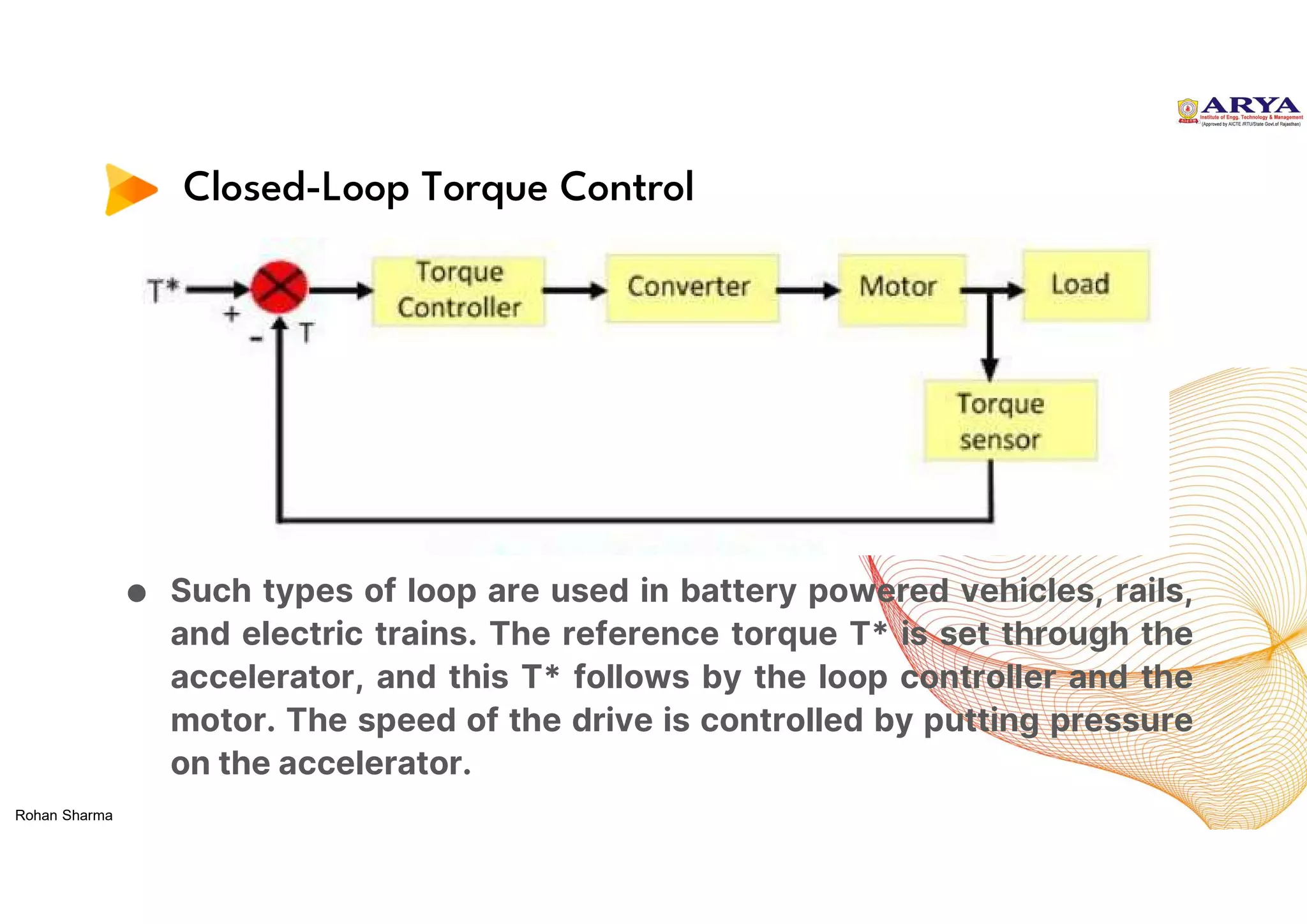
Closed-Loop Torque Control
●Such types of loop are used in battery powered vehicles, rails,
and electric trains. The reference torque T* is set through the
accelerator, and this T* follows by the loop controller and the
motor. The speed of the drive is controlled by putting pressure
on the accelerator.
Rohan Sharma
15.
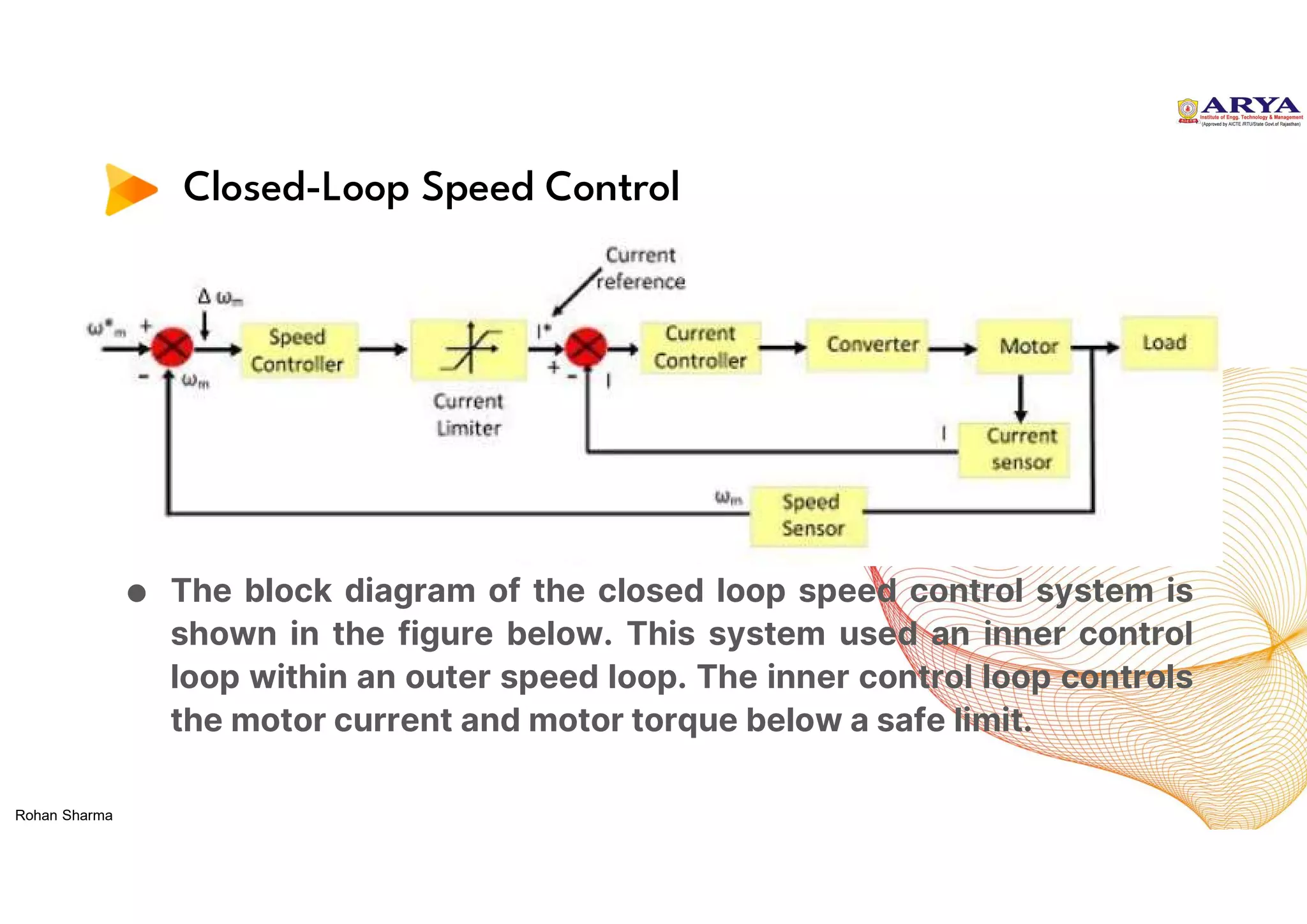
Closed-Loop Speed Control
●The block diagram of the closed loop speed control system is
shown in the figure below. This system used an inner control
loop within an outer speed loop. The inner control loop controls
the motor current and motor torque below a safe limit.
Rohan Sharma
Closed Loop SpeedControl of DC Motor
The converters (rectifiers and
choppers) are built using
semiconductor devices, which have
very low thermal capacity.
Consequently their transient and
steady state current ratings are
same. The dc motors can carry 2 to
3.5 times the rated current during
transient operations of short
duration’s, such as starting, braking
and reversing. Higher the current,
higher is the torque and faster is
the transient response.
Rohan Sharma
18.
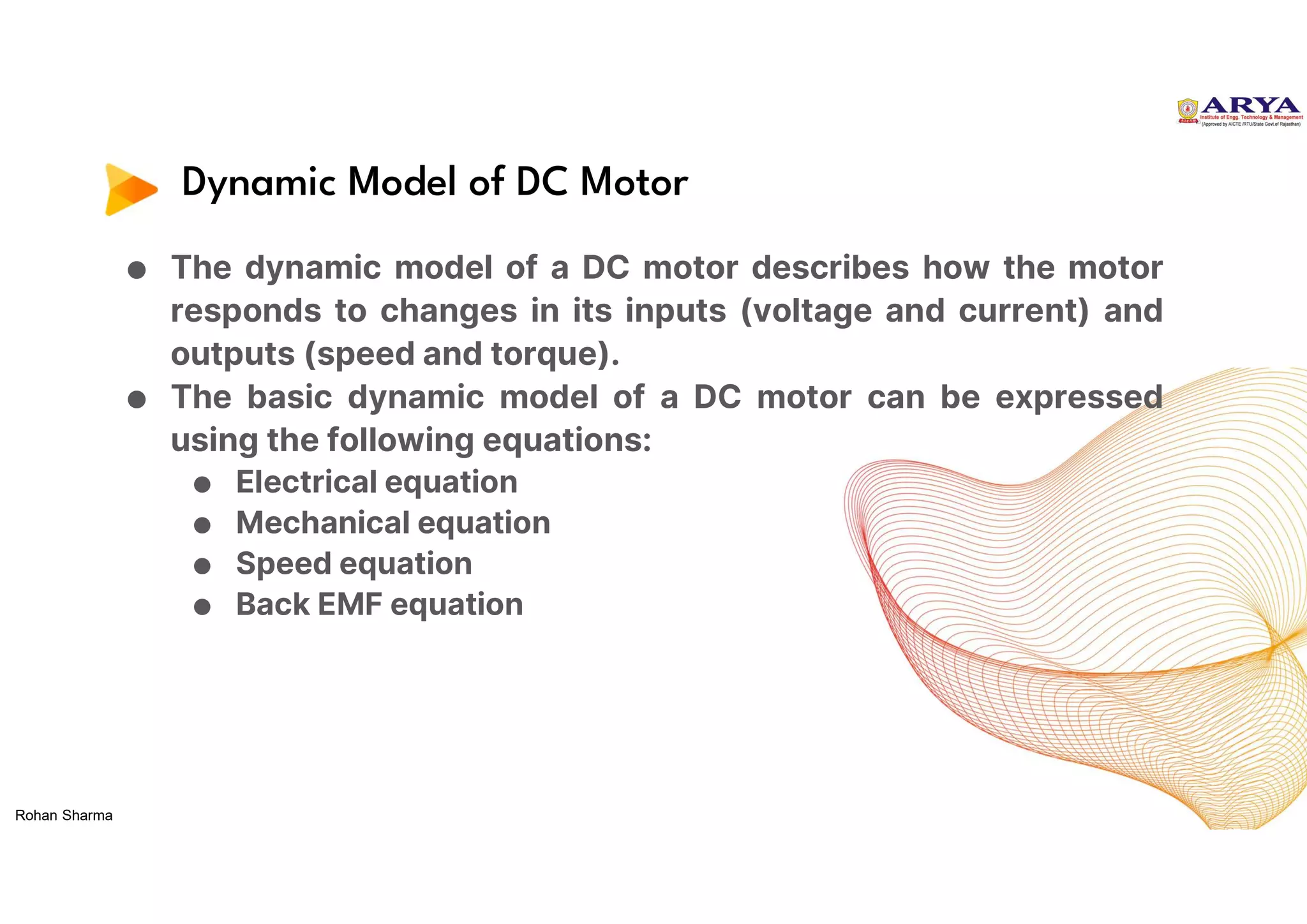
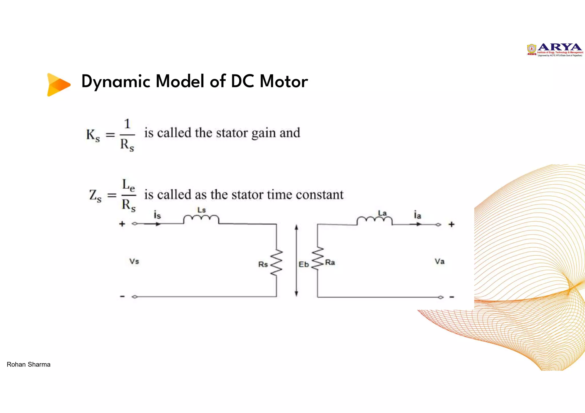
Dynamic Model ofDC Motor
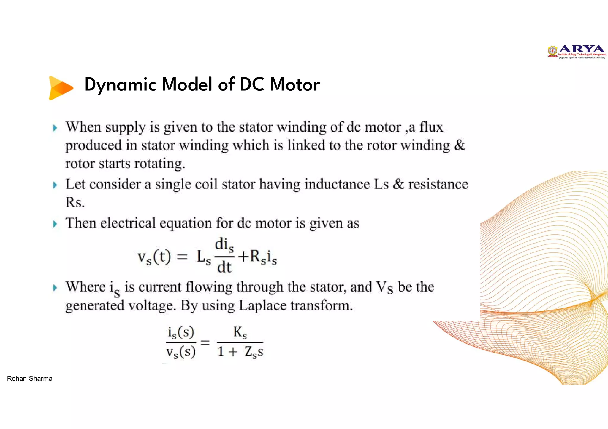
● The dynamic model of a DC motor describes how the motor
responds to changes in its inputs (voltage and current) and
outputs (speed and torque).
● The basic dynamic model of a DC motor can be expressed
using the following equations:
● Electrical equation
● Mechanical equation
● Speed equation
● Back EMF equation
Rohan Sharma
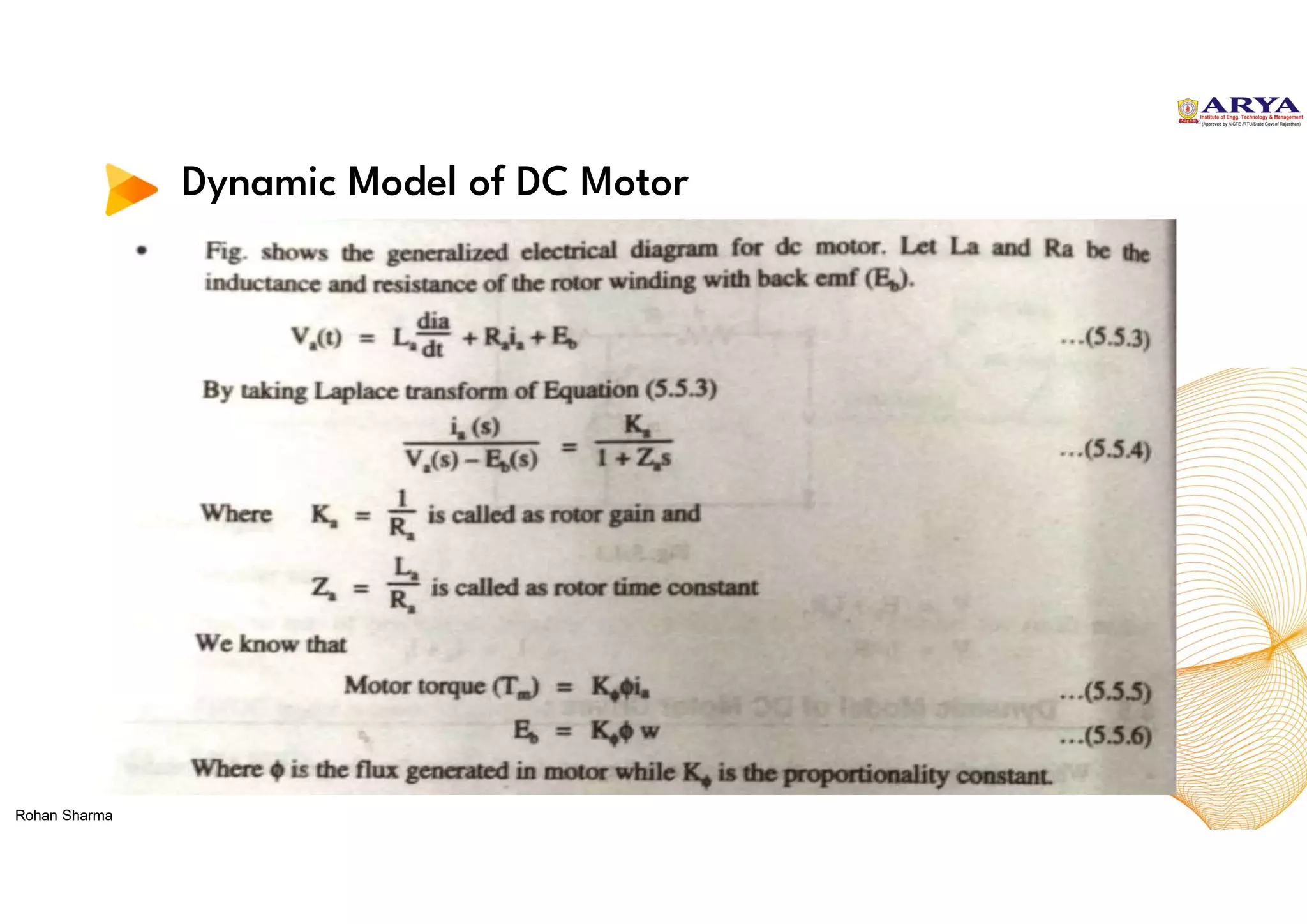
19.
Dynamic Model ofDC Motor
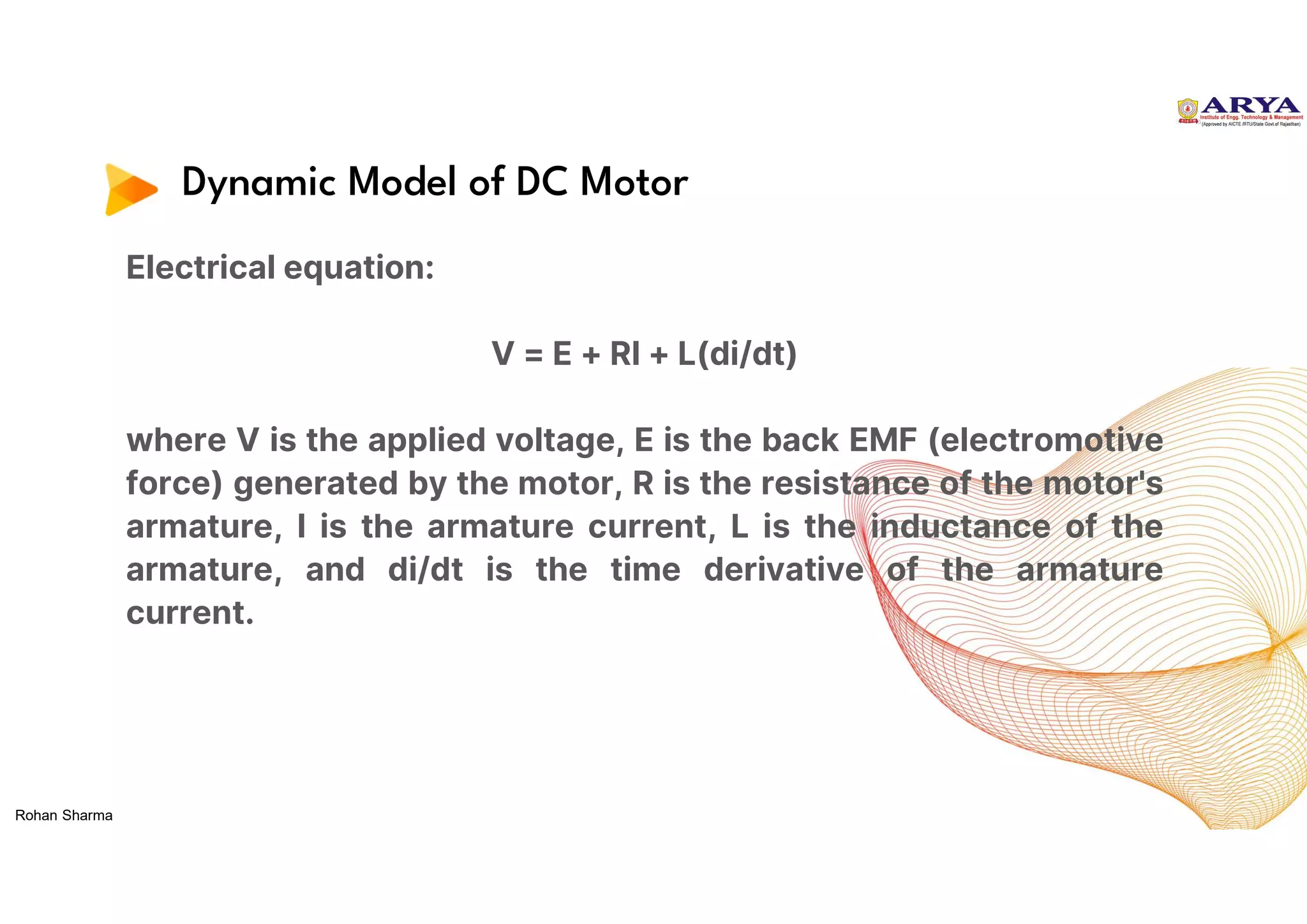
Electrical equation:
V = E + RI + L(di/dt)
where V is the applied voltage, E is the back EMF (electromotive
force) generated by the motor, R is the resistance of the motor's
armature, I is the armature current, L is the inductance of the
armature, and di/dt is the time derivative of the armature
current.
Rohan Sharma
20.
Dynamic Model ofDC Motor
Mechanical equation:
T = kΦI
where T is the torque generated by the motor, k is a constant
that relates the motor's magnetic field strength to its torque, Φ is
the magnetic flux produced by the motor, and I is the armature
current.
Rohan Sharma
21.
Dynamic Model ofDC Motor
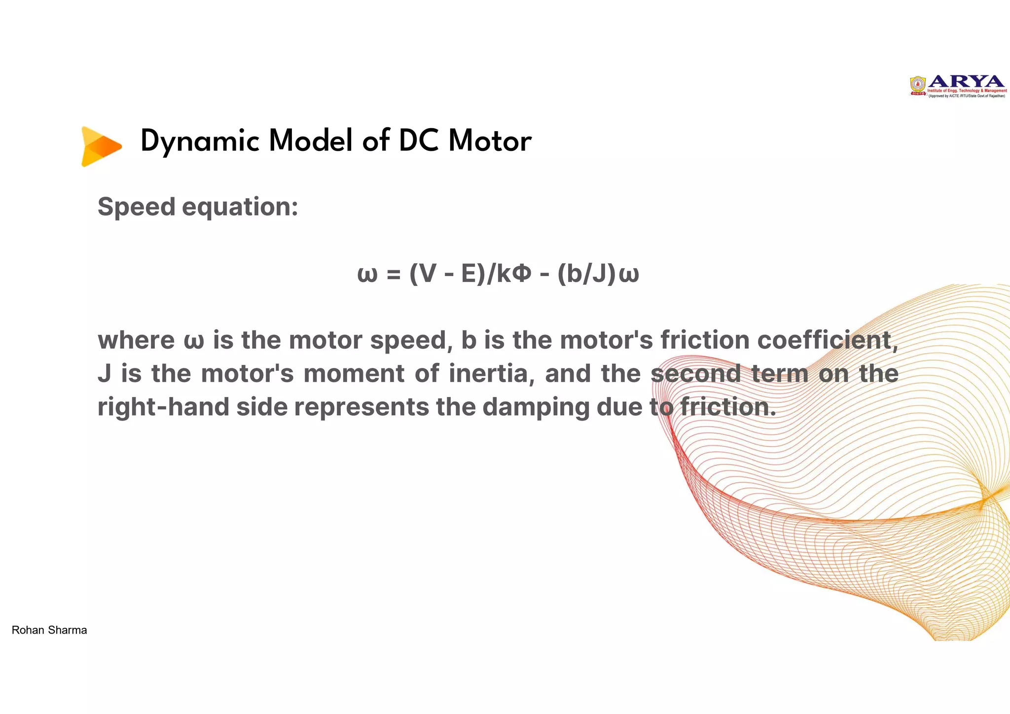
Speed equation:
ω = (V - E)/kΦ - (b/J)ω
where ω is the motor speed, b is the motor's friction coefficient,
J is the motor's moment of inertia, and the second term on the
right-hand side represents the damping due to friction.
Rohan Sharma
22.
Dynamic Model ofDC Motor
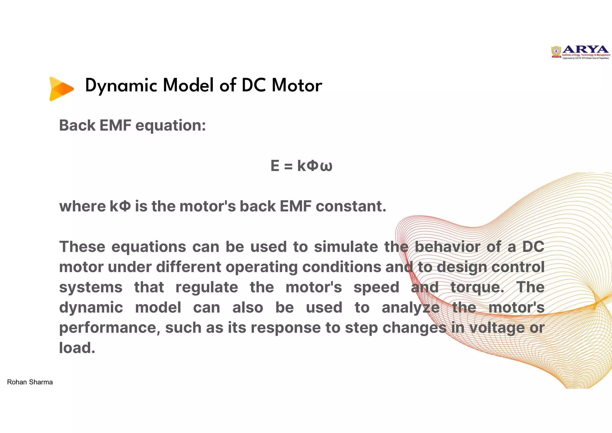
Back EMF equation:
E = kΦω
where kΦ is the motor's back EMF constant.
These equations can be used to simulate the behavior of a DC
motor under different operating conditions and to design control
systems that regulate the motor's speed and torque. The
dynamic model can also be used to analyze the motor's
performance, such as its response to step changes in voltage or
load.
Rohan Sharma
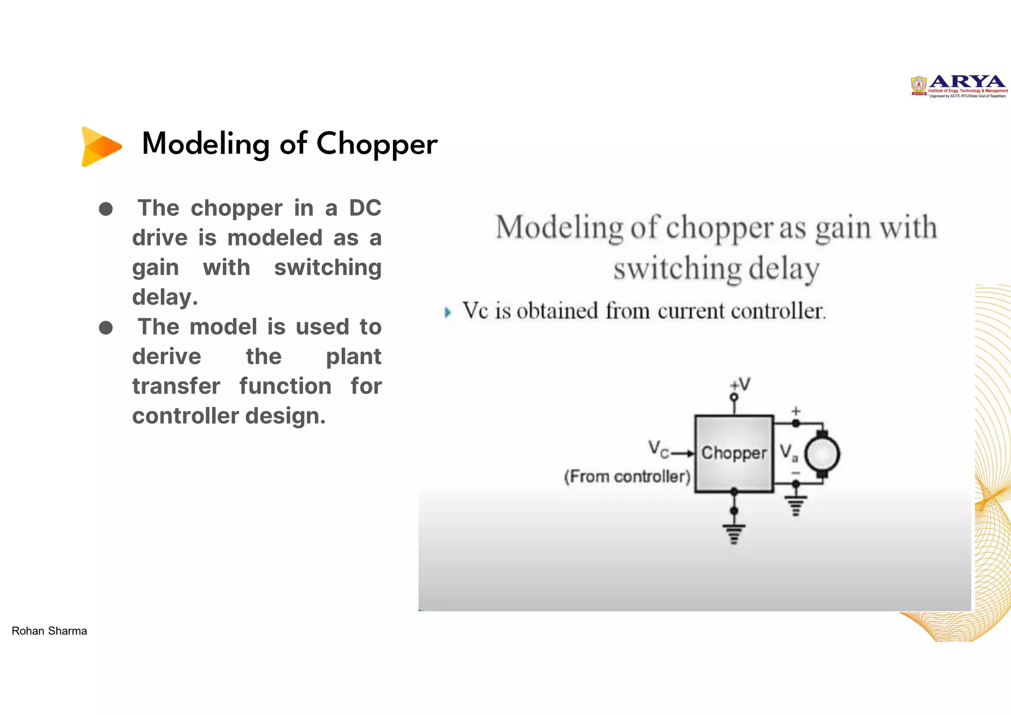
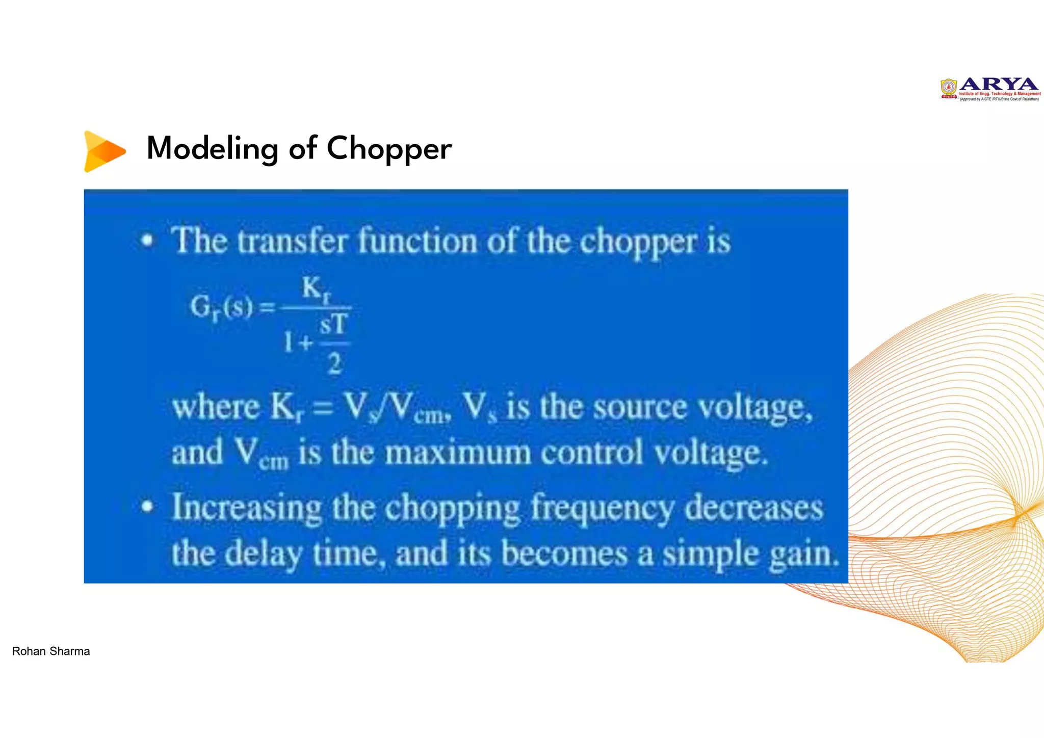
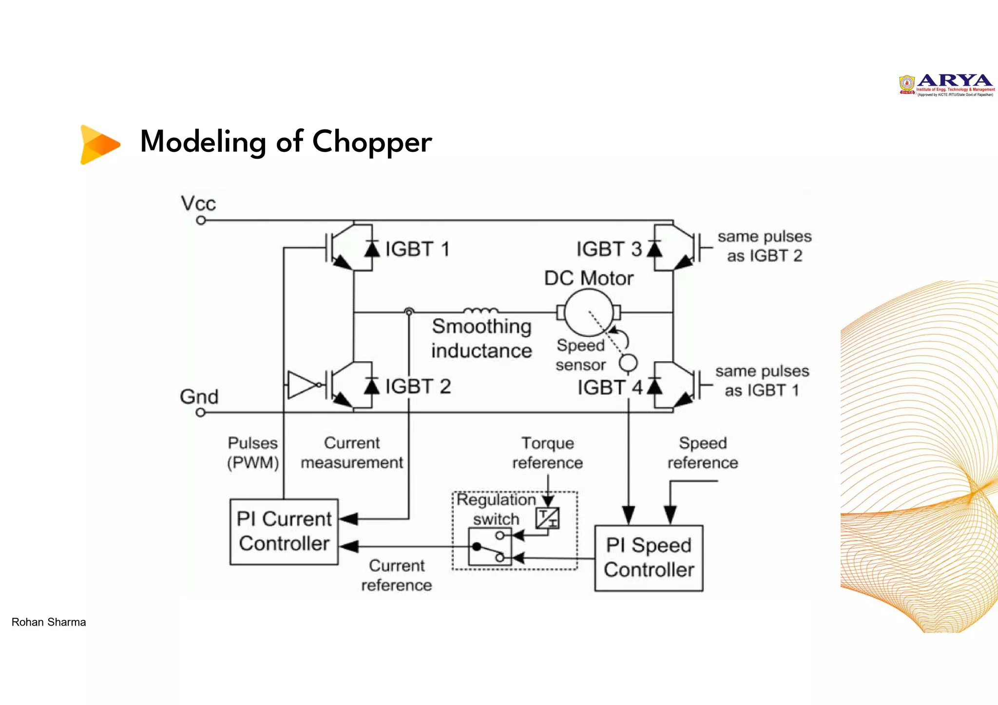
Modeling of Chopper
●The chopper in a DC
drive is modeled as a
gain with switching
delay.
● The model is used to
derive the plant
transfer function for
controller design.
Rohan Sharma
Current Controller Specificationand Design
● In closed-loop control of a DC drive, the current controller is
an important component of the control system. The
specification and design of the current controller depend on
the motor's characteristics and the desired performance
requirements.
● Here are some general steps involved in the specification and
design of a current controller for a closed-loop DC drive:
● Determine the motor parameters: The first step is to measure or
calculate the motor's parameters, such as its resistance,
inductance, and back-EMF constant.
Rohan Sharma
35.
Current Controller Specificationand Design
● Choose the control strategy: Different control strategies
may be used, such as PI control, where the controller
adjusts the current based on the difference between the
desired current and the actual current.
● Determine the controller parameters: The controller
parameters, such as the proportional and integral gains,
are determined based on the desired response time and
stability requirements of the system. These parameters
can be determined using simulation tools or trial-and-
error tuning methods.
Rohan Sharma
36.
Current Controller Specificationand Design
● Implement the controller: The controller can be
implemented using analog or digital circuits, depending
on the specific application.
● Test and tune the controller: The controller's
performance can be tested using simulations or
experiments, and the controller parameters can be
adjusted to optimize the performance of the system.
Rohan Sharma
37.
Advantages of Closed-LoopControl
● Increased accuracy: Closed-loop control allows for more
accurate control of the motor's speed and torque, which can
improve the performance of the drive and reduce wear and tear
on the motor.
● Improved response: Closed-loop control allows for faster
response to changes in the load or operating conditions, which
can improve the drive's performance and efficiency.
● Disturbance rejection: Closed-loop control allows for better
rejection of disturbances, such as changes in the load or supply
voltage, which can improve the drive's stability and reliability.
Rohan Sharma
38.
Advantages of Closed-LoopControl
● Flexibility: Closed-loop control allows for more flexible
operation of the drive, as it can adapt to changes in the load or
operating conditions without requiring manual adjustments.
● Protection: Closed-loop control can provide protection to the
motor by limiting the current or voltage to prevent damage due
to overloading or other operating conditions.
Rohan Sharma
39.
Applications of Closed-LoopControl
● Industrial automation: Closed-loop control is widely used in
industrial automation applications, such as manufacturing
processes, assembly lines, and robotics.
● Aerospace and defense: Closed-loop control is used in aircraft
control systems, missile guidance systems, and unmanned
aerial vehicles (UAVs).
● Automotive: Closed-loop control is used in automotive
systems, such as engine control, anti-lock braking systems
(ABS), and electronic stability control (ESC).
Rohan Sharma
40.
Applications of Closed-LoopControl
● Medical devices: Closed-loop control is used in medical
devices, such as infusion pumps, ventilators, and anesthesia
machines.
● Power systems: Closed-loop control is used in power systems,
such as voltage regulation, frequency control, and power factor
correction.
Rohan Sharma
41.
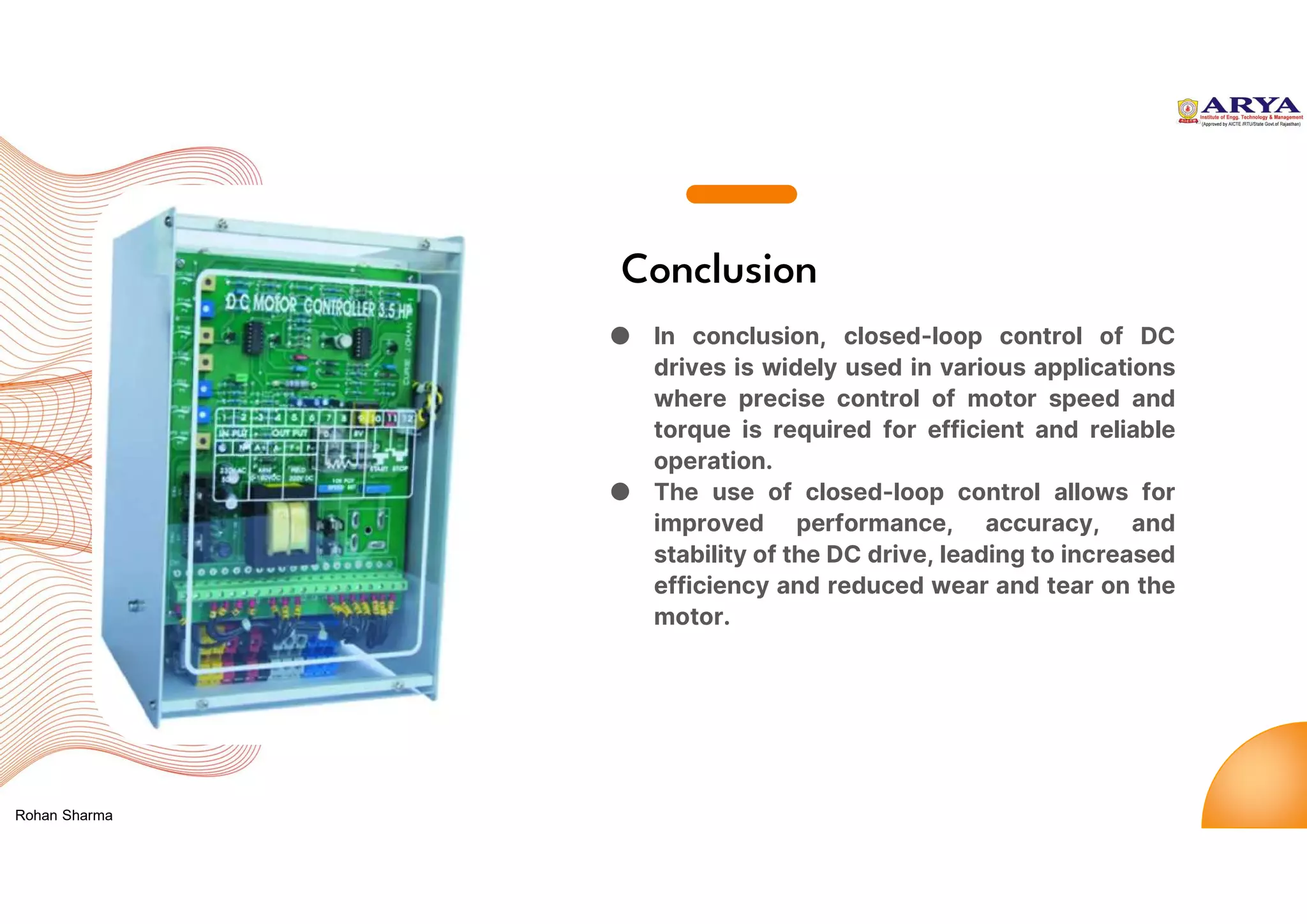
Conclusion
● In conclusion,closed-loop control of DC
drives is widely used in various applications
where precise control of motor speed and
torque is required for efficient and reliable
operation.
● The use of closed-loop control allows for
improved performance, accuracy, and
stability of the DC drive, leading to increased
efficiency and reduced wear and tear on the
motor.
Rohan Sharma