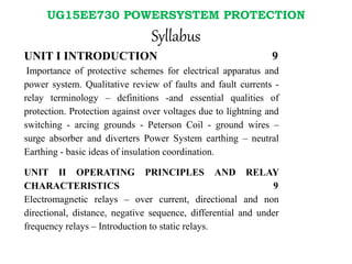
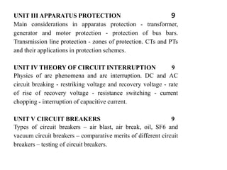
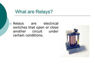
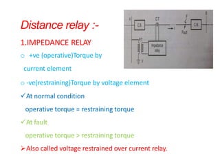
DEPARTMENTS: EEE {semester 07}
Regulation : 2015
Book Reference:
1. Principles of power systems by V.K.Metha
2. Power system engineering by Rajput
3. Switchgear & Protection by Badri Ram
4. Protection & Switchgear by U.A.Bakshi
UG15EE730
POWERSYSTEM PROTECTION
Presented by,
A.Johny Renoald, AP/EEE
VIVEKANANDHA COLLEGE OF ENGINEERING FOR WOMEN
UG15EE730 POWERSYSTEM PROTECTION
Syllabus
UNIT I INTRODUCTION 9
Importance of protective schemes for electrical apparatus and
power system. Qualitative review of faults and fault currents -
relay terminology – definitions -and essential qualities of
protection. Protection against over voltages due to lightning and
switching - arcing grounds - Peterson Coil - ground wires –
surge absorber and diverters Power System earthing – neutral
Earthing - basic ideas of insulation coordination.
UNIT II OPERATING PRINCIPLES AND RELAY
CHARACTERISTICS 9
Electromagnetic relays – over current, directional and non
directional, distance, negative sequence, differential and under
frequency relays – Introduction to static relays.
UNIT III APPARATUS PROTECTION 9
Main considerations in apparatus protection - transformer,
generator and motor protection - protection of bus bars.
Transmission line protection - zones of protection. CTs and PTs
and their applications in protection schemes.
UNIT IV THEORY OF CIRCUIT INTERRUPTION 9
Physics of arc phenomena and arc interruption. DC and AC
circuit breaking - restriking voltage and recovery voltage - rate
of rise of recovery voltage - resistance switching - current
chopping - interruption of capacitive current.
UNIT V CIRCUIT BREAKERS 9
Types of circuit breakers – air blast, air break, oil, SF6 and
vacuum circuit breakers – comparative merits of different circuit
breakers – testing of circuit breakers.
UNIT
2
OPERATING PRINCIPLES AND
RELAY CHARACTERISTICS
UNIT 2 Syllabus
• Electromagnetic relays
• over current relay
• directional relay
• non-directional relay
• distance relay
• negative sequence relay
• differential relay
• under frequency relay
• Introduction to static relays
Relay Overview
What are Relays?
 Relays are electrical
switches that open or close
another circuit under
certain conditions.
Relay Purpose
 Isolate controlling circuit from controlled circuit.
 Control high voltage system with low voltage.
 Control high current system with low current.
 Logic Functions
How a Relay Works
Electromagnetic
Relay
They work on the following two main operating principles :
(i) Electromagnetic attraction
(ii) Electromagnetic induction
Electromagnetic Attraction Relays
(i) Attracted armature type relay
(ii) Solenoid type relay
(iii)Balanced beam type relay
Induction Relays / Electromagnetic
induction
(i) Induction type overcurrent Relay (Non Directional
Relay)
(ii) Induction Cup Relay (Directional Relay)
1. Attracted Armature Type Relays
These have a coil or
electromagnet energized by a
coil .The coil is energized by
operating quantity like V or I.
Under normal conditions
the coil cannot attract the
plunger due to spring force.
Under fault condition the fault
current increases so armature
or plunger gets attracted to
close the contacts .
These have a coilAottrracted Armature Type Relays
electromagnet energized by a
coil .The coil is energized by
operating quantity like V or I.
Under normal conditions the coil
cannot attract the plunger due
to spring force. Under fault
condition the fault current
increases so armature or
plunger gets attracted to close
the contacts .
Attracted Armature Type Relays
Applications
1.For over current protection
2.Differential Protection
3.Auxiliary Relays
4.Definite time lag over current
and earth fault protection
(ii) Solenoid type relay
• It consists of a solenoid and movable iron plunger
arranged as shown.
• Under normal operating conditions, the current
through the relay coil C is such that it holds the
plunger by gravity or spring in the position shown.
• However, on the occurrence of a fault, the current
through the relay coil becomes more than the
pickup value, causing the plunger to be attracted to
the solenoid. The upward movement of the plunger
closes the trip circuit, thus opening the circuit
breaker and disconnecting the faulty circuit.
(iii) Balanced beam type relay
• It consists of an iron armature fastened to a
balance beam. Under normal operating
conditions , the current through the relay coil is
such that the beam is held in the horizontal
position by the spring.
• When a fault occurs, the current through the
relay coil becomes greater than the pickup value
and the beam is attracted to close the trip circuit.
This causes the opening of the circuit breaker to
isolate the faulty circuit.
Balanced beam type relay
Induction cup structure
• It most closely resembles an induction motor, except that
the rotor iron is stationary, only the rotor conductor
portion being free to rotate.
• The moving element is a hollow cylindrical rotor which
turns on its axis. The rotating field is produced by two
pairs of coils wound on four poles as shown.
• The rotating field induces currents in the cup to provide
the necessary driving torque.
• If φ1 and φ2 represent the fluxes produced by the
respective pairs of poles, then torque produced is
proportional to φ1 Φ2 sin α .
• where α is the phase difference between the two fluxes.
A control spring and the back stop for closing of the
contacts carried on an arm are attached to the spindle of
the cup to prevent the continuous rotation.
• Induction cup structures are more efficient torque
producers than either the shaded-pole or the watthour
meter structures. Therefore, this type of relay has very
high speed and may have an operating time less then 0.1
second.
Induction type
overcurrent Relay
(Non Directional Relay)
• This type of relay works on the induction
principle and initiates corrective measures
when current in the circuit exceeds the
predetermined value.
• The actuating source is a current in the
circuit supplied to the relay from a current
transformer. These relays are used on a.c.
circuits only and can operate for fault
current flow in either direction.
Constructional details
It consists of a metallic (aluminium) disc which is free to rotate
in between the poles of two electromagnets. The upper
electromagnet has a primary and a secondary winding. The primary
is connected to the secondary of a C.T. in the line to be protected
and is tapped at intervals. The tappings are connected to a plug-
setting bridge by which the number of active turns on the relay
operating coil can be varied, thereby giving the desired current
setting.
The secondary winding is energized by induction from
primary and is connected in series with the winding on the lower
magnet. The controlling torque is provided by a spiral spring.
The spindle of the disc carries a moving contact which bridges
two fixed contacts (connected to trip circuit) when the disc rotates
through a pre-set angle. This angle can be adjusted to any value
between 0° and 360° . By adjusting this angle, the travel of the
moving contact can be adjusted and hence the relay can be given
any desired time setting.
Operation
 The driving torque on the aluminium disc is set up due to the
induction principle. This torque is opposed by the restraining
torque provided by the spring.
 Under normal operating conditions, restraining torque is
greater than the driving torque produced by the relay coil
current. Therefore, the aluminium disc remains stationary.
 If the current in the protected circuit exceeds the pre-set value,
the driving torque becomes greater than the restraining torque.
Consequently, the disc rotates and the moving contact bridges
the fixed contacts when the disc has rotated through a pre-set
angle. The trip circuit operates the circuit breaker which isolates
the faulty section.
DIRECTIONAL
RELAY
induction relays are two types
directional relaysNon directional
relays
Difference between the two: …………?
• Non directional relays are activated by only current flowing in the circuit
to be protected.
• Directional relays are activated by power flowing in the specific direction.
Hence it requires both current and voltage of the circuit to be protected.
* it requires specific direction of current flow*
DIRECTIONAL POWER RELAY
Constructional details:
It consits of two electro magnets
1) upper magnet which is E- shaped
2) lower magnet which is U- shaped.
The upper maget consits of primary winding on the central limb
which is energised by voltage from secondary of P.T
lower magnet houses secondary winding which is energised by
current of the circuit from secondary of C.T.
Further lower magnet is connected to PSM as previous
case (not shown)
 In between this two electro magnets we have aluminium disc pivoted as shown
 This alumunium disc carries a moving contact which can bridge fixed contact by
rotating though a pre set angle.
 The time of operation depends upon the pre set angle
 Restraining torque is provide by spring which twists in reverse direction.
Operation:
From the diagram we can conclude that we have two flux quantaties: φ1 & φ2 .
Always, φ1 laggs V by 90 0
φ2 inphase with current I
Due to phase difference between two flux quantaties i.e., α = 90-θ
Φ1 α V & φ2 α I
Hence T = φ1 φ2 sinα
= φ1 φ2 sin(90-θ)
= VI COS θ
= POWER
Hence the relay activated only when there is a specific direction of power
flow
when power flows in normal direction both driving torque and
restraining torque twists in same direction and relay does not operates.
when the power flow is in reverse direction, driving torque and restraining
torque acts in opposite direction and relay operates.therefore CB operates
and disconnects faulty section.
DIRECTIONAL OVER CURRENT RELAY:
From the previous discussion
T = V I COS θ
Under abnormal condition
under abnormal conditions voltage in the circuit is too low.
Therefore the driving torque becomes abnormally too small .Hence
the relay does not operate.
ie., the directional power relay is not suitable for short
circuit conditions.
This problem can be overcome by directional over current
relay.
Directional overcurrentrelay:
Directional overcurrent relay makes use of two relays
i) directional power relay
ii) Non directional current relay
( directional element)
(non-directional element)
Construction:
1) Directional element :
It is similar in construction to directional power relay.
 it consists of upper magnet which is E-shaped and carries primary
winding which is excited by voltage of the circuit to be protected through
secondary of PT.
 The lower magnet is U-shaped carries secondary winding which is
excited by current of the circuit to be protected through secondary of CT.
 The secondary winding is extended to lower magnet primary winding as shown.
 The trip contacts 1 & 2 are connected in series with secondary winding of lower
magnet.
therefore for the relay to operate, at first directional element should be
activated first.
2) Non directionalelement:
* It is activated only by current flowing in the circuit*
it is similar in construction to non-directional over current relay.
For this element to operate ,at first directional element should be activated first.
the secondary winding is further connected to PSM( not shown), for current
setting.
Operation :
When short circuit occurs current tend to be reversed .Hence directional element
starts operating and closes the trip contact.
with closing of trip contact, the secondary winding of non directional element
is complete and disc starts rotating. When moving contact bridges fixed contact
the circuit breaker operates and separates the faulty section.
Distance Relay
(mho relay)
Presented by C.GOKUL,AP/EEE ,Velalar College of Engg & Tech , Erode
Distance relay :-
1.IMPEDANCE RELAY
o +ve (operative)Torque by
current element
o -ve(restraining)Torque by voltage element
At normal condition
operative torque = restraining torque
At fault
operative torque > restraining torque
Also called voltage restrained over current relay.
2.reactance relay :-
o Operative Torque by current
o Restraining Torque by Current-Voltage Directional relay
 +ve torque by over current element
 -ve torque by directional unit
Directional element designed for maxi. Torque angle = 90
degree
3.Mho relay :-
Induction cup type structure.
oOperative Torque produced by V & I element.
o Restraining Torque by Voltage element.
Also called Admittance relay.
NEGATIVE SEQUENCE RELAY
 The negative relays are also called phase unbalance
relays because these relays provide protection against
negative sequence component of unbalanced currents
existing due to unbalanced loads or phase- phase
faults.
 The unbalanced currents are dangerous from
generators and motors point of view as these currents
can cause overheating. Negative sequence relays are
generally used to give protection to generators and
motors against unbalancedcurrents.
DIAGRAM:
CONSTRUCTION:
 It consists of aresistance bridge network.
 The magnitudes of the impedances of all the branches
of the network areequal.
 The impedances Z1 and Z3 are purely resistive while the
impedances Z2 and Z4 are the combinations of
resistance and reactance.
 The currents in the branches Z2 and Z4 lag by 60o from
the currents in the branchesZ1 and Z3.
branch B-D consists of inverse time
relay. The relay has negligible
 The vertical
characteristics
impedance.
PHASOR DIAGRAM:
Thecurrent IR getsdivided into two equal parts I1 and I2. And
I2 lags I1 by 60o.
Ī1 + Ī2= Īrs
Let I1 = I2 = I
The perpendicular is drawn from point A on thediagonal
meeting itat point B. This bisects thediagonal.
... OB = IR /2
Now in triangleOAB,
...
cos 30 = OB/OA
√3/2 = (IR/2)/I
... I = IR/√3 = I1 = I2 ............(1)
Now I1 leads IR by 30o while I2 lags IR by 30o.
Similarly the current IB gets divided into two equal parts
I3 and I4. The current I3 lags I4 by 60o. From equation (1) we
can write,
IB /√3 = I3 = I4 ...............(2)
The current I4 leads by IB whilecurrent I3 lags IB by 30o.
The current entering the relay at the junction point B in
the Fig. 1 is thevector sum of , and .
Irelay = Ī1 + Ī3 + ĪY
= IY + (IR/√3) (leads IR by 30o) + IB/√3(lags IBby30o)
 when the load is balanced and no
negative sequence currentsexist.
... Ī1 + Ī3 =-ĪY
Ī1 + Ī3 + ĪY = 0
Thus thecurrententering the relayat point B is zero.
Similarly the resultantcurrentat junction D is also
zero. Thus the relay is inoperative for a balanced
system.
UNDER FAULTY CONDITION:
Now consider that there is unbalanced load on
generator or motor due to which negative sequence
currents exist.
The component I1 and I3 are equal and oppositeto
each other at the junction point B. Hence I1 and
I3 cancel each other. Now the relay coil carries the
current IY and when this current is more than a
predetermined value, the relay trips closing the
contacts of trip circuit which opens the circuit breaker.
ZERO SEQUENCE CURRENT:

 Underzero sequencecurrents the total currentof
twice the zero sequence current flows through the
relay. Hence the relay operates to open the circuit
breaker.
Tomake the relay sensitive to only negative
sequencecurrents by making it inoperativeunder the
influence of zero sequence currents is possible by
connecting the current transformers in delta .Under
delta connection of current transformers, no zero
sequencecurrentcan flow in the network.
Definition
A two-winding relay that operates when the difference
between the currents in the two windings reaches a
predetermined value is called differential relays.
A two-winding relay that operates when the difference
between the currents in the two windings reaches a
predetermined value.
• In case of electrical quantities exceed a predetermined value, a
current differential relay is one that compares the current
entering a section of the system with current leaving the section.
• Under normal operating conditions, the two currents are equal
but as soon as fault occurs, this condition no longer applies. The
difference between the incoming and outgoing currents is
arranged to flow through relay operating coil. If this difference is
equal to or greater than the pick up value the relay will operate
and open the circuit breaker and isolate the faulty section.
• Any type of relay when connected in a particular way can be
made to operate as a differential relay. It is not the relay
construction but the way in which relay is connected in a circuit
makes it a differential relay.
There are three fundamental systems of differential or balanced protection:
I. current differential relay
II. voltage differential relay
III. Biased beam relay or percentage differential relay
(i) Current balance protection
Fig 16 a shows an arrangement of an over current relay connected to operate as a differential
relay. A pair of identical current transfonners is fitted on either end of the section to be
protected (alternator winding in this case). The secondaries of CT’s are connected in series in
such a way that they carry the induced currents in the same direction. The operating coil of
over current relay is connected across the CT secondary circuit. This differential relay
compares the current at the two ends of the alternator winding.
Under normal operating conditions, suppose the alternator winding carries a normal current
of 1000 A. Then the current in the two secondaries of CT’s are equal as in figure. These
currents will merely circulate between the two CT’s and no current will flow through the
differential relay as shown in the diagram fig 16 a. Therefore, the relay remains inoperative.
If a ground fault occurs on the alternator winding as shown in fig 16 b. the two secondary
currents will not be equal and the current flows through the operating coil of the relay,
causing the relay to operate. The amount of current flow through the relay will depend upon
the way the fault is being fed.
Disadvantages
The impedance of the pilot cables generally causes a
slight difference between the currents at the two ends of
the section to be protected, then the small differential
current flowing through the relay may cause it to operate
even under no fault conditions.
Pilot cable capacitance causes incorrect operation of the
relay when a large current flows
Accurate matching of current transformers cannot be
achieved due to pilot circuit impedance
(ii) voltage differential relay
Fig. 18 shows the arrangement of voltage balance
protection.
In this scheme of protection, two similar current
transformers are connected at either end of the element
to be protected (e.g. an alternator winding) by means of
pilot of wires.
The secondaries of current transformers are connected
in series with a relay in such a way that under normal
conditions, their induced e.m.f’s are in opposition
Under healthy conditions, equal currents will flow in
both primary windings. Therefore, the secondary voltages
of the two transformers are balanced against each other
and no current will flow through the relay-operating coil.
When a fault occurs in the protected zone, the currents
in the two primaries will differ from one another and
their secondary voltages will no longer be in balance.
This voltage difference will cause a current to flow
through the operating coil of the relay, which closes the
trip circuit.
Disadvantages
The voltage balance system suffers from the following
drawbacks
 A multi-gap transformer construction is required to
achieve the accurate balance between current
transformer pairs.
The system is suitable for protection of cables of
relatively short, lengths due to the capacitance of pilot
wires.
The biased beam relay also called percentage differential relay is designed to respond to
the differential current in terms of its fractional relation to the current flowing through the
protected section.
It’s called percentage differential relay because the ratio of differential operating current
to average restraining current is a fixed percentage.
It’s called bias relay because restraining known as biased coil produces the bias force. Fig
17 a, shows the schematic arrangements of biased beam relay. It is essentially an over
current balanced beam type relay with an additional restraining coil. The restraining coil
produces a bias force in the opposite direction to the operating force.
III. Biased beam relay or percentage differential relay
Under normal and through load conditions, the bias force
due to restraining coil is greater than operating force.
Therefore, the relay remains inoperative.
When an internal fault occurs, the operating force
exceeds the bias force. Consequently the trip contacts
are closed to open the circuit breaker.
The bias force can be adjusted by varying the
number of turns on the restraining coil.
Introduction
to Static Relay
• The static relay is the next generation relay after
electromechanical type.
• The Solid Static relays was first introduced in
1960’s. The term ‘static’ implies that the
relay has no moving mechanical parts in it.
• Compared to the Electromechanical Relay, the
Solid Static relay has longer life-span, decreased
noise when operates and faster respond speed.
• The static relays have been designed to replace
almost all the functions which were being
achieved earlier by electromechanical relays.
Principle of operation
•
• The essential components of static relays are shown in figure below.
The output of CT and PT are not suitable for static components so
they are brought down to suitable level by auxiliary CT and PT.
Then auxiliary CT output is given to rectifier.
Rectifier rectifies the relaying quantity i.e., the output from a CT or
PT or a Transducer.
• The rectified output is supplied to a measuring
unit comprising of comparators, level detectors,
filters, logic circuits.
• The output is actuated when the dynamic input
(i.e., the relaying quantity) attains the threshold
value. This output of the measuring unit is
amplified by amplifier and fed to the output unit
device, which is usually an electromagnetic one.
• The output unit energizes the trip coil only when
relay operates.
Advantages of Solid State Relay
• Low Weight
• Arc less switching
• Static Relay burden is less than electromagnetic type
of relays. Hence error is less.
• Fast response.
• Long life
• Less power consumption
• More Accurate compared to electromechanical Relay

Protection & switchgear

  • 1.
    DEPARTMENTS: EEE {semester07} Regulation : 2015 Book Reference: 1. Principles of power systems by V.K.Metha 2. Power system engineering by Rajput 3. Switchgear & Protection by Badri Ram 4. Protection & Switchgear by U.A.Bakshi UG15EE730 POWERSYSTEM PROTECTION Presented by, A.Johny Renoald, AP/EEE VIVEKANANDHA COLLEGE OF ENGINEERING FOR WOMEN
  • 2.
    UG15EE730 POWERSYSTEM PROTECTION Syllabus UNITI INTRODUCTION 9 Importance of protective schemes for electrical apparatus and power system. Qualitative review of faults and fault currents - relay terminology – definitions -and essential qualities of protection. Protection against over voltages due to lightning and switching - arcing grounds - Peterson Coil - ground wires – surge absorber and diverters Power System earthing – neutral Earthing - basic ideas of insulation coordination. UNIT II OPERATING PRINCIPLES AND RELAY CHARACTERISTICS 9 Electromagnetic relays – over current, directional and non directional, distance, negative sequence, differential and under frequency relays – Introduction to static relays.
  • 3.
    UNIT III APPARATUSPROTECTION 9 Main considerations in apparatus protection - transformer, generator and motor protection - protection of bus bars. Transmission line protection - zones of protection. CTs and PTs and their applications in protection schemes. UNIT IV THEORY OF CIRCUIT INTERRUPTION 9 Physics of arc phenomena and arc interruption. DC and AC circuit breaking - restriking voltage and recovery voltage - rate of rise of recovery voltage - resistance switching - current chopping - interruption of capacitive current. UNIT V CIRCUIT BREAKERS 9 Types of circuit breakers – air blast, air break, oil, SF6 and vacuum circuit breakers – comparative merits of different circuit breakers – testing of circuit breakers.
  • 4.
  • 6.
    UNIT 2 Syllabus •Electromagnetic relays • over current relay • directional relay • non-directional relay • distance relay • negative sequence relay • differential relay • under frequency relay • Introduction to static relays
  • 7.
  • 8.
    What are Relays? Relays are electrical switches that open or close another circuit under certain conditions.
  • 9.
    Relay Purpose  Isolatecontrolling circuit from controlled circuit.  Control high voltage system with low voltage.  Control high current system with low current.  Logic Functions
  • 10.
  • 11.
    Electromagnetic Relay They work onthe following two main operating principles : (i) Electromagnetic attraction (ii) Electromagnetic induction
  • 12.
    Electromagnetic Attraction Relays (i)Attracted armature type relay (ii) Solenoid type relay (iii)Balanced beam type relay Induction Relays / Electromagnetic induction (i) Induction type overcurrent Relay (Non Directional Relay) (ii) Induction Cup Relay (Directional Relay)
  • 13.
    1. Attracted ArmatureType Relays These have a coil or electromagnet energized by a coil .The coil is energized by operating quantity like V or I. Under normal conditions the coil cannot attract the plunger due to spring force. Under fault condition the fault current increases so armature or plunger gets attracted to close the contacts .
  • 14.
    These have acoilAottrracted Armature Type Relays electromagnet energized by a coil .The coil is energized by operating quantity like V or I. Under normal conditions the coil cannot attract the plunger due to spring force. Under fault condition the fault current increases so armature or plunger gets attracted to close the contacts .
  • 15.
    Attracted Armature TypeRelays Applications 1.For over current protection 2.Differential Protection 3.Auxiliary Relays 4.Definite time lag over current and earth fault protection
  • 16.
    (ii) Solenoid typerelay • It consists of a solenoid and movable iron plunger arranged as shown. • Under normal operating conditions, the current through the relay coil C is such that it holds the plunger by gravity or spring in the position shown. • However, on the occurrence of a fault, the current through the relay coil becomes more than the pickup value, causing the plunger to be attracted to the solenoid. The upward movement of the plunger closes the trip circuit, thus opening the circuit breaker and disconnecting the faulty circuit.
  • 18.
    (iii) Balanced beamtype relay • It consists of an iron armature fastened to a balance beam. Under normal operating conditions , the current through the relay coil is such that the beam is held in the horizontal position by the spring. • When a fault occurs, the current through the relay coil becomes greater than the pickup value and the beam is attracted to close the trip circuit. This causes the opening of the circuit breaker to isolate the faulty circuit.
  • 19.
  • 20.
  • 21.
    • It mostclosely resembles an induction motor, except that the rotor iron is stationary, only the rotor conductor portion being free to rotate. • The moving element is a hollow cylindrical rotor which turns on its axis. The rotating field is produced by two pairs of coils wound on four poles as shown. • The rotating field induces currents in the cup to provide the necessary driving torque.
  • 22.
    • If φ1and φ2 represent the fluxes produced by the respective pairs of poles, then torque produced is proportional to φ1 Φ2 sin α . • where α is the phase difference between the two fluxes. A control spring and the back stop for closing of the contacts carried on an arm are attached to the spindle of the cup to prevent the continuous rotation. • Induction cup structures are more efficient torque producers than either the shaded-pole or the watthour meter structures. Therefore, this type of relay has very high speed and may have an operating time less then 0.1 second.
  • 23.
  • 24.
    • This typeof relay works on the induction principle and initiates corrective measures when current in the circuit exceeds the predetermined value. • The actuating source is a current in the circuit supplied to the relay from a current transformer. These relays are used on a.c. circuits only and can operate for fault current flow in either direction.
  • 26.
    Constructional details It consistsof a metallic (aluminium) disc which is free to rotate in between the poles of two electromagnets. The upper electromagnet has a primary and a secondary winding. The primary is connected to the secondary of a C.T. in the line to be protected and is tapped at intervals. The tappings are connected to a plug- setting bridge by which the number of active turns on the relay operating coil can be varied, thereby giving the desired current setting. The secondary winding is energized by induction from primary and is connected in series with the winding on the lower magnet. The controlling torque is provided by a spiral spring. The spindle of the disc carries a moving contact which bridges two fixed contacts (connected to trip circuit) when the disc rotates through a pre-set angle. This angle can be adjusted to any value between 0° and 360° . By adjusting this angle, the travel of the moving contact can be adjusted and hence the relay can be given any desired time setting.
  • 27.
    Operation  The drivingtorque on the aluminium disc is set up due to the induction principle. This torque is opposed by the restraining torque provided by the spring.  Under normal operating conditions, restraining torque is greater than the driving torque produced by the relay coil current. Therefore, the aluminium disc remains stationary.  If the current in the protected circuit exceeds the pre-set value, the driving torque becomes greater than the restraining torque. Consequently, the disc rotates and the moving contact bridges the fixed contacts when the disc has rotated through a pre-set angle. The trip circuit operates the circuit breaker which isolates the faulty section.
  • 28.
  • 29.
    induction relays aretwo types directional relaysNon directional relays Difference between the two: …………? • Non directional relays are activated by only current flowing in the circuit to be protected. • Directional relays are activated by power flowing in the specific direction. Hence it requires both current and voltage of the circuit to be protected. * it requires specific direction of current flow*
  • 30.
  • 31.
    Constructional details: It consitsof two electro magnets 1) upper magnet which is E- shaped 2) lower magnet which is U- shaped. The upper maget consits of primary winding on the central limb which is energised by voltage from secondary of P.T lower magnet houses secondary winding which is energised by current of the circuit from secondary of C.T. Further lower magnet is connected to PSM as previous case (not shown)
  • 32.
     In betweenthis two electro magnets we have aluminium disc pivoted as shown  This alumunium disc carries a moving contact which can bridge fixed contact by rotating though a pre set angle.  The time of operation depends upon the pre set angle  Restraining torque is provide by spring which twists in reverse direction. Operation: From the diagram we can conclude that we have two flux quantaties: φ1 & φ2 . Always, φ1 laggs V by 90 0 φ2 inphase with current I
  • 33.
    Due to phasedifference between two flux quantaties i.e., α = 90-θ Φ1 α V & φ2 α I Hence T = φ1 φ2 sinα = φ1 φ2 sin(90-θ) = VI COS θ = POWER Hence the relay activated only when there is a specific direction of power flow when power flows in normal direction both driving torque and restraining torque twists in same direction and relay does not operates. when the power flow is in reverse direction, driving torque and restraining torque acts in opposite direction and relay operates.therefore CB operates and disconnects faulty section.
  • 34.
    DIRECTIONAL OVER CURRENTRELAY: From the previous discussion T = V I COS θ Under abnormal condition under abnormal conditions voltage in the circuit is too low. Therefore the driving torque becomes abnormally too small .Hence the relay does not operate. ie., the directional power relay is not suitable for short circuit conditions. This problem can be overcome by directional over current relay.
  • 35.
  • 36.
    Directional overcurrent relaymakes use of two relays i) directional power relay ii) Non directional current relay ( directional element) (non-directional element) Construction: 1) Directional element : It is similar in construction to directional power relay.  it consists of upper magnet which is E-shaped and carries primary winding which is excited by voltage of the circuit to be protected through secondary of PT.  The lower magnet is U-shaped carries secondary winding which is excited by current of the circuit to be protected through secondary of CT.  The secondary winding is extended to lower magnet primary winding as shown.  The trip contacts 1 & 2 are connected in series with secondary winding of lower magnet. therefore for the relay to operate, at first directional element should be activated first.
  • 37.
    2) Non directionalelement: *It is activated only by current flowing in the circuit* it is similar in construction to non-directional over current relay. For this element to operate ,at first directional element should be activated first. the secondary winding is further connected to PSM( not shown), for current setting. Operation : When short circuit occurs current tend to be reversed .Hence directional element starts operating and closes the trip contact. with closing of trip contact, the secondary winding of non directional element is complete and disc starts rotating. When moving contact bridges fixed contact the circuit breaker operates and separates the faulty section.
  • 39.
    Distance Relay (mho relay) Presentedby C.GOKUL,AP/EEE ,Velalar College of Engg & Tech , Erode
  • 40.
    Distance relay :- 1.IMPEDANCERELAY o +ve (operative)Torque by current element o -ve(restraining)Torque by voltage element At normal condition operative torque = restraining torque At fault operative torque > restraining torque Also called voltage restrained over current relay.
  • 43.
    2.reactance relay :- oOperative Torque by current o Restraining Torque by Current-Voltage Directional relay  +ve torque by over current element  -ve torque by directional unit Directional element designed for maxi. Torque angle = 90 degree
  • 46.
    3.Mho relay :- Inductioncup type structure. oOperative Torque produced by V & I element. o Restraining Torque by Voltage element. Also called Admittance relay.
  • 50.
    NEGATIVE SEQUENCE RELAY The negative relays are also called phase unbalance relays because these relays provide protection against negative sequence component of unbalanced currents existing due to unbalanced loads or phase- phase faults.  The unbalanced currents are dangerous from generators and motors point of view as these currents can cause overheating. Negative sequence relays are generally used to give protection to generators and motors against unbalancedcurrents.
  • 51.
  • 52.
    CONSTRUCTION:  It consistsof aresistance bridge network.  The magnitudes of the impedances of all the branches of the network areequal.  The impedances Z1 and Z3 are purely resistive while the impedances Z2 and Z4 are the combinations of resistance and reactance.  The currents in the branches Z2 and Z4 lag by 60o from the currents in the branchesZ1 and Z3. branch B-D consists of inverse time relay. The relay has negligible  The vertical characteristics impedance.
  • 53.
  • 54.
    Thecurrent IR getsdividedinto two equal parts I1 and I2. And I2 lags I1 by 60o. Ī1 + Ī2= Īrs Let I1 = I2 = I The perpendicular is drawn from point A on thediagonal meeting itat point B. This bisects thediagonal. ... OB = IR /2 Now in triangleOAB, ... cos 30 = OB/OA √3/2 = (IR/2)/I ... I = IR/√3 = I1 = I2 ............(1)
  • 55.
    Now I1 leadsIR by 30o while I2 lags IR by 30o. Similarly the current IB gets divided into two equal parts I3 and I4. The current I3 lags I4 by 60o. From equation (1) we can write, IB /√3 = I3 = I4 ...............(2) The current I4 leads by IB whilecurrent I3 lags IB by 30o. The current entering the relay at the junction point B in the Fig. 1 is thevector sum of , and . Irelay = Ī1 + Ī3 + ĪY = IY + (IR/√3) (leads IR by 30o) + IB/√3(lags IBby30o)  when the load is balanced and no negative sequence currentsexist.
  • 56.
    ... Ī1 +Ī3 =-ĪY Ī1 + Ī3 + ĪY = 0 Thus thecurrententering the relayat point B is zero. Similarly the resultantcurrentat junction D is also zero. Thus the relay is inoperative for a balanced system.
  • 57.
    UNDER FAULTY CONDITION: Nowconsider that there is unbalanced load on generator or motor due to which negative sequence currents exist. The component I1 and I3 are equal and oppositeto each other at the junction point B. Hence I1 and I3 cancel each other. Now the relay coil carries the current IY and when this current is more than a predetermined value, the relay trips closing the contacts of trip circuit which opens the circuit breaker.
  • 58.
    ZERO SEQUENCE CURRENT:  Underzero sequencecurrents the total currentof twice the zero sequence current flows through the relay. Hence the relay operates to open the circuit breaker. Tomake the relay sensitive to only negative sequencecurrents by making it inoperativeunder the influence of zero sequence currents is possible by connecting the current transformers in delta .Under delta connection of current transformers, no zero sequencecurrentcan flow in the network.
  • 60.
    Definition A two-winding relaythat operates when the difference between the currents in the two windings reaches a predetermined value is called differential relays. A two-winding relay that operates when the difference between the currents in the two windings reaches a predetermined value.
  • 61.
    • In caseof electrical quantities exceed a predetermined value, a current differential relay is one that compares the current entering a section of the system with current leaving the section. • Under normal operating conditions, the two currents are equal but as soon as fault occurs, this condition no longer applies. The difference between the incoming and outgoing currents is arranged to flow through relay operating coil. If this difference is equal to or greater than the pick up value the relay will operate and open the circuit breaker and isolate the faulty section. • Any type of relay when connected in a particular way can be made to operate as a differential relay. It is not the relay construction but the way in which relay is connected in a circuit makes it a differential relay.
  • 62.
    There are threefundamental systems of differential or balanced protection: I. current differential relay II. voltage differential relay III. Biased beam relay or percentage differential relay (i) Current balance protection Fig 16 a shows an arrangement of an over current relay connected to operate as a differential relay. A pair of identical current transfonners is fitted on either end of the section to be protected (alternator winding in this case). The secondaries of CT’s are connected in series in such a way that they carry the induced currents in the same direction. The operating coil of over current relay is connected across the CT secondary circuit. This differential relay compares the current at the two ends of the alternator winding.
  • 63.
    Under normal operatingconditions, suppose the alternator winding carries a normal current of 1000 A. Then the current in the two secondaries of CT’s are equal as in figure. These currents will merely circulate between the two CT’s and no current will flow through the differential relay as shown in the diagram fig 16 a. Therefore, the relay remains inoperative. If a ground fault occurs on the alternator winding as shown in fig 16 b. the two secondary currents will not be equal and the current flows through the operating coil of the relay, causing the relay to operate. The amount of current flow through the relay will depend upon the way the fault is being fed.
  • 64.
    Disadvantages The impedance ofthe pilot cables generally causes a slight difference between the currents at the two ends of the section to be protected, then the small differential current flowing through the relay may cause it to operate even under no fault conditions. Pilot cable capacitance causes incorrect operation of the relay when a large current flows Accurate matching of current transformers cannot be achieved due to pilot circuit impedance
  • 65.
    (ii) voltage differentialrelay Fig. 18 shows the arrangement of voltage balance protection. In this scheme of protection, two similar current transformers are connected at either end of the element to be protected (e.g. an alternator winding) by means of pilot of wires. The secondaries of current transformers are connected in series with a relay in such a way that under normal conditions, their induced e.m.f’s are in opposition
  • 66.
    Under healthy conditions,equal currents will flow in both primary windings. Therefore, the secondary voltages of the two transformers are balanced against each other and no current will flow through the relay-operating coil. When a fault occurs in the protected zone, the currents in the two primaries will differ from one another and their secondary voltages will no longer be in balance. This voltage difference will cause a current to flow through the operating coil of the relay, which closes the trip circuit.
  • 67.
    Disadvantages The voltage balancesystem suffers from the following drawbacks  A multi-gap transformer construction is required to achieve the accurate balance between current transformer pairs. The system is suitable for protection of cables of relatively short, lengths due to the capacitance of pilot wires.
  • 68.
    The biased beamrelay also called percentage differential relay is designed to respond to the differential current in terms of its fractional relation to the current flowing through the protected section. It’s called percentage differential relay because the ratio of differential operating current to average restraining current is a fixed percentage. It’s called bias relay because restraining known as biased coil produces the bias force. Fig 17 a, shows the schematic arrangements of biased beam relay. It is essentially an over current balanced beam type relay with an additional restraining coil. The restraining coil produces a bias force in the opposite direction to the operating force. III. Biased beam relay or percentage differential relay
  • 69.
    Under normal andthrough load conditions, the bias force due to restraining coil is greater than operating force. Therefore, the relay remains inoperative.
  • 70.
    When an internalfault occurs, the operating force exceeds the bias force. Consequently the trip contacts are closed to open the circuit breaker. The bias force can be adjusted by varying the number of turns on the restraining coil.
  • 71.
  • 72.
    • The staticrelay is the next generation relay after electromechanical type. • The Solid Static relays was first introduced in 1960’s. The term ‘static’ implies that the relay has no moving mechanical parts in it. • Compared to the Electromechanical Relay, the Solid Static relay has longer life-span, decreased noise when operates and faster respond speed. • The static relays have been designed to replace almost all the functions which were being achieved earlier by electromechanical relays.
  • 73.
    Principle of operation • •The essential components of static relays are shown in figure below. The output of CT and PT are not suitable for static components so they are brought down to suitable level by auxiliary CT and PT. Then auxiliary CT output is given to rectifier. Rectifier rectifies the relaying quantity i.e., the output from a CT or PT or a Transducer.
  • 74.
    • The rectifiedoutput is supplied to a measuring unit comprising of comparators, level detectors, filters, logic circuits. • The output is actuated when the dynamic input (i.e., the relaying quantity) attains the threshold value. This output of the measuring unit is amplified by amplifier and fed to the output unit device, which is usually an electromagnetic one. • The output unit energizes the trip coil only when relay operates.
  • 75.
    Advantages of SolidState Relay • Low Weight • Arc less switching • Static Relay burden is less than electromagnetic type of relays. Hence error is less. • Fast response. • Long life • Less power consumption • More Accurate compared to electromechanical Relay