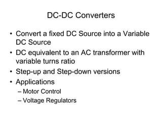
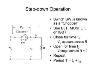
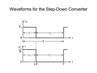
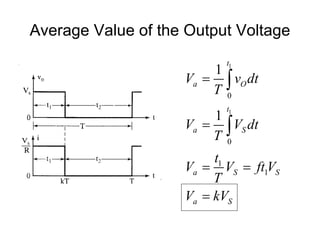
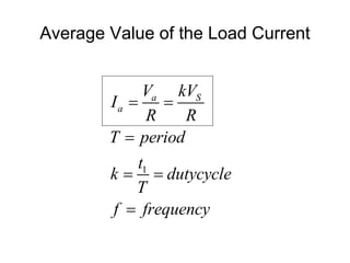
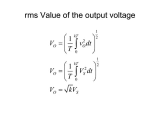
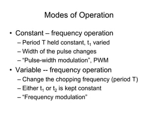
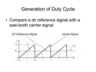
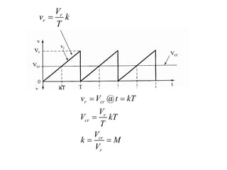
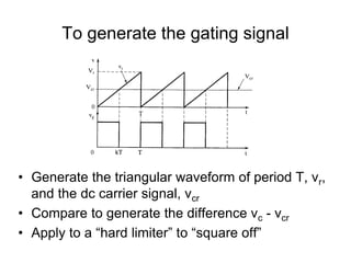
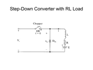
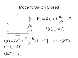
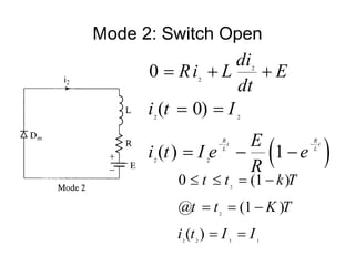
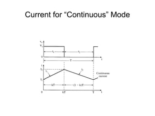
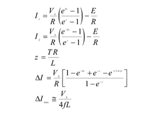
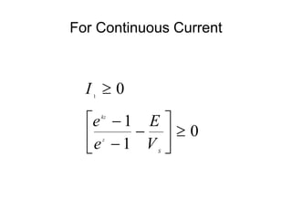
DC- DC Converter
Prepared by,
Mr. A. Johny Renoald M.E., Ph.D.,
DC-DC Converters
• Convert a fixed DC Source into a Variable
DC Source
• DC equivalent to an AC transformer with
variable turns ratio
• Step-up and Step-down versions
• Applications
– Motor Control
– Voltage Regulators
Step-down Operation
• Switch SW is known
as a “Chopper”
• Use BJT, MOSFET,
or IGBT
• Close for time t1
– VS appears across R
• Open for time t2
– Voltage across R = 0
• Repeat
• Period T = t1 + t2
Waveforms for the Step-Down Converter
Average Value of the Output Voltage
1
1
0
0
1
1
1
1
t
a O
t
a S
a S S
a S
V v dt
T
V V dt
T
t
V V ft V
T
V kV


 



Average Value of the Load Current
1
a S
a
V kV
I
R R
T period
t
k dutycycle
T
f frequency
 

 

rms Value of the output voltage
1
2
2
0
1
2
2
0
1
1
kT
O O
kT
O S
O S
V v dt
T
V V dt
T
V kV
 
  
 
 
  
 



If the converter is “lossless”, Pin = Pout
0
2
0
2
2
1
1
1
kT
in O
kT
O
in
S
in
S
in
P v idt
T
v
P dt
T R
V
P kT
T R
V
P k
R






Effective Input Resistance seen by VS
S S
i
S
a
i
V V
R
V
I k
R
R
R
k
 

Modes of Operation
• Constant – frequency operation
– Period T held constant, t1 varied
– Width of the pulse changes
– “Pulse-width modulation”, PWM
• Variable -- frequency operation
– Change the chopping frequency (period T)
– Either t1 or t2 is kept constant
– “Frequency modulation”
Generation of Duty Cycle
• Compare a dc reference signal with a
saw-tooth carrier signal
DC Reference Signal Carrier Signal
r
r
V
v k
T

@
r cr
r
cr
cr
r
v V t kT
V
V kT
T
V
k M
V
 

 
kT
To generate the gating signal
• Generate the triangular waveform of period T, vr,
and the dc carrier signal, vcr
• Compare to generate the difference vc - vcr
• Apply to a “hard limiter” to “square off”
Step-Down Converter with RL Load
Mode 1: Switch Closed
1
1
S
di
V Ri L E
dt
  
 
1 1
( ) 1
R R
t t
L L
S
V E
i t I e e
R
 

   1
( )
t t kT

1 ( 0) 1
( ) t
i t I


1
1 2
( )
t t kT
i kT I
 

Mode 2: Switch Open
 
2
2
2 2
2 2
0
( 0)
( ) 1
R R
t t
L L
di
Ri L E
dt
i t I
E
i t I e e
R
 
  
 
  
2
2
2 2 3 1
0 (1 )
@ (1 )
( )
t t k T
t t K T
i t I I
   
  
 
Current for “Continuous” Mode
 
 
1
2
(1 )
max
1
1
1
1
1
1
4
kz
S
z
kz
S
z
kz z k z
S
z
S
V e E
I
R e R
V e E
I
R e R
T R
z
L
V e e e
I
R e
V
I
fL

   


 


 


  
 
 
 

 
 
1
0
1
0
1
kz
z
S
I
e E
e V

 

 
 

 
For Continuous Current
Define the load emf ratio
1
1
S
kz
z
S
E
x
V
E e
x
V e


 

Vs
220V
J1
1V 0V
XFG1
L
7.5mH
R
5ohm
D2
DIODE_VIRTUAL
Example 5.2
SPICE Results

Unit- 3 DC-DC Converter

  • 1.
    DC- DC Converter Preparedby, Mr. A. Johny Renoald M.E., Ph.D.,
  • 2.
    DC-DC Converters • Converta fixed DC Source into a Variable DC Source • DC equivalent to an AC transformer with variable turns ratio • Step-up and Step-down versions • Applications – Motor Control – Voltage Regulators
  • 3.
    Step-down Operation • SwitchSW is known as a “Chopper” • Use BJT, MOSFET, or IGBT • Close for time t1 – VS appears across R • Open for time t2 – Voltage across R = 0 • Repeat • Period T = t1 + t2
  • 4.
    Waveforms for theStep-Down Converter
  • 5.
    Average Value ofthe Output Voltage 1 1 0 0 1 1 1 1 t a O t a S a S S a S V v dt T V V dt T t V V ft V T V kV       
  • 6.
    Average Value ofthe Load Current 1 a S a V kV I R R T period t k dutycycle T f frequency      
  • 7.
    rms Value ofthe output voltage 1 2 2 0 1 2 2 0 1 1 kT O O kT O S O S V v dt T V V dt T V kV                 
  • 8.
    If the converteris “lossless”, Pin = Pout 0 2 0 2 2 1 1 1 kT in O kT O in S in S in P v idt T v P dt T R V P kT T R V P k R      
  • 9.
    Effective Input Resistanceseen by VS S S i S a i V V R V I k R R R k   
  • 10.
    Modes of Operation •Constant – frequency operation – Period T held constant, t1 varied – Width of the pulse changes – “Pulse-width modulation”, PWM • Variable -- frequency operation – Change the chopping frequency (period T) – Either t1 or t2 is kept constant – “Frequency modulation”
  • 11.
    Generation of DutyCycle • Compare a dc reference signal with a saw-tooth carrier signal DC Reference Signal Carrier Signal
  • 12.
    r r V v k T  @ r cr r cr cr r vV t kT V V kT T V k M V      kT
  • 13.
    To generate thegating signal • Generate the triangular waveform of period T, vr, and the dc carrier signal, vcr • Compare to generate the difference vc - vcr • Apply to a “hard limiter” to “square off”
  • 14.
  • 15.
    Mode 1: SwitchClosed 1 1 S di V Ri L E dt      1 1 ( ) 1 R R t t L L S V E i t I e e R       1 ( ) t t kT  1 ( 0) 1 ( ) t i t I   1 1 2 ( ) t t kT i kT I   
  • 16.
    Mode 2: SwitchOpen   2 2 2 2 2 2 0 ( 0) ( ) 1 R R t t L L di Ri L E dt i t I E i t I e e R           2 2 2 2 3 1 0 (1 ) @ (1 ) ( ) t t k T t t K T i t I I         
  • 17.
  • 18.
        1 2 (1) max 1 1 1 1 1 1 4 kz S z kz S z kz z k z S z S V e E I R e R V e E I R e R T R z L V e e e I R e V I fL                             
  • 19.
    1 0 1 0 1 kz z S I e E e V           For Continuous Current
  • 20.
    Define the loademf ratio 1 1 S kz z S E x V E e x V e     
  • 21.
  • 23.