IRJET- Simulation and Analysis of Five Level SPWM Inverter
•
0 likes•30 views

This document summarizes the simulation and analysis of a five level single phase pulse width modulation (SPWM) inverter. The inverter circuit is divided into three parts: a gate driver circuit to generate control signals by comparing a triangular carrier wave and reference sine wave, the inverter circuit consisting of four IGBTs in an H-bridge configuration, and an external voltage control circuit to vary the collector-emitter voltage of the IGBTs. Simulation results show that a five level inverter produces a multi stepped output voltage waveform and reduces total harmonic distortion compared to a single level inverter, as determined by fast Fourier transform analysis. Higher level inverters could achieve even lower harmonic distortion.

Recommended
Recommended
More Related Content
What's hot
What's hot (20)
Similar to IRJET- Simulation and Analysis of Five Level SPWM Inverter
Similar to IRJET- Simulation and Analysis of Five Level SPWM Inverter (20)
More from IRJET Journal
More from IRJET Journal (20)
Recently uploaded
Recently uploaded (20)
IRJET- Simulation and Analysis of Five Level SPWM Inverter
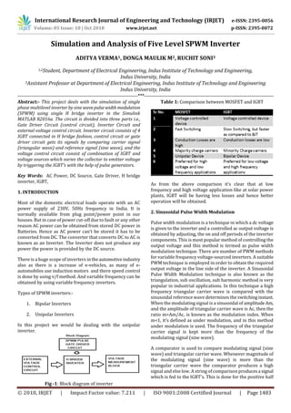
- 1. International Research Journal of Engineering and Technology (IRJET) e-ISSN: 2395-0056 Volume: 05 Issue: 10 | Oct 2018 www.irjet.net p-ISSN: 2395-0072 © 2018, IRJET | Impact Factor value: 7.211 | ISO 9001:2008 Certified Journal | Page 1483 Simulation and Analysis of Five Level SPWM Inverter ADITYA VERMA1, DONGA MAULIK M2, RUCHIT SONI3 1,2Student, Department of Electrical Engineering, Indus Institute of Technology and Engineering, Indus University, India 3Assistant Professor at Department of Electrical Engineering, Indus Institute of Technology and Engineering Indus University, India ---------------------------------------------------------------------***---------------------------------------------------------------------------- Abstract:- This project deals with the simulation of single phase multilevel inverter by sine wavepulsewidth modulation (SPWM) using single H bridge inverter in the Simulink MATLAB R2016a. The circuit is divided into three parts i.e., Gate Driver Circuit (control circuit), Inverter Circuit and external voltage control circuit. Inverter circuit consists of 4 IGBT connected in H bridge fashion, control circuit or gate driver circuit gets its signals by comparing carrier signal (triangular wave) and reference signal (sine wave), and the voltage control circuit consist of combination of IGBT and voltage sources which varies the collector to emitter voltage by triggering the IGBT’s with the help of pulse generators. Key Words: AC Power, DC Source, Gate Driver, H bridge inverter, IGBT, 1. INTRODUCTION Most of the domestic electrical loads operate with an AC power supply of 230V, 50Hz frequency in India. It is normally available from plug point/power point in our houses. But in case of power cut-off due to fault or any other reason AC power can be obtained from stored DC power in Batteries. Hence as AC power can’t be stored it has to be converted from DC. The converter that converts DC to AC is known as an Inverter. The Inverter does not produce any power the power is provided by the DC source. There is a huge scope of inverters intheautomotiveindustry also as there is a increase of e-vehicles, as many of e- automobiles use induction motors and there speed control is done by using v/f method. And variable frequency can be obtained by using variable frequency inverters. Types of SPWM inverters:- 1. Bipolar Inverters 2. Unipolar Inverters In this project we would be dealing with the unipolar inverter. Fig -1: Block diagram of inverter Table 1: Comparison between MOSFET and IGBT As from the above comparison it’s clear that at low frequency and high voltage application like at solar power plants, IGBT will be having less losses and hence better operation will be obtained. 2. Sinusoidal Pulse Width Modulation Pulse width modulation is a technique in which a dc voltage is given to the inverter and a controlled ac output voltage is obtained by adjusting, the on and off periods of the inverter components. This is most popular method of controlling the output voltage and this method is termed as pulse width modulation technique. There are number of PWM methods for variable frequency voltage-sourced inverters. A suitable PWM technique is employed in order to obtain the required output voltage in the line side of the inverter. A Sinusoidal Pulse Width Modulation technique is also known as the triangulation, sub oscillation, sub harmonic method is very popular in industrial applications. In this technique a high frequency triangular carrier wave is compared with the sinusoidal reference wave determines the switchinginstant. When the modulating signal is a sinusoidal of amplitudeAm, and the amplitude of triangular carrier wave is Ac, then the ratio m=Am/Ac, is known as the modulation index. When m<1, it’s defined as under modulation, and in this method under modulation is used. The frequency of the triangular carrier signal is kept more than the frequency of the modulating signal (sine wave). A comparator is used to compare modulating signal (sine wave) and triangular carrier wave. Whenever magnitude of the modulating signal (sine wave) is more than the triangular carrier wave the comparator produces a high signal and else low. A string of comparison producesa signal which is fed to the IGBT’s. This is done for the positive half
- 2. International Research Journal of Engineering and Technology (IRJET) e-ISSN: 2395-0056 Volume: 05 Issue: 10 | Oct 2018 www.irjet.net p-ISSN: 2395-0072 © 2018, IRJET | Impact Factor value: 7.211 | ISO 9001:2008 Certified Journal | Page 1484 cycle and for the negative half cycle, modulating signal (sine wave) is shifted by 180 degree. A not logical operator is used to avoid short circuit of the dc source. The output of the comparison and its logical not is fed to the gate of the IGBT. The potential between theoutput terminals produces sine wave pulse width modulated output. Fig -2: SPWM Generation using comparator 3. Single Level SPWM Inverter Single level SPWM inverter output is obtained by using single dc voltage source. The voltagesourceisappliedacross collector and emitter of the IGBT. Fig -3: SPWM single level inverter Fig -4: Single level SPWM inverter output (t=0.02 sec) (V vs T) Fig -5: Single level SPWM inverter output (t=0.2 sec) (V vs T) 4. Five Level SPWM Inverter In this project, 5 level inverter is made by externally controlling the collector to emitter voltage with the use of IGBT’S and different DC voltage sources. DC voltage sources gets switched through the IGBT’s with the help of pulse generator, this type of results can also be achieved by using digital to analog converter(DAC) interfaced with microcontrollers like arduino. Voltage is varied in the following manner:- Table 2: Time Period of different voltage levels Fig -6: 5 Level SPWM Inverter Circuit
- 3. International Research Journal of Engineering and Technology (IRJET) e-ISSN: 2395-0056 Volume: 05 Issue: 10 | Oct 2018 www.irjet.net p-ISSN: 2395-0072 © 2018, IRJET | Impact Factor value: 7.211 | ISO 9001:2008 Certified Journal | Page 1485 Fig -7: Five level SPWM inverter output (t=0.02 sec) (V vs T) Fig -8: 5 Level SPWM Inverter output (t=0.1sec) (V vs T) The general Fourier series expansion of 5 level inverter is given by 5. Fast Fourier Transform Analysis Fig 9: Single Level SPWM Inverter FFT Analysis Fig 10: Five Level SPWM Inverter FFT Analysis Fast Fourier transform analysis shows that total harmonic distortion (THD) of single level inverteris38.68%andoffive level inverter is 25.52%. 6. Conclusion It can be concluded from the above Fast Fourier transform analysis that, as the level of the inverter increases total harmonic distortion (THD)decreases.Thereforehigherlevel inverters (7 levels, 9 levels and so on) whichcanbedesigned using the same methods will have less total harmonic distortion. Table 3: Time Period of different voltage levels ACKNOWLEDGEMENT This research was supported by our guide Prof. Ruchit Soni. We thank our colleagues from who provided insight and expertise that greatly assisted the research. We also thank our Professors for comments that greatly improved the manuscript. REFERENCES 1. Power Electronics by M.H.Rashid 2. “Power Electronics”, Khanna Publishers,byDr. P.S. Bimbhra.
- 4. International Research Journal of Engineering and Technology (IRJET) e-ISSN: 2395-0056 Volume: 05 Issue: 10 | Oct 2018 www.irjet.net p-ISSN: 2395-0072 © 2018, IRJET | Impact Factor value: 7.211 | ISO 9001:2008 Certified Journal | Page 1486 AUTHORS Aditya Verma is a final year student in Electrical Engineering Department at Indus University, Ahmedabad , India Donga Maulik M is a final year student in Electrical Engineering Department at Indus University Ahmedabad , India Prof. Ruchit Soni is a faculty in Electrical EngineeringDepartment at Indus University Ahmedabad , India