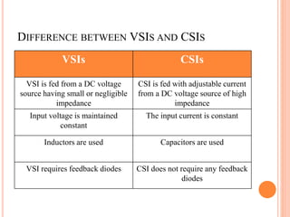
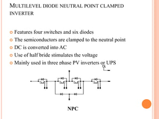
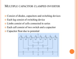
Welcome
Dr.Budhajirao Mulik College Of Agricultural Engineering
And Technology
Mandki-Palvan
Final Seminar
On
Stimulation Of Voltage Source Inverter
Presented By,
Jadhav Preetam Waman
ENMPU150745
POINTS TO BE COVERED
 Introduction
 Types of Inverters
 Types of VSIs
 Control Systems
 Types of Filters
 Modulation Schemes
 Modes of Excitation
 Summery
INTRODUCTION
 Distributed generation is an alternative source
 Sensible solution
 Conversion of DC to AC
 VSIs for commercial as well as industrial purpose
 Smooth and steady waveform
INVERTER
 Types of inverter
 Current source inverter
 Voltage source inverter
 Z-source inverter
DIFFERENCE BETWEEN VSIS AND CSIS
VSIs CSIs
VSI is fed from a DC voltage
source having small or negligible
impedance
CSI is fed with adjustable current
from a DC voltage source of high
impedance
Input voltage is maintained
constant
The input current is constant
Inductors are used Capacitors are used
VSI requires feedback diodes CSI does not require any feedback
diodes
TYPES OF VSIS
 Multilevel diode neutral point clamped inverter
 Multiple capacitor clamped inverter
 Cascaded H-Bridge inverter
 Two level three phase VSIs
 Three phase Four-leg VSIs
MULTILEVEL DIODE NEUTRAL POINT CLAMPED
INVERTER
 Features four switches and six diodes
 The semiconductors are clamped to the neutral point
 DC is converted into AC
 Use of half bride stimulates the voltage
 Mainly used in three phase PV inverters or UPS
NPC
MULTIPLE CAPACITOR CLAMPED INVERTER
 Consist of diodes, capacitors and switching devices
 Each leg consist of switching device
 Limbs consist of cells connected in series
 Each cell consist of two switch and a capacitor
 Capacitor float due to potential
CASCADED H-BRIDGE INVERTER
 Used for single phase as well as three phase inverter
 A H-bridge is used consisting combination of switches
and diodes
 Each cell consist of four switch and four diodes
TWO LEVEL THREE PHASE VSIS
 Coverts DC to AC
 It consist of six switches or MOSFETs
 These are generally connected in grid with output filters
such as LC or LCL filters
THREE PHASE FOUR-LEG VSIS
 Similar as two level three phase VSIs
 Consist of 8 switches or MOSFETs
 An extra leg is introduced from a pair of switch which
acts as a neutral
 These are generally connected in grid with output filters
such as LC or LCL filters
CONTROL SYSTEMS
1. Analog control System
• Representation of time is assumed to have infinite
precision
• Designed without using computers, microcontrollers
or any program
• Capacitors are generally used
• Slow processing speed
2. Digital Control System
• Digital signals are analyzed
• Needs finite precision and extra attention
• Digital controller are implemented
• Relatively easier using software
(IEEE Trans. Power Electron. 2013)
TYPES OF FILTERS
 L - Filter
 LC Filter
 LCL Filter
MODULATION SCHEMES
 Triangular Comparison Based PWM
 Space Vector Based PWM
 Voltage Look-up Table Based PWM
MODES OF EXCITATION
1. 36˚
2. 72˚
3. 108˚
4. 144˚
5. 180˚
6. 216˚
7. 252˚
8. 288˚
9. 324˚
10. 360˚
CONCLUSION
 Several new hybrid topologies can be designed through
the combinations of three main MLI topologies
 PWM strategies that generate switching frequency at
fundamental frequency are also introduced the switching
devices of the higher voltage modules to operate at high
frequencies
REFERENCES
 Blaabjerg et al.(2006) Overview of control and grid
synchronization.
 Liang et al.(2009) four-wire inverters.
 Miret et al.(2013) Control scheme with voltage support
capability.
 M.A Inayathullaah (2014) Stimulation of five phase
inverter
 Patel et al.(1973) Generalized techniques of harmonic
elimination.
 Rodriguez et al.(2002) Multilevel inverters, IEEE Trans.
Ind. Electron
THANK YOU

Voltage Source Inverter

  • 1.
  • 2.
    Dr.Budhajirao Mulik CollegeOf Agricultural Engineering And Technology Mandki-Palvan Final Seminar On Stimulation Of Voltage Source Inverter Presented By, Jadhav Preetam Waman ENMPU150745
  • 3.
    POINTS TO BECOVERED  Introduction  Types of Inverters  Types of VSIs  Control Systems  Types of Filters  Modulation Schemes  Modes of Excitation  Summery
  • 4.
    INTRODUCTION  Distributed generationis an alternative source  Sensible solution  Conversion of DC to AC  VSIs for commercial as well as industrial purpose  Smooth and steady waveform
  • 5.
    INVERTER  Types ofinverter  Current source inverter  Voltage source inverter  Z-source inverter
  • 6.
    DIFFERENCE BETWEEN VSISAND CSIS VSIs CSIs VSI is fed from a DC voltage source having small or negligible impedance CSI is fed with adjustable current from a DC voltage source of high impedance Input voltage is maintained constant The input current is constant Inductors are used Capacitors are used VSI requires feedback diodes CSI does not require any feedback diodes
  • 7.
    TYPES OF VSIS Multilevel diode neutral point clamped inverter  Multiple capacitor clamped inverter  Cascaded H-Bridge inverter  Two level three phase VSIs  Three phase Four-leg VSIs
  • 8.
    MULTILEVEL DIODE NEUTRALPOINT CLAMPED INVERTER  Features four switches and six diodes  The semiconductors are clamped to the neutral point  DC is converted into AC  Use of half bride stimulates the voltage  Mainly used in three phase PV inverters or UPS NPC
  • 9.
    MULTIPLE CAPACITOR CLAMPEDINVERTER  Consist of diodes, capacitors and switching devices  Each leg consist of switching device  Limbs consist of cells connected in series  Each cell consist of two switch and a capacitor  Capacitor float due to potential
  • 10.
    CASCADED H-BRIDGE INVERTER Used for single phase as well as three phase inverter  A H-bridge is used consisting combination of switches and diodes  Each cell consist of four switch and four diodes
  • 11.
    TWO LEVEL THREEPHASE VSIS  Coverts DC to AC  It consist of six switches or MOSFETs  These are generally connected in grid with output filters such as LC or LCL filters
  • 12.
    THREE PHASE FOUR-LEGVSIS  Similar as two level three phase VSIs  Consist of 8 switches or MOSFETs  An extra leg is introduced from a pair of switch which acts as a neutral  These are generally connected in grid with output filters such as LC or LCL filters
  • 13.
    CONTROL SYSTEMS 1. Analogcontrol System • Representation of time is assumed to have infinite precision • Designed without using computers, microcontrollers or any program • Capacitors are generally used • Slow processing speed
  • 14.
    2. Digital ControlSystem • Digital signals are analyzed • Needs finite precision and extra attention • Digital controller are implemented • Relatively easier using software (IEEE Trans. Power Electron. 2013)
  • 15.
  • 16.
  • 17.
  • 18.
    MODULATION SCHEMES  TriangularComparison Based PWM  Space Vector Based PWM  Voltage Look-up Table Based PWM
  • 19.
    MODES OF EXCITATION 1.36˚ 2. 72˚ 3. 108˚ 4. 144˚ 5. 180˚ 6. 216˚ 7. 252˚ 8. 288˚ 9. 324˚ 10. 360˚
  • 20.
    CONCLUSION  Several newhybrid topologies can be designed through the combinations of three main MLI topologies  PWM strategies that generate switching frequency at fundamental frequency are also introduced the switching devices of the higher voltage modules to operate at high frequencies
  • 21.
    REFERENCES  Blaabjerg etal.(2006) Overview of control and grid synchronization.  Liang et al.(2009) four-wire inverters.  Miret et al.(2013) Control scheme with voltage support capability.  M.A Inayathullaah (2014) Stimulation of five phase inverter  Patel et al.(1973) Generalized techniques of harmonic elimination.  Rodriguez et al.(2002) Multilevel inverters, IEEE Trans. Ind. Electron
  • 22.