Torque speed characteristics of Squirrel cage & Slip ring induction motors
•
2 likes•421 views
This video describes the Torque - Slip / Torque- Speed Characteristics of three phase squirrel cage induction motor and slip ring induction motor- also describes the Condition for the maximum torque - Pullout torque and Pullout torque equation
Report
Share
Report
Share
Download to read offline

Recommended
Single Phase Induction Motor Speed Control
This document describes a project to control the speed of a single-phase induction motor. It uses components like op-amps, opto-isolators, SCRs, and a potentiometer. An op-amp operates in comparator mode to generate pulses that trigger SCRs connected in series with the motor. This allows adjusting the firing angle to control motor speed or lamp brightness. Single-phase induction motors are widely used because they are inexpensive and can operate from a single-phase power supply.
Pwm techniques for converters
Pulse-Width Modulation (PWM) techniques are used to control output voltages of power converters. There are three main PWM methods: Sine PWM uses a reference sine wave compared to a triangular carrier wave to generate PWM signals; Hysteresis PWM uses a feedback control loop with variable switching frequency to maintain output within a hysteresis band; Space Vector PWM approximates the reference voltage vector using combinations of the eight switching states and their durations to reduce harmonic distortion and improve voltage utilization.
Motor load dynamics
This document discusses equations governing the dynamics of a motor load system. It defines key terms like moment of inertia (J), angular velocity (ωm), motor torque (T), and load torque (Tl). It explains that during acceleration, the motor supplies the load torque plus an additional torque (Jdωm/dt) to overcome inertia. Load torques can include friction torque (TF), windage torque (Tw), and torque required for useful work (TL). Load torques are classified as either active if they can drive the motor, or passive if they always oppose motion. Different load types can have torque proportional to speed, speed squared, or inversely with speed.
PWM inverter fed VFD
This document discusses control of electrical drives using variable frequency drives (VFDs). It explains how VFDs work by converting alternating current (AC) power to direct current (DC) power using a rectifier, and then converting the DC back to adjustable frequency AC power using an inverter to control motor speed. Diagrams show the block diagram of a VFD and sections including the converter, inverter, and control. The document presents equations showing the relationships between motor speed, frequency, poles and torque. It also describes simulation results showing voltage, current, speed-torque and total harmonic distortion waveforms. In conclusion, it states that VFDs can provide both speed control and energy savings for induction motors.
EXCITATION SYSTEMS
Functions and Performance Requirements
Elements of an Excitation System
Types of Excitation Systems
Control and Protection Functions
Modeling of Excitation Systems
The functions of an excitation system are
to provide direct current to the synchronous generator field winding, and
to perform control and protective functions essential to the satisfactory operation of the power system
The performance requirements of the excitation system are determined by
Generator considerations:
supply and adjust field current as the generator output varies within its continuous capability
respond to transient disturbances with field forcing consistent with the generator short term capabilities:
rotor insulation failure due to high field voltage
rotor heating due to high field current
stator heating due to high VAR loading
heating due to excess flux (volts/Hz)
Power system considerations:
contribute to effective control of system voltage and improvement of system stability
V/F control of Induction Motor - Variable voltage and Variable frequency
This presentation describes Principle of Variable voltage and Variable frequency- the open loop & closed loop Voltage/Frequency (V/F) control of Induction motor with torque speed characteristics -
Motor drives
This document discusses DC motor drives. It provides an overview of DC drives, including their applications, advantages, and types. It describes the basic characteristics and operating modes of shunt, series, and separately excited DC motors, including motoring, regenerative braking, dynamic braking, and plugging modes. It also discusses four quadrant operation of DC motors.
Current Fed Inverters.pptx
The document discusses current-fed inverters that use a constant current source input. It describes two operation modes for inverters - load-commutated and force-commutated, which depend on the thyristor firing angle. Load-commutated mode requires leading power factor load, while force-commutated mode requires lagging VAR load. Self-commutated devices like GTOs allow direct control of the six-step waveform without needing load commutation. However, their use can potentially cause resonance issues between motor inductance and capacitor networks unless PWM is carefully implemented.
Solved Examples for Three - Phase Induction Motors
This document provides solutions to two academic examples involving calculations related to induction motors. The first example calculates motor slip percentage, induced torque, operating speed if torque is doubled, and gross power if torque is doubled for a given induction motor setup. The second example calculates maximum torque, corresponding speed and slip, starting torque, effect of doubling rotor resistance, sketches torque-slip curves, and checks motor stability at different speeds. Review questions are also provided related to torque-speed characteristics, torque development, starting torque control, speed control, maximum torque conditions, full load torque, self-starting behavior, slip never being zero, effects of rotor resistance, reasons for high starting torque, and motors with high starting torque.
Self control of synchronous motor drives
This document discusses using a cycloconverter to provide self-control of a synchronous motor drive. A cycloconverter can directly convert AC power to a variable frequency that can control the speed of AC motors. For synchronous motor drives, cycloconverters are useful because they allow four-quadrant operation and smooth low-speed control with good dynamic response and low harmonic distortion, making them suitable for large, low-speed applications like mills and mine hoists. However, cycloconverters have limitations in that they can only vary the output frequency in steps and not smoothly, and are economically only suitable for high power applications due to their complex control circuitry and high cost.
4.inverter final
The document discusses different types of inverters including their history, applications, classifications, and characteristics. It describes how inverters work by changing DC input to AC output and their uses in applications like UPS, induction heating, electric vehicles. Inverters are classified as static or dynamic based on mobility and as voltage source or current source based on their input/output characteristics. The key aspects of a good inverter are its output waveform quality, efficiency, and reliability.
Inverter
An inverter is a device that converts DC power from batteries into AC power. It allows appliances that run on AC power to operate from a DC power source. There are different types of inverters based on their output waveform: square wave, modified sine wave, and pure sine wave. Square wave inverters are the cheapest but produce a less stable output. Modified sine wave inverters produce a three-step waveform and are suitable for basic appliances. Pure sine wave inverters have the best waveform quality but are the most expensive. Inverters are commonly used in UPS systems, with solar panels, for backup power, and in HVDC transmission.
Load dispatch center
The load dispatch center monitors and controls the power system to ensure reliable power supply. It collects data using a SCADA system and oversees elements like generators, transformers, and transmission lines. The load dispatch center performs economic and secure operation of the power system, and works to restore power lines after faults. It is responsible for functions like load forecasting, outage monitoring, voltage regulation, load scheduling, and coordination between grids.
Excitation system for alternator
This document summarizes different types of excitation systems for alternators. It discusses the function of excitation systems to supply direct current to the field winding and control the voltage and reactive power of alternators. The three main types covered are DC excitation systems, AC excitation systems, and static excitation systems. DC excitation systems use two small DC generators as exciters but are not commonly used for large alternators now. AC excitation systems include brushless and rotating thyristor types and have advantages like eliminating brushes. Static excitation systems have no rotating parts, are suitable for medium and high capacity alternators, and have benefits like smaller size and no windage losses. The document concludes that the selection of an excitation system depends on factors like the altern
Vector Control of AC Induction Motors
Vector control is a more advanced and precise method of controlling AC induction motors compared to scalar control. It involves transforming the motor currents and voltages into a rotating reference frame to obtain decoupled control similar to a DC motor. This allows for independent control of flux and torque for faster dynamic response and better performance than scalar control. The basic implementation of vector control uses Clarke and Park transformations to convert between stationary and rotating reference frames in the controller. It provides DC motor-like precision in speed and torque control of induction motors.
Power system stability
The document discusses power system stability, including classifications of stability (steady state, transient, and dynamic) and factors that affect transient stability. It also covers topics like the swing equation, equal area criterion, critical clearing angle, and multi-machine stability studies. Some key points:
1) Power system stability refers to a system's ability to return to normal operating conditions after disturbances like faults or load changes.
2) Transient stability depends on factors like fault duration and location, generator inertia, and pre-fault loading conditions.
3) The equal area criterion states that a system will remain stable if the accelerating and decelerating area segments on the power-angle curve are equal.
4)
Module 3 electric propulsion electric vehicle technology ppt
The document discusses electric propulsion systems for electric vehicles. It describes how electric motors convert electrical energy to mechanical energy to propel vehicles. Power converters supply electric motors with proper voltage and current, while electronic controllers command the power converter and control motor operation. Common types of electric motors used in electric vehicles include DC motors, induction motors, permanent magnet motors, and switched reluctance motors. The document provides details on the operation and control of these different motor types.
Equivalent circuit of Induction Motor
This presentation describes the per-phase equivalent circuit of induction motor - Power flow diagram - Ratio of air gap power, rotor copper loss and mechanical power developed.
Motor starter
This document discusses different types of motor starters used for AC and DC motors. It describes the necessity of starters to limit inrush current and protect motors. The main types covered are DOL, star-delta, and autotransformer starters. It provides information on their wiring diagrams, motor starting characteristics, advantages and disadvantages, suitable motor sizes and applications. Current ratings for motors used with different starters are also included.
electrical drive
This document discusses electrical drives. It defines an electrical drive as a system that uses an electric motor to control motion for various industrial processes. The key components of an electrical drive system are a power source, power modulator, controller, motor, sensing unit, and mechanical load. The power source provides energy, typically from a 3-phase AC supply. The power modulator interfaces the motor to the power source and provides adjustable voltage, current and frequency. Common types of power modulators include controlled rectifiers, inverters, AC voltage regulators, DC choppers, and cycloconverters. Electrical drives offer advantages like flexible control, easy starting and braking, wide speed and torque ranges, and no exhaust emissions.
INTERVIEW QUESTIONS ON POWER ELECTRONICS BY RAJ
This document provides answers to questions about power electronics components and concepts. It defines terms like holding current, latching current, and turn-on methods for SCRs. It also discusses snubber circuits, firing angle, safe operating area, components for isolating power circuits, current-controlled and voltage-controlled devices, duty cycle, characteristics of ideal op-amps, factors for choosing MOSFETs vs IGBTs, topologies like buck converters, parameters for designing converters, and commutation types. The document provides high-level information on many common topics in power electronics.
Speed Control of Synchronous Motor
Torque Production & Control of Speed in Synchronous Motor.
Speed of synchronous motors can be controlled using two methods called open loop and close loop control.
Open loop contol is the simplest scalar control method where motor speed is controlled by independent frequency control of the converter.
In case of close loop self control mode, instead of controlling the inverter frequency independentaly, the frequency and the phase of the output waveform are controlled by an absolute position encoder mounted on the machine shaft giving an account of position of the rotor.
Electrical Isolation procedure onboard ship
Electricity is a hidden and soundless killer. So, dealing with electricity is inherently hazardous and it is tough to assure that safe working conditions are in place. Undoubtedly, safe electrical isolation is the first prior onboard ship. Both the seafarer and the company have responsibilities to ensure a safe working environment.
Shipboard employees face various problems that can make servicing operations more
challenging, such as:
# Large and complex vessel and vessel machinery, facilities, and systems;
# Machinery, equipment, and systems having multiple power sources, insulating points
and energy types; and
# Difficulty in identifying all energy sources due to faulty engineering drawings and
schematics.
Lead-Acid Battery Simplified Simulink Model using MATLAB
This document describes a simplified Simulink model of a lead-acid battery that can be used to simulate charge and discharge characteristics. The model accounts for battery voltage (Vbat) versus state of charge (SOC) and can simulate charge/discharge times at various current rates. It includes example simulations for a 50Ah battery showing charge time, discharge time waves at different discharge rates, and Vbat vs SOC curves. Instructions are provided on adjusting the model for different battery specifications by editing parameters like capacity and number of cells.
Input output , heat rate characteristics and Incremental cost
This document discusses the input-output, heat rate, and incremental cost characteristics of thermal power plants. It defines input-output characteristics as a plot of fuel input versus power output. Heat rate is the ratio of fuel input to energy output and is the slope of the input-output curve. An incremental fuel rate curve plots the incremental fuel rate, or change in input divided by change in output, versus output. The incremental cost curve multiplies incremental fuel rate by fuel cost to determine incremental cost in monetary terms per unit of output. Economic dispatch of power plants aims to minimize total incremental costs while meeting demand.
Power Electronics interview questions
This document contains 68 questions and answers related to power electronics interview questions. It covers topics like IGBTs, thyristors, power diodes, MOSFETs, BJTs, snubber circuits, choppers, controlled rectifiers, inverters, and PWM control. The questions define key power electronics terms and concepts and discuss the advantages and applications of different power devices and converter topologies.
CSI and vSI fed induction motor drives
This document discusses voltage source inverter (VSI) and current source inverter (CSI) fed induction motor drives. It explains that the torque produced by an induction motor is proportional to the slip at stable operation, and inversely proportional to the slip at unstable operation. It also notes that induction motors should always be operated at or near zero slip for normal operation. The document describes how VSI and CSI topologies work, including using PWM inverters to vary frequency and voltage. It discusses reasons why MOSFET or IGBT devices are preferred over SCRs. In addition, it explains that CSI drives control torque by varying the DC link current to change output voltage.
MARX Generator.pptx
Impulse generators are used to test electrical equipment by generating high voltage surges over short durations, simulating events like lightning strikes. A single-stage impulse generator uses capacitors and resistors to charge then discharge through a spark gap, producing an impulse. However, they are large and inefficient. A Marx generator improves on this design using multiple capacitors charged in parallel and discharged in series, multiplying the output voltage. While more compact and powerful, Marx generators still have long charge times and loss of efficiency due to the charging resistors.
machine design topic 1.0-Shaft-design.pdf
This document discusses shafts, axles, and other rotating machine elements. It provides definitions and key differences between shafts and axles. Shafts are rotating members that transmit power and experience bending, torsional, and axial stresses, while axles are stationary members that support rotating components and only experience bending and axial stresses. The document also covers power transmission equations, stresses in shafts, deflection of shafts, and examples calculating stress and shaft dimensions.
18 me54 turbo machines module 03 question no 6a & 6b
Modal 03: Question Number 5 a & 5 b
i. Reaction Turbine (Parsons’s turbine)
ii. Degree of Reaction for Parsons’s turbine
iii. Condition for maximum utilization factor,
iv. Reaction staging.
v. Numerical Problems.
Previous Year Question papers
More Related Content
What's hot
Solved Examples for Three - Phase Induction Motors
This document provides solutions to two academic examples involving calculations related to induction motors. The first example calculates motor slip percentage, induced torque, operating speed if torque is doubled, and gross power if torque is doubled for a given induction motor setup. The second example calculates maximum torque, corresponding speed and slip, starting torque, effect of doubling rotor resistance, sketches torque-slip curves, and checks motor stability at different speeds. Review questions are also provided related to torque-speed characteristics, torque development, starting torque control, speed control, maximum torque conditions, full load torque, self-starting behavior, slip never being zero, effects of rotor resistance, reasons for high starting torque, and motors with high starting torque.
Self control of synchronous motor drives
This document discusses using a cycloconverter to provide self-control of a synchronous motor drive. A cycloconverter can directly convert AC power to a variable frequency that can control the speed of AC motors. For synchronous motor drives, cycloconverters are useful because they allow four-quadrant operation and smooth low-speed control with good dynamic response and low harmonic distortion, making them suitable for large, low-speed applications like mills and mine hoists. However, cycloconverters have limitations in that they can only vary the output frequency in steps and not smoothly, and are economically only suitable for high power applications due to their complex control circuitry and high cost.
4.inverter final
The document discusses different types of inverters including their history, applications, classifications, and characteristics. It describes how inverters work by changing DC input to AC output and their uses in applications like UPS, induction heating, electric vehicles. Inverters are classified as static or dynamic based on mobility and as voltage source or current source based on their input/output characteristics. The key aspects of a good inverter are its output waveform quality, efficiency, and reliability.
Inverter
An inverter is a device that converts DC power from batteries into AC power. It allows appliances that run on AC power to operate from a DC power source. There are different types of inverters based on their output waveform: square wave, modified sine wave, and pure sine wave. Square wave inverters are the cheapest but produce a less stable output. Modified sine wave inverters produce a three-step waveform and are suitable for basic appliances. Pure sine wave inverters have the best waveform quality but are the most expensive. Inverters are commonly used in UPS systems, with solar panels, for backup power, and in HVDC transmission.
Load dispatch center
The load dispatch center monitors and controls the power system to ensure reliable power supply. It collects data using a SCADA system and oversees elements like generators, transformers, and transmission lines. The load dispatch center performs economic and secure operation of the power system, and works to restore power lines after faults. It is responsible for functions like load forecasting, outage monitoring, voltage regulation, load scheduling, and coordination between grids.
Excitation system for alternator
This document summarizes different types of excitation systems for alternators. It discusses the function of excitation systems to supply direct current to the field winding and control the voltage and reactive power of alternators. The three main types covered are DC excitation systems, AC excitation systems, and static excitation systems. DC excitation systems use two small DC generators as exciters but are not commonly used for large alternators now. AC excitation systems include brushless and rotating thyristor types and have advantages like eliminating brushes. Static excitation systems have no rotating parts, are suitable for medium and high capacity alternators, and have benefits like smaller size and no windage losses. The document concludes that the selection of an excitation system depends on factors like the altern
Vector Control of AC Induction Motors
Vector control is a more advanced and precise method of controlling AC induction motors compared to scalar control. It involves transforming the motor currents and voltages into a rotating reference frame to obtain decoupled control similar to a DC motor. This allows for independent control of flux and torque for faster dynamic response and better performance than scalar control. The basic implementation of vector control uses Clarke and Park transformations to convert between stationary and rotating reference frames in the controller. It provides DC motor-like precision in speed and torque control of induction motors.
Power system stability
The document discusses power system stability, including classifications of stability (steady state, transient, and dynamic) and factors that affect transient stability. It also covers topics like the swing equation, equal area criterion, critical clearing angle, and multi-machine stability studies. Some key points:
1) Power system stability refers to a system's ability to return to normal operating conditions after disturbances like faults or load changes.
2) Transient stability depends on factors like fault duration and location, generator inertia, and pre-fault loading conditions.
3) The equal area criterion states that a system will remain stable if the accelerating and decelerating area segments on the power-angle curve are equal.
4)
Module 3 electric propulsion electric vehicle technology ppt
The document discusses electric propulsion systems for electric vehicles. It describes how electric motors convert electrical energy to mechanical energy to propel vehicles. Power converters supply electric motors with proper voltage and current, while electronic controllers command the power converter and control motor operation. Common types of electric motors used in electric vehicles include DC motors, induction motors, permanent magnet motors, and switched reluctance motors. The document provides details on the operation and control of these different motor types.
Equivalent circuit of Induction Motor
This presentation describes the per-phase equivalent circuit of induction motor - Power flow diagram - Ratio of air gap power, rotor copper loss and mechanical power developed.
Motor starter
This document discusses different types of motor starters used for AC and DC motors. It describes the necessity of starters to limit inrush current and protect motors. The main types covered are DOL, star-delta, and autotransformer starters. It provides information on their wiring diagrams, motor starting characteristics, advantages and disadvantages, suitable motor sizes and applications. Current ratings for motors used with different starters are also included.
electrical drive
This document discusses electrical drives. It defines an electrical drive as a system that uses an electric motor to control motion for various industrial processes. The key components of an electrical drive system are a power source, power modulator, controller, motor, sensing unit, and mechanical load. The power source provides energy, typically from a 3-phase AC supply. The power modulator interfaces the motor to the power source and provides adjustable voltage, current and frequency. Common types of power modulators include controlled rectifiers, inverters, AC voltage regulators, DC choppers, and cycloconverters. Electrical drives offer advantages like flexible control, easy starting and braking, wide speed and torque ranges, and no exhaust emissions.
INTERVIEW QUESTIONS ON POWER ELECTRONICS BY RAJ
This document provides answers to questions about power electronics components and concepts. It defines terms like holding current, latching current, and turn-on methods for SCRs. It also discusses snubber circuits, firing angle, safe operating area, components for isolating power circuits, current-controlled and voltage-controlled devices, duty cycle, characteristics of ideal op-amps, factors for choosing MOSFETs vs IGBTs, topologies like buck converters, parameters for designing converters, and commutation types. The document provides high-level information on many common topics in power electronics.
Speed Control of Synchronous Motor
Torque Production & Control of Speed in Synchronous Motor.
Speed of synchronous motors can be controlled using two methods called open loop and close loop control.
Open loop contol is the simplest scalar control method where motor speed is controlled by independent frequency control of the converter.
In case of close loop self control mode, instead of controlling the inverter frequency independentaly, the frequency and the phase of the output waveform are controlled by an absolute position encoder mounted on the machine shaft giving an account of position of the rotor.
Electrical Isolation procedure onboard ship
Electricity is a hidden and soundless killer. So, dealing with electricity is inherently hazardous and it is tough to assure that safe working conditions are in place. Undoubtedly, safe electrical isolation is the first prior onboard ship. Both the seafarer and the company have responsibilities to ensure a safe working environment.
Shipboard employees face various problems that can make servicing operations more
challenging, such as:
# Large and complex vessel and vessel machinery, facilities, and systems;
# Machinery, equipment, and systems having multiple power sources, insulating points
and energy types; and
# Difficulty in identifying all energy sources due to faulty engineering drawings and
schematics.
Lead-Acid Battery Simplified Simulink Model using MATLAB
This document describes a simplified Simulink model of a lead-acid battery that can be used to simulate charge and discharge characteristics. The model accounts for battery voltage (Vbat) versus state of charge (SOC) and can simulate charge/discharge times at various current rates. It includes example simulations for a 50Ah battery showing charge time, discharge time waves at different discharge rates, and Vbat vs SOC curves. Instructions are provided on adjusting the model for different battery specifications by editing parameters like capacity and number of cells.
Input output , heat rate characteristics and Incremental cost
This document discusses the input-output, heat rate, and incremental cost characteristics of thermal power plants. It defines input-output characteristics as a plot of fuel input versus power output. Heat rate is the ratio of fuel input to energy output and is the slope of the input-output curve. An incremental fuel rate curve plots the incremental fuel rate, or change in input divided by change in output, versus output. The incremental cost curve multiplies incremental fuel rate by fuel cost to determine incremental cost in monetary terms per unit of output. Economic dispatch of power plants aims to minimize total incremental costs while meeting demand.
Power Electronics interview questions
This document contains 68 questions and answers related to power electronics interview questions. It covers topics like IGBTs, thyristors, power diodes, MOSFETs, BJTs, snubber circuits, choppers, controlled rectifiers, inverters, and PWM control. The questions define key power electronics terms and concepts and discuss the advantages and applications of different power devices and converter topologies.
CSI and vSI fed induction motor drives
This document discusses voltage source inverter (VSI) and current source inverter (CSI) fed induction motor drives. It explains that the torque produced by an induction motor is proportional to the slip at stable operation, and inversely proportional to the slip at unstable operation. It also notes that induction motors should always be operated at or near zero slip for normal operation. The document describes how VSI and CSI topologies work, including using PWM inverters to vary frequency and voltage. It discusses reasons why MOSFET or IGBT devices are preferred over SCRs. In addition, it explains that CSI drives control torque by varying the DC link current to change output voltage.
MARX Generator.pptx
Impulse generators are used to test electrical equipment by generating high voltage surges over short durations, simulating events like lightning strikes. A single-stage impulse generator uses capacitors and resistors to charge then discharge through a spark gap, producing an impulse. However, they are large and inefficient. A Marx generator improves on this design using multiple capacitors charged in parallel and discharged in series, multiplying the output voltage. While more compact and powerful, Marx generators still have long charge times and loss of efficiency due to the charging resistors.
What's hot (20)
Solved Examples for Three - Phase Induction Motors
Solved Examples for Three - Phase Induction Motors
Module 3 electric propulsion electric vehicle technology ppt
Module 3 electric propulsion electric vehicle technology ppt
Lead-Acid Battery Simplified Simulink Model using MATLAB
Lead-Acid Battery Simplified Simulink Model using MATLAB
Input output , heat rate characteristics and Incremental cost
Input output , heat rate characteristics and Incremental cost
Similar to Torque speed characteristics of Squirrel cage & Slip ring induction motors
machine design topic 1.0-Shaft-design.pdf
This document discusses shafts, axles, and other rotating machine elements. It provides definitions and key differences between shafts and axles. Shafts are rotating members that transmit power and experience bending, torsional, and axial stresses, while axles are stationary members that support rotating components and only experience bending and axial stresses. The document also covers power transmission equations, stresses in shafts, deflection of shafts, and examples calculating stress and shaft dimensions.
18 me54 turbo machines module 03 question no 6a & 6b
Modal 03: Question Number 5 a & 5 b
i. Reaction Turbine (Parsons’s turbine)
ii. Degree of Reaction for Parsons’s turbine
iii. Condition for maximum utilization factor,
iv. Reaction staging.
v. Numerical Problems.
Previous Year Question papers
Vergara juan proyecto1 movimiento curvilineo normal y tangencial
DIAPOSITIVAS MÁQUINA QUE REALICE MOVIMIENTO CURVILÍNEO: COMPONENTES NORMALES Y TANGENCIALES_Vergara M. Juan S.
Bt044436441
Electronics & Communication Engineering, Computational mathematics, Image processing, Civil Engineering, Structural Engineering, Environmental Engineering, VLSI Testing & Low Power VLSI Design etc.
Appendix E
This document contains calculations for various mechanical, electrical, and computer systems for a device called MARTHA. The calculations are organized by system and include analyses of materials like PVC, steel, aluminum, and various fasteners used. Stress, strain, load, and separation number calculations are shown for components like the chassis, motor mount, screws, and wheels to ensure the design meets strength and safety requirements.
A.C Drives
The document discusses AC motor drives and induction motor drives. It provides details on:
1. AC motor drives are commonly used in industrial and domestic applications due to their light weight, low cost, and low maintenance requirements. Their power control is relatively complex.
2. There are two main types of AC motor drives - induction motor drives and synchronous motor drives. Induction motors are commonly used in adjustable speed drives.
3. Speed control of induction motors can be achieved by varying the stator voltage and frequency. Rotor resistance control using an external resistor is also described for wound rotor induction motors.
Ac/AC conveter
it describes: 1- What is AC/AC Converter and its applilcation?
2- AC Converter in resistive and inductive load with equations
3- using phase control and Time Proportional Control
Gear Trains
This is the basic lecture on gears ( 2nd lecture, please check my 1st lecture) It includes simple gear train, compound gear train and epicyclic gear train. In the end, it includes explanation of analytical method to solve rpms of all the gears in planetery gear system
18 me54 turbo machines module 02 question no 3a & 3b
Module 02: Energy exchange in Turbo machines
Modal 02: Question Number 3 a & 3 b
i. Basic Introduction
ii. Euler’s turbine equation
iii. Alternate form of Euler’s turbine equation
iv. Components of energy transfer
v. Degree of Reaction
vi. Velocity triangles for different values of degree of reaction
vii. Utilization factor
viii. Relation between degree of reaction and Utilization factor
ix. List of Formulas
x. Previous Year Question papers
Coriolis Component numerical
1. The document discusses the velocity and acceleration analysis of a crank and slotted lever quick return motion mechanism.
2. It provides the given data of a crank angle of 60 degrees and crank speed of 100 rpm.
3. It then calculates the velocity and acceleration of the ram (J) as well as the angular acceleration of the slotted lever using graphical methods like velocity diagrams and acceleration diagrams.
2.4 bevel gear
This document discusses bevel gears, which are useful for changing the direction of shaft rotation by 90 degrees. Bevel gears can have straight, spiral, or hypoid teeth and are commonly used in applications like locomotives, marine vessels, automobiles, and industrial machinery. The document explains the components of bevel gears like the pitch cone and cone center. It also discusses how to develop involute teeth on the cone surface of bevel gears. The advantages of bevel gears are also summarized, such as their quiet operation and high efficiency compared to other gear types.
EEE 411 power system stability analysis .pptx
Power system stability refers to the ability of a power system to maintain synchronous operation of generators after experiencing a disturbance such as a fault, load change, or generator loss. There are several types of stability depending on the size of disturbance and time frame. Rotor angle stability concerns maintaining synchronism after small or large disturbances and can be classified as small-signal or transient stability. Transient stability analyzes the ability of the system to maintain synchronism in the seconds after a large disturbance like a fault, using tools like the equal area criterion to determine the critical clearing angle and time.
18 me54 turbo machines module 02 question no 4a & 4b
This document provides information about a course on turbo machines taught by Mr. Thanmay J. S. at VVIET Mysore. The course aims to analyze the energy transfer in radial and axial flow turbo machines using the degree of reaction and utilization factor. It covers general analysis of radial flow compressors and pumps, including velocity triangles and expressions for power, degree of reaction, and the effect of blade discharge angle on performance. It also discusses general analysis of axial flow pumps and compressors, and expressions for degree of reaction and utilization factor in axial flow turbines.
Equations Senior Design Project
The document summarizes the engineering analysis of a senior design project involving a hydraulic lift table. It includes:
1) Governing equations for the hydraulic lift, pistons, lazy susan bearings and shaft stress.
2) Results of calculations showing the hydraulic force required is 4445 pounds to lift the table weighing 222 pounds and bulk pack weighing 45 pounds.
3) The hydraulic pistons must provide over 2200 pounds of force each.
4) Calculations to determine the torque and friction forces on the lazy susan bearing assembly when rotating the table.
Vibration Reduction on Beams Subjected to Moving Loads by Linear and Nonlinea...
Everything about Vibration Reduction on Beams Subjected to Moving Loads by Linear and Nonlinear Vibration Absorbers
Ejercicios resueltos en clase de fundaciones ayudante CALCULO DE ZAPATAS
This document summarizes the design of a rectangular reinforced concrete foundation with the following dimensions: a=4m, b=2m. It includes calculations of dimensions, rebar quantities, bending moments, and shear strength verification. The main steps are:
1) Calculating dimensions based on allowable stress and load
2) Computing bending moments and required rebar areas
3) Sizing rebar and checking spacing requirements
4) Verifying shear strength based on punching shear criteria
The summary provides the essential information about the type of structure designed, key dimensions calculated, and main design checks performed in a concise 3 sentence format.
machine Lecture 6
This document discusses direct current (DC) electrical machines. It covers the equivalent circuit of a DC motor, the magnetization curve of a DC machine, and different types of DC motors including separately excited, shunt, permanent magnet, series, and compounded DC motors. The key characteristics and behaviors of shunt DC motors are analyzed through examples, including the effect of armature reaction and derivation of the torque-speed curve. Nonlinear analysis is also demonstrated for a shunt motor without compensating windings.
Lect 5
This document discusses the absolute thermodynamic temperature scale and the third law of thermodynamics. It shows that connecting heat engines in series results in the temperature of the last engine, Tn, not being able to reach absolute zero. This is because the heat rejected by each subsequent engine, Qn, cannot be zero according to the functional relationship between Qn-1/Qn and Tn-1/Tn, demonstrating that absolute zero cannot be reached on the Kelvin scale without violating the second law of thermodynamics.
Inductionmotorsdtu
3-φ induction motors operate based on the principles of electromagnetic induction. They contain a stationary stator with 3-phase windings connected to a 3-phase power supply. This produces a rotating magnetic field which cuts the rotor conductors and induces current in them. The interaction between the stator and rotor magnetic fields causes the rotor to rotate at a speed slightly less than synchronous speed. The amount the rotor speed is less than synchronous speed is called the slip. Torque characteristics are affected by the rotor resistance. Squirrel cage induction motors are used for fans, pumps and tools, while wound rotor motors are used for cranes and elevators due to their ability to control rotor resistance.
Report
This document provides specifications and calculations for a new 161kV transmission line from Bus 14 Gull to Bus 16 Steel Mill that is 11.68 miles long. It selects a ROBIN conductor based on the current needed by the Steel Mill of 143.44 Amps. It then calculates the impedance, resistance, inductive reactance, and capacitive reactance of the transmission line per mile using the conductor properties. It also calculates the total impedance of 15.258+j10.644 Ohms for the full line and the charging current of 1.406 MVar.
Similar to Torque speed characteristics of Squirrel cage & Slip ring induction motors (20)
18 me54 turbo machines module 03 question no 6a & 6b
18 me54 turbo machines module 03 question no 6a & 6b
Vergara juan proyecto1 movimiento curvilineo normal y tangencial
Vergara juan proyecto1 movimiento curvilineo normal y tangencial
18 me54 turbo machines module 02 question no 3a & 3b
18 me54 turbo machines module 02 question no 3a & 3b
18 me54 turbo machines module 02 question no 4a & 4b
18 me54 turbo machines module 02 question no 4a & 4b
Vibration Reduction on Beams Subjected to Moving Loads by Linear and Nonlinea...
Vibration Reduction on Beams Subjected to Moving Loads by Linear and Nonlinea...
Ejercicios resueltos en clase de fundaciones ayudante CALCULO DE ZAPATAS
Ejercicios resueltos en clase de fundaciones ayudante CALCULO DE ZAPATAS
More from Citharthan Durairaj
Equivalent Circuit, Phasor Diagram, Power Factor Control , V & Inverted V Cur...
This video describes the Equivalent Circuit, Phasor Diagram, Power Factor Control , V & Inverted V Curve of Synchronous Motor
For video please click the below link
https://www.youtube.com/watch?v=GdEAc_IHLbA&t=118s
Closed Loop I-F control using six step current source inverter
This document describes the Closed loop I-F control of Induction motor using six step Current Source Inverter (CSI).
For Explanation video- Please see my you tube channel - Future of EEE
Voltage Source Inverter VSI - Six Step Switching
This presentation describes the Voltage Source Inverter (VSI) - Six Step Switching - Pole voltages and its control - Frequency control of line voltages
Voltage Source Inverter VSI - Pulse Width Modulation (PWM)
This presentation describes the Voltage Source Inverter (VSI) - PWM Operation in Voltage/Frequency (V/F) control of Induction motor
Voltage control of Induction Motor
This presentation describes the
Line Voltage Control - Torque Speed Characteristics - Methods -Advantages - Disadvantages - Applications of Voltage control
Induction Motor- Principle of Operation
This presentation describes the Principle of Operation - Squirrel cage Induction motor
Classification of Induction motors
Rotating Magnetic flux- Relative Motion - Faradays law- Lenz law
Steps to be done in blynk app to get alert notification or email
This presentation describes the
Steps to be done in Blynk App to get alert notification
Steps to be done in Blynk App to get email
Steps to be done in arduino ide for monitoring
This presentation describes the Steps to be done in Arduino IDE & Monitoring the sensor values in blynk app. Program given
Steps to be done in node mcu for monitoring
This Presentation describes the Steps to be done in Node MCU for monitoring LM35 temperature sensor- Connection diagram
Circuit diagram
Steps to be done in blynk app for monitoring
This video describes the monitoring of sensor values/ random values using blynk app and FRED IoT
Steps to be done in Blynk App & Steps to be done in FRED IoT
IoT Introduction
This Presentation describes the
Introduction to IoT - What is IoT ?
An Example - Home automation - Hardware and Software
If you have questions, please don't hesitate to ask in the comment section.
Pls like, share and subscribe. Thank you!
#FutureofEEE
stepper motors
There are three main types of stepper motors: variable reluctance, permanent magnet, and hybrid. Variable reluctance stepper motors use changes in magnetic reluctance to rotate and can be single or multi-stack. They provide high torque but have torque ripple issues. Permanent magnet stepper motors use permanent magnets on the rotor and have bipolar drive circuits. They can achieve a 45 degree step angle through alternate single and two phase excitation. Hybrid stepper motors combine features of variable reluctance and permanent magnet motors, with a 4 pole stator and 5 pole rotor construction. Each motor type has advantages and disadvantages related to torque, torque ripple, and drive circuit complexity.
PMBLDC motors
1) The document discusses permanent magnet brushless DC (PMBLDC) motors and their control. It explains that the desired current waveform for each phase must be estimated based on the instantaneous rotor position to satisfy the maximum torque at minimum current principle.
2) The desired current is provided to the phases through driver circuits containing six transistors, which are switched on based on whether the desired current is positive or negative.
3) Rotor position is typically sensed using three Hall sensors spaced 120 degrees apart, though sensorless control is also possible using back EMF measurements. Control circuit design and operation are also briefly outlined.
Parallel operation of alternators 1
1) For alternators to operate in parallel, they must be synchronized by having equal line voltage, frequency, phase sequence, phase angle, and waveform.
2) When alternators are synchronized and operating in parallel with no load, a circulating current will flow if their speeds or excitations differ slightly.
3) This circulating current acts to resynchronize the alternators by speeding up the slower one and slowing the faster one through their functioning as motor and generator respectively, until steady state is reached with no circulating current.
More from Citharthan Durairaj (14)
Equivalent Circuit, Phasor Diagram, Power Factor Control , V & Inverted V Cur...
Equivalent Circuit, Phasor Diagram, Power Factor Control , V & Inverted V Cur...
Closed Loop I-F control using six step current source inverter
Closed Loop I-F control using six step current source inverter
Voltage Source Inverter VSI - Pulse Width Modulation (PWM)
Voltage Source Inverter VSI - Pulse Width Modulation (PWM)
Steps to be done in blynk app to get alert notification or email
Steps to be done in blynk app to get alert notification or email
Recently uploaded
PROJECT FORMAT FOR EVS AMITY UNIVERSITY GWALIOR.ppt
Ppt on evs amity University project work.........................??????!?!?!?!!?!!?!!?/?/?/?/?/?
CHINA’S GEO-ECONOMIC OUTREACH IN CENTRAL ASIAN COUNTRIES AND FUTURE PROSPECT
The rivalry between prominent international actors for dominance over Central Asia's hydrocarbon
reserves and the ancient silk trade route, along with China's diplomatic endeavours in the area, has been
referred to as the "New Great Game." This research centres on the power struggle, considering
geopolitical, geostrategic, and geoeconomic variables. Topics including trade, political hegemony, oil
politics, and conventional and nontraditional security are all explored and explained by the researcher.
Using Mackinder's Heartland, Spykman Rimland, and Hegemonic Stability theories, examines China's role
in Central Asia. This study adheres to the empirical epistemological method and has taken care of
objectivity. This study analyze primary and secondary research documents critically to elaborate role of
china’s geo economic outreach in central Asian countries and its future prospect. China is thriving in trade,
pipeline politics, and winning states, according to this study, thanks to important instruments like the
Shanghai Cooperation Organisation and the Belt and Road Economic Initiative. According to this study,
China is seeing significant success in commerce, pipeline politics, and gaining influence on other
governments. This success may be attributed to the effective utilisation of key tools such as the Shanghai
Cooperation Organisation and the Belt and Road Economic Initiative.
6th International Conference on Machine Learning & Applications (CMLA 2024)
6th International Conference on Machine Learning & Applications (CMLA 2024) will provide an excellent international forum for sharing knowledge and results in theory, methodology and applications of on Machine Learning & Applications.
22CYT12-Unit-V-E Waste and its Management.ppt
Introduction- e - waste – definition - sources of e-waste– hazardous substances in e-waste - effects of e-waste on environment and human health- need for e-waste management– e-waste handling rules - waste minimization techniques for managing e-waste – recycling of e-waste - disposal treatment methods of e- waste – mechanism of extraction of precious metal from leaching solution-global Scenario of E-waste – E-waste in India- case studies.
Advanced control scheme of doubly fed induction generator for wind turbine us...
This paper describes a speed control device for generating electrical energy on an electricity network based on the doubly fed induction generator (DFIG) used for wind power conversion systems. At first, a double-fed induction generator model was constructed. A control law is formulated to govern the flow of energy between the stator of a DFIG and the energy network using three types of controllers: proportional integral (PI), sliding mode controller (SMC) and second order sliding mode controller (SOSMC). Their different results in terms of power reference tracking, reaction to unexpected speed fluctuations, sensitivity to perturbations, and resilience against machine parameter alterations are compared. MATLAB/Simulink was used to conduct the simulations for the preceding study. Multiple simulations have shown very satisfying results, and the investigations demonstrate the efficacy and power-enhancing capabilities of the suggested control system.
Recycled Concrete Aggregate in Construction Part III
Using recycled concrete aggregates (RCA) for pavements is crucial to achieving sustainability. Implementing RCA for new pavement can minimize carbon footprint, conserve natural resources, reduce harmful emissions, and lower life cycle costs. Compared to natural aggregate (NA), RCA pavement has fewer comprehensive studies and sustainability assessments.
[JPP-1] - (JEE 3.0) - Kinematics 1D - 14th May..pdf
Kinematics 11th jpp- 01. ( Solved ) unacademy namo kaul on 14th may...
bank management system in java and mysql report1.pdf
truth is high but higher still is truth full living
DfMAy 2024 - key insights and contributions
We have compiled the most important slides from each speaker's presentation. This year’s compilation, available for free, captures the key insights and contributions shared during the DfMAy 2024 conference.
Design and Analysis of Algorithms-DP,Backtracking,Graphs,B&B
Dynamic Programming
Backtracking
Techniques for Graphs
Branch and Bound
Recently uploaded (20)
PROJECT FORMAT FOR EVS AMITY UNIVERSITY GWALIOR.ppt
PROJECT FORMAT FOR EVS AMITY UNIVERSITY GWALIOR.ppt
CHINA’S GEO-ECONOMIC OUTREACH IN CENTRAL ASIAN COUNTRIES AND FUTURE PROSPECT
CHINA’S GEO-ECONOMIC OUTREACH IN CENTRAL ASIAN COUNTRIES AND FUTURE PROSPECT
6th International Conference on Machine Learning & Applications (CMLA 2024)
6th International Conference on Machine Learning & Applications (CMLA 2024)
Advanced control scheme of doubly fed induction generator for wind turbine us...
Advanced control scheme of doubly fed induction generator for wind turbine us...
Recycled Concrete Aggregate in Construction Part III
Recycled Concrete Aggregate in Construction Part III
[JPP-1] - (JEE 3.0) - Kinematics 1D - 14th May..pdf
[JPP-1] - (JEE 3.0) - Kinematics 1D - 14th May..pdf
ACRP 4-09
Risk Assessment Method to Support Modification of Airfield Separat...
ACRP 4-09
Risk Assessment Method to Support Modification of Airfield Separat...
bank management system in java and mysql report1.pdf
bank management system in java and mysql report1.pdf
Design and Analysis of Algorithms-DP,Backtracking,Graphs,B&B
Design and Analysis of Algorithms-DP,Backtracking,Graphs,B&B
Tutorial for 16S rRNA Gene Analysis with QIIME2.pdf
Tutorial for 16S rRNA Gene Analysis with QIIME2.pdf
Torque speed characteristics of Squirrel cage & Slip ring induction motors
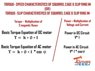
- 1. TORQUE- SPEED CHARACTERISTICS OF SQUIRREL CAGE & SLIP RING IM (OR) TORQUE- SLIP CHARACTERISTICS OF SQUIRREL CAGE & SLIP RING IM Basic Torque Equation of DC motor 𝐓 = 𝐤 ∗ ∅ ∗ 𝐈 Basic Torque Equation of AC motor 𝐓 = 𝐤 ∗ ∅ ∗ 𝐈 * cos Power in DC Circuit V* I Power in AC Circuit V* I * cos Torque - Multiplication of 2 magnetic fluxes Power – Multiplication of Voltage and Current
- 2. Torque Equation of AC Induction Motor 𝐓 = 𝐊 ∗ ∅ ∗ 𝐄 𝟐 𝐙 𝟐 ∗ 𝐑 𝟐 𝐙 𝟐 𝐓 = 𝐤 ∗ ∅ ∗ 𝐈 𝟐* cos 𝐓 = 𝐊 ∗ ∅ ∗ 𝐄 𝟐 ∗ 𝐑 𝟐 𝐙 𝟐 𝟐 𝐓 = 𝐊 ∗ ∅ ∗ 𝐄 𝟐 ∗ 𝐑 𝟐 𝐑 𝟐 𝟐 + 𝐗 𝟐 𝟐 𝐓 = 𝐊 ∗ ∅ ∗ 𝐒 𝐄 𝟐 ∗ 𝐑 𝟐 𝐑 𝟐 𝟐 + ( ሻ𝐒 𝐗 𝟐 𝟐 Slip speed (SNs) = Ns- N 𝐈 𝟐 = 𝐄 𝟐 𝐙 𝟐 ; 𝐂𝐨𝐬𝛗 = 𝐑 𝟐 𝐙 𝟐 𝒁 𝟐 = 𝑹 𝟐 𝟐 + 𝑿 𝟐 𝟐
- 3. 𝐓 ∝ 𝐊 ∗ ∅ ∗ 𝐒 𝐄 𝟐 ∗ 𝐑 𝟐 𝐑 𝟐 𝟐 𝐓 = 𝐊 ∗ ∅ ∗ 𝐒𝐄 𝟐 ∗ 𝐑 𝟐 𝐑 𝟐 𝟐 + ( ሻ𝐒𝐗 𝟐 𝟐 𝐓 ∝ 𝐊 ∗ ∅ ∗ 𝐒𝐄 𝟐 ∗ 𝐑 𝟐 ൫ ሻ𝐒𝐗 𝟐 𝟐 𝐓 ∝ 𝐊 ∗ ∅ ∗ 𝐄 𝟐 ∗ 𝐑 𝟐 𝐒 ∗ 𝐗 𝟐 𝟐 SLIP TORQUE 01 0 Ns SPEED Low SlipHigh Slip LOW SLIP REGION HIGH SLIP REGION Min speed N= 0 @ which slip S = 1 Max speed N= Ns @ which slip S = 0 Starting Torque Critical Slip Pull out Torque (𝐒𝐗 𝟐ሻ 𝟐 ≪ 𝐑 𝟐 𝟐 (𝐒𝐗 𝟐ሻ 𝟐 ≫ 𝐑 𝟐 𝟐 General Torque Equation
- 4. Slip ring Induction Motor (or) Torque –Speed characteristics of Slip ring Induction motor Decreasing Increasing 𝐓 ∝ 𝟏 𝑹 𝐓 ∝ 𝐑
- 5. What is the Condition for Maximum Torque? 𝐝𝐓 𝐝𝐒 = 𝟎 𝐝 𝐝𝐬 𝐊 ∗ ∅ ∗ 𝐒𝐄 𝟐 ∗ 𝐑 𝟐 𝐑 𝟐 𝟐 + ( ሻ𝐒𝐗 𝟐 𝟐 = 𝟎 ൯( 𝐑 𝟐 𝟐 + ሻ𝐒𝐗 𝟐 𝟐 ∗ (𝐊 ∗ ∅ ∗ 𝐄 𝟐 ∗ 𝐑 𝟐ሻ − 𝐊 ∗ ∅ ∗ 𝐒𝐄 𝟐 ∗ 𝐑 𝟐 ∗ (𝟐𝐒𝐗 𝟐 𝟐 𝑹 𝟐 𝟐 + 𝑺 𝟐 𝑿 𝟐 𝟐 𝟐 = 𝟎 V U’ U V’ 𝐕 𝟐 _
- 6. 𝐊 ∗ ∅ ∗ 𝐄 𝟐 ∗ 𝐑 𝟐 𝟑 + 𝐊 ∗ ∅ ∗ 𝐄 𝟐 ∗ 𝐑 𝟐 ∗ 𝐒 𝟐 𝐗 𝟐 𝟐 − 𝐊 ∗ ∅ ∗ 𝐒𝐄 𝟐 ∗ 𝐑 𝟐 ∗ 𝟐𝐒𝐗 𝟐 𝟐 = 𝟎 𝐊 ∗ ∅ ∗ 𝐄 𝟐 ∗ 𝐑 𝟐 (𝐑 𝟐 𝟐 + 𝐒 𝟐 𝐗 𝟐 𝟐 − 𝟐𝐒 𝟐 𝐗 𝟐 𝟐 ሻ = 𝟎 𝐑 𝟐 𝟐 − 𝐒 𝟐 𝐗 𝟐 𝟐 = 𝟎 𝐒 𝟐 = 𝐑 𝟐 𝟐 𝐗 𝟐 𝟐 𝐒 = 𝐑 𝟐 𝐗 𝟐 CRITICAL SLIP = 𝐑 𝟐 𝐗 𝟐 ൯( 𝐑 𝟐 𝟐 + ሻ𝐒𝐗 𝟐 𝟐 ∗ (𝐊 ∗ ∅ ∗ 𝐄 𝟐 ∗ 𝐑 𝟐ሻ − 𝐊 ∗ ∅ ∗ 𝐒𝐄 𝟐 ∗ 𝐑 𝟐 ∗ (𝟐𝐒𝐗 𝟐 𝟐 𝑹 𝟐 𝟐 + 𝑺 𝟐 𝑿 𝟐 𝟐 𝟐 = 𝟎
- 7. 𝐓 = 𝐊 ∗ ∅ ∗ 𝐒𝐄 𝟐 ∗ 𝐑 𝟐 𝐑 𝟐 𝟐 + ( ሻ𝐒𝐗 𝟐 𝟐 𝐓(𝐦𝐚𝐱ሻ = 𝐊 ∗ ∅ ∗ 𝐑2 𝐗2 𝐄2 ∗ 𝐑2 𝐑2 2 + 𝐑2 2 𝐗2 2 ∗ 𝐗2 2 𝐓(𝐦𝐚𝐱ሻ = 𝐊 ∗ ∅ ∗ 𝐄2 ∗ 𝐑2 2 2𝐑2 2 ∗ 𝑿2 𝐓 𝐦𝐚𝐱 𝐨𝐫 𝐩𝐮𝐥𝐥𝐨𝐮𝐭 𝐭𝐨𝐫𝐪𝐮𝐞 = 𝐊 ∗ ∅ ∗ 𝐄 𝟐 𝟐 𝑿 𝟐 PULL OUT TORQUE EQUATION (Irrespective of rotor resistance 𝐑 𝟐)