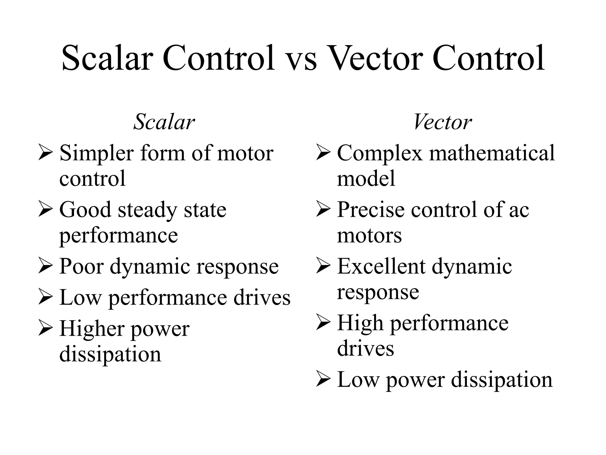
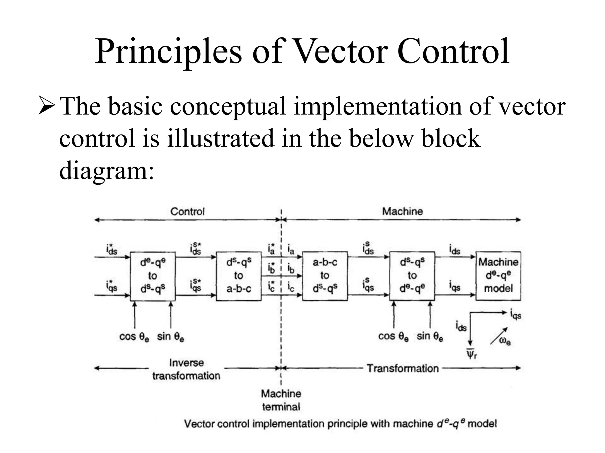
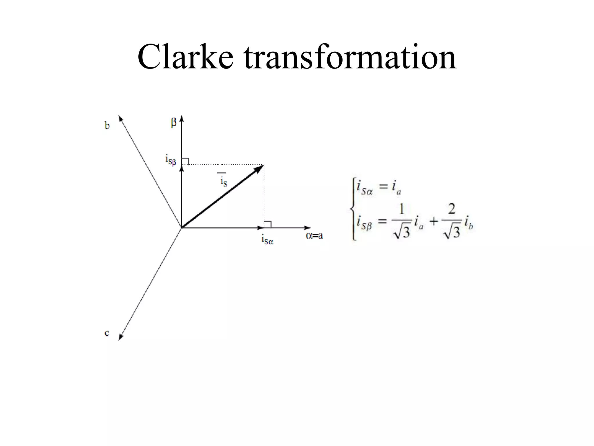
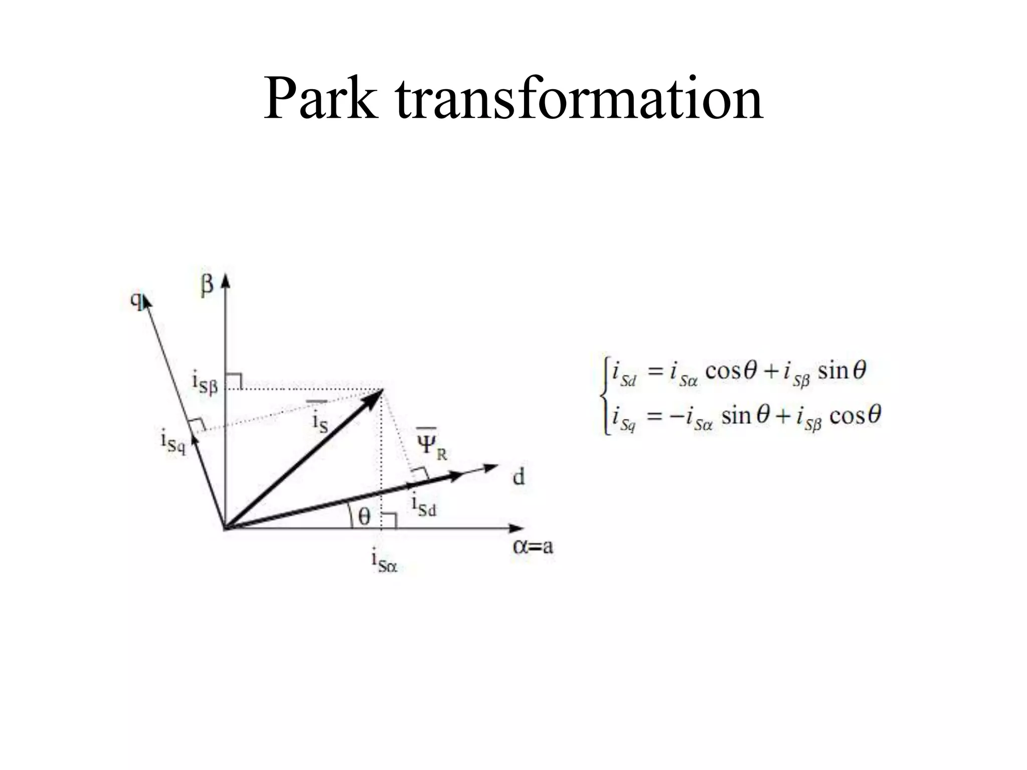
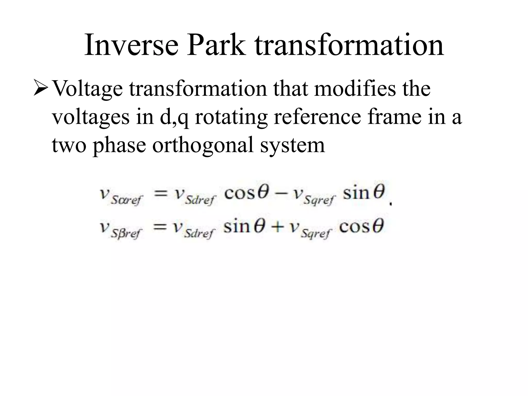
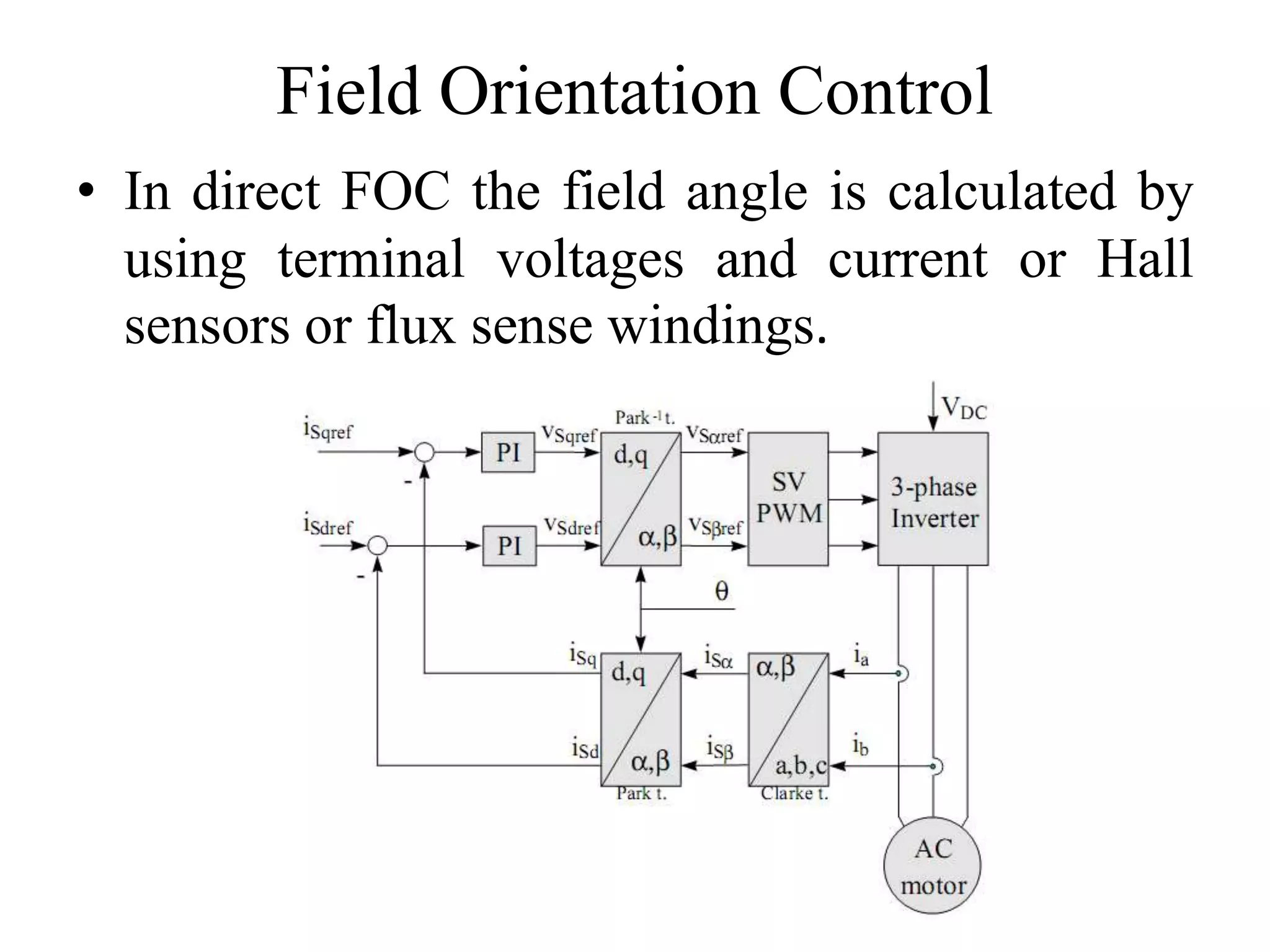
Vector Control of Induction Motors
Pranjal Barman
Research Scholar
Department of Electronics and Communication
Engineering
Tezpur University
Two control approaches of AC drives
Scalar Control : Scalar control is the term used to
describe a simpler form of AC motor control.
Controlled by the adjustable magnitude of stator
voltages and frequency in such a way that the air
gap flux is always maintained at the desired value
at the steady-state
Vector Control : The machine current and voltage
space vectors, the transformation of a 3 phase
speed and time dependent system into a two co-
ordinate time invariant system and effective
PWM pattern generation
Scalar Control vs Vector Control
Scalar
 Simpler form of motor
control
 Good steady state
performance
 Poor dynamic response
 Low performance drives
 Higher power
dissipation
Vector
 Complex mathematical
model
 Precise control of ac
motors
 Excellent dynamic
response
 High performance
drives
 Low power dissipation
Analogy with DC motor control
There is a close parallel between torque
control of a DC motor and vector control of an
AC motor.
The DC motor field flux produced by field
current is orthogonal to the armature flux
produced by the armature current . Because the
vectors are orthogonal, they are decoupled, i.e.
the field current only controls the field flux
and the armature current only controls the
armature flux.
Analogy with DC motor control
DC motor-like performance can be achieved
with an induction motor if the motor control is
considered in the synchronously rotating
reference frame (de-qe) where the sinusoidal
variables appear as dc quantities in steady
state.
With vector control:
ids (induction motor)  If (dc motor)
iqs (induction motor)  Ia (dc motor)
Principles of Vector Control
The basic conceptual implementation of vector
control is illustrated in the below block
diagram:
Principles of Vector Control
The motor phase currents, ia, ib and ic are
converted to ids
s and iqs
s in the stationary
reference frame.
These are then converted to the synchronously
rotating reference frame d-q currents, ids and iqs.
 In the controller two inverse transforms are
performed:
1) From the synchronous d-q to the
stationary d-q reference frame;
2) From d*-q* to a*, b*, c*.
Time invariant coordinate transform
(a,b,c)⇒(α,β) (the Clarke transformation)
which outputs a two co-ordinate time variant
system
(α,β)⇒(d,q) (the Park transformation) which
outputs a two co-ordinate time invariant
system
Clarke transformation
Park transformation
Inverse Park transformation
Voltage transformation that modifies the
voltages in d,q rotating reference frame in a
two phase orthogonal system
Vector control types
There are two approaches to vector control:
1) Direct field oriented current control
- here the rotation angle of the iqs
e vector with
respect to the stator flux is being directly
determined (e.g. by measuring air gap flux)
2) Indirect field oriented current control
- here the rotor angle is being measured
indirectly, such as by measuring slip speed
Field Orientation Control
• In direct FOC the field angle is calculated by
using terminal voltages and current or Hall
sensors or flux sense windings.
Salient Features of Vector Control
Transient response will be fast because torque
control by iqs does not affect flux.
Vector control allows for speed control in all
four quadrants (without additional control
elements
Automatically limits operation to the stable
region.
Space Vector PWM
Inverter switches are driven with two
complementary pulsed signals, providing care
is taken to ensure that there is no overlap in the
power switch transitions.
SVPWM is a technique for generating such
pulsed signals
Minimizes the harmonic contents
These eight switch
combinations determine
eight phase voltage
configurations
The vectors divide the
plan into six sectors
The binary
representations of two
adjacent basic vectors
differ in only one bit
SVPWM, vectors and sectors
Conclusion
Vector control/FOC used in high performance
drives where oscillations in air gap flux linkages
are intolerable, e.g. robotic actuators, centrifuges,
servos, etc.
Field Orientated Controlled AC machines thus
obtain every DC machine advantage
Since high computational power silicon devices,
came to market it has been possible to realize far
more precise digital vector control algorithms
More computational effort and high speed
processors are suitable
References
1. “Field Orientated Control of 3-Phase AC-Motors”;
Literature Number: BPRA073,Texas Instruments
Europe, February 1998
2. “Comparison of scalar and vector control strategies
of Induction Motors”; G.Kohlrusz, D.Fodor
3. “Scalar (V/f) Control of 3-Phase Induction Motors”;
Application Report SPRABQ8–July 2013
Thank You

Vector Control of AC Induction Motors

  • 1.
    Vector Control ofInduction Motors Pranjal Barman Research Scholar Department of Electronics and Communication Engineering Tezpur University
  • 2.
    Two control approachesof AC drives Scalar Control : Scalar control is the term used to describe a simpler form of AC motor control. Controlled by the adjustable magnitude of stator voltages and frequency in such a way that the air gap flux is always maintained at the desired value at the steady-state Vector Control : The machine current and voltage space vectors, the transformation of a 3 phase speed and time dependent system into a two co- ordinate time invariant system and effective PWM pattern generation
  • 3.
    Scalar Control vsVector Control Scalar  Simpler form of motor control  Good steady state performance  Poor dynamic response  Low performance drives  Higher power dissipation Vector  Complex mathematical model  Precise control of ac motors  Excellent dynamic response  High performance drives  Low power dissipation
  • 4.
    Analogy with DCmotor control There is a close parallel between torque control of a DC motor and vector control of an AC motor. The DC motor field flux produced by field current is orthogonal to the armature flux produced by the armature current . Because the vectors are orthogonal, they are decoupled, i.e. the field current only controls the field flux and the armature current only controls the armature flux.
  • 5.
    Analogy with DCmotor control DC motor-like performance can be achieved with an induction motor if the motor control is considered in the synchronously rotating reference frame (de-qe) where the sinusoidal variables appear as dc quantities in steady state. With vector control: ids (induction motor)  If (dc motor) iqs (induction motor)  Ia (dc motor)
  • 6.
    Principles of VectorControl The basic conceptual implementation of vector control is illustrated in the below block diagram:
  • 7.
    Principles of VectorControl The motor phase currents, ia, ib and ic are converted to ids s and iqs s in the stationary reference frame. These are then converted to the synchronously rotating reference frame d-q currents, ids and iqs.  In the controller two inverse transforms are performed: 1) From the synchronous d-q to the stationary d-q reference frame; 2) From d*-q* to a*, b*, c*.
  • 8.
    Time invariant coordinatetransform (a,b,c)⇒(α,β) (the Clarke transformation) which outputs a two co-ordinate time variant system (α,β)⇒(d,q) (the Park transformation) which outputs a two co-ordinate time invariant system
  • 9.
  • 10.
  • 11.
    Inverse Park transformation Voltagetransformation that modifies the voltages in d,q rotating reference frame in a two phase orthogonal system
  • 12.
    Vector control types Thereare two approaches to vector control: 1) Direct field oriented current control - here the rotation angle of the iqs e vector with respect to the stator flux is being directly determined (e.g. by measuring air gap flux) 2) Indirect field oriented current control - here the rotor angle is being measured indirectly, such as by measuring slip speed
  • 13.
    Field Orientation Control •In direct FOC the field angle is calculated by using terminal voltages and current or Hall sensors or flux sense windings.
  • 14.
    Salient Features ofVector Control Transient response will be fast because torque control by iqs does not affect flux. Vector control allows for speed control in all four quadrants (without additional control elements Automatically limits operation to the stable region.
  • 15.
    Space Vector PWM Inverterswitches are driven with two complementary pulsed signals, providing care is taken to ensure that there is no overlap in the power switch transitions. SVPWM is a technique for generating such pulsed signals Minimizes the harmonic contents
  • 16.
    These eight switch combinationsdetermine eight phase voltage configurations The vectors divide the plan into six sectors The binary representations of two adjacent basic vectors differ in only one bit SVPWM, vectors and sectors
  • 17.
    Conclusion Vector control/FOC usedin high performance drives where oscillations in air gap flux linkages are intolerable, e.g. robotic actuators, centrifuges, servos, etc. Field Orientated Controlled AC machines thus obtain every DC machine advantage Since high computational power silicon devices, came to market it has been possible to realize far more precise digital vector control algorithms More computational effort and high speed processors are suitable
  • 18.
    References 1. “Field OrientatedControl of 3-Phase AC-Motors”; Literature Number: BPRA073,Texas Instruments Europe, February 1998 2. “Comparison of scalar and vector control strategies of Induction Motors”; G.Kohlrusz, D.Fodor 3. “Scalar (V/f) Control of 3-Phase Induction Motors”; Application Report SPRABQ8–July 2013
  • 19.