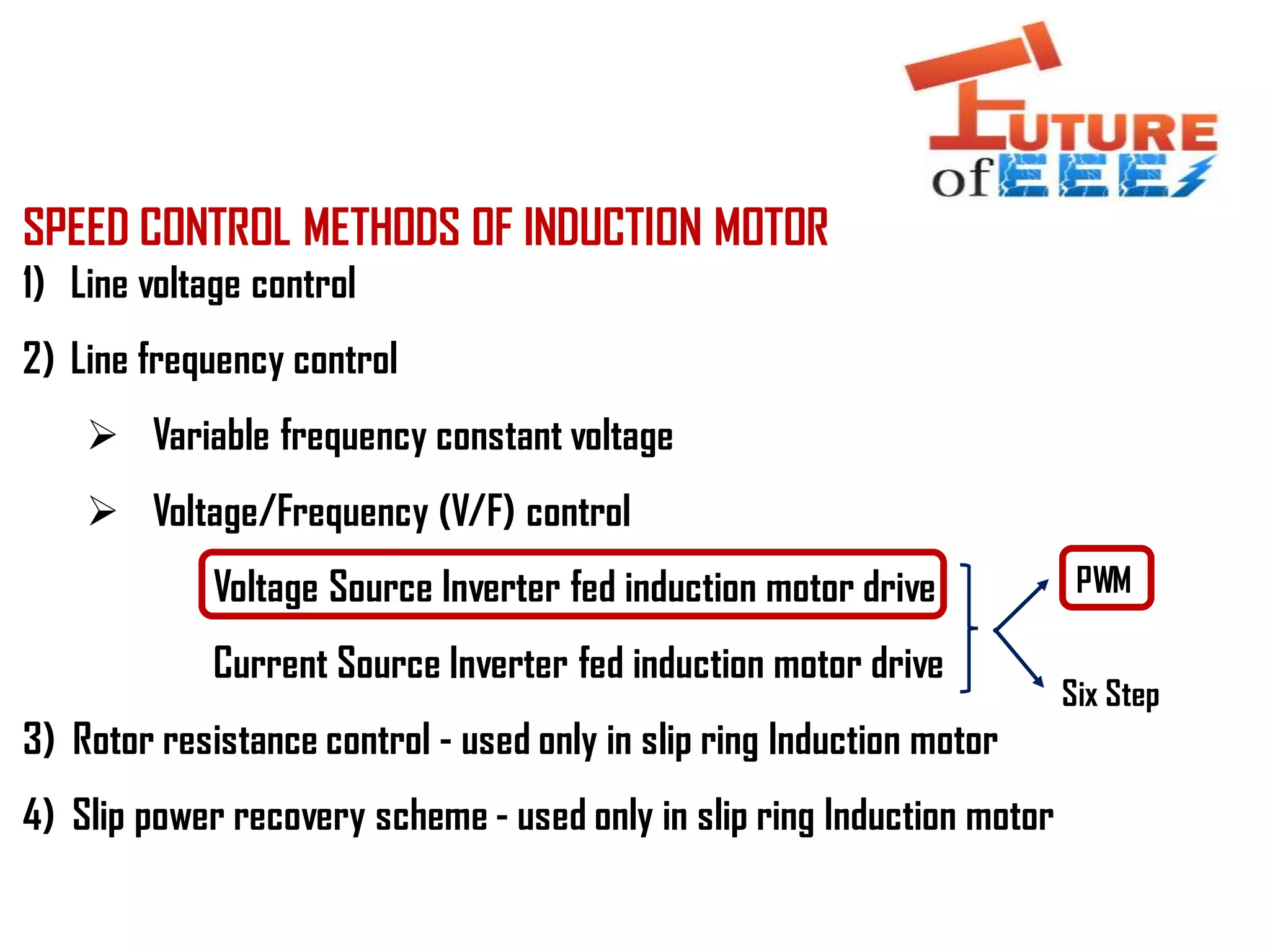
The document discusses various speed control methods for induction motors, including line voltage control, line frequency control, rotor resistance control, and slip power recovery schemes. It details the operation of PWM systems using voltage source inverters and how to control voltage magnitude and frequency through modulation techniques. Additionally, it explains the significance of gate voltages in PWM and the relationship between sinusoidal and triangular signals in controlling motor speeds.
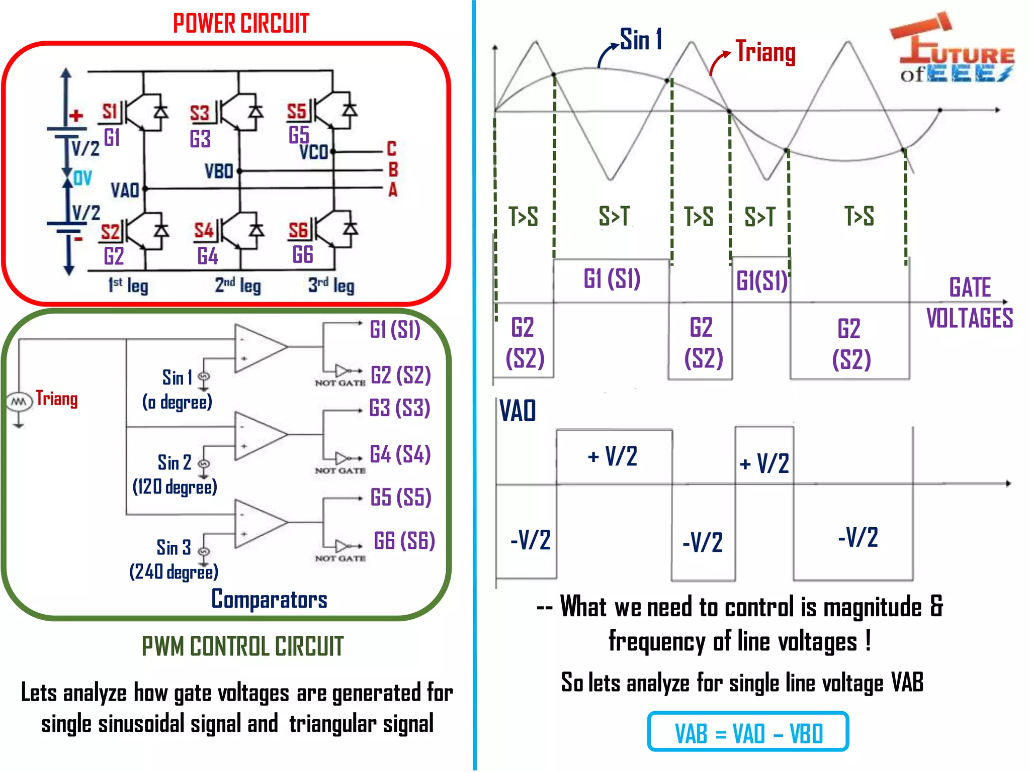
![HOW CONTROLLED GATE VOLTAGES ARE GENERATED IN PWM?
Sinusoidal /
Modulating
signal
Triangular/
Carrier
Signal
Comparators
G1 (S1)
[Upper]
G2 (S2)
[Lower]
G3 (S3)
[Upper]
G5 (S5)
[Upper]
G4 (S4)
[Lower]
G6 (S6)
[Lower]
So that both upper & lower transistor
will not turn ON @ the same time – So
Short circuit will not happen!
0 degree
120 degree
240 degree
1st leg
2nd leg
3rd leg](https://image.slidesharecdn.com/lec6-vsi-pwm-200927144443/75/Voltage-Source-Inverter-VSI-Pulse-Width-Modulation-PWM-3-2048.jpg)