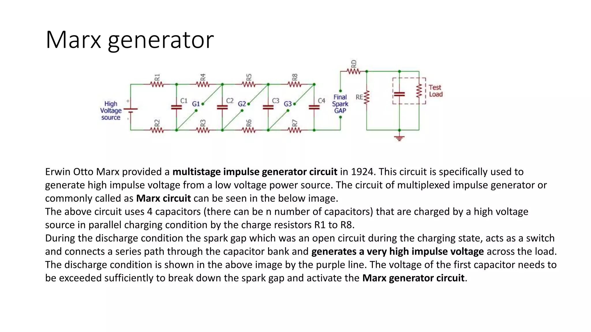
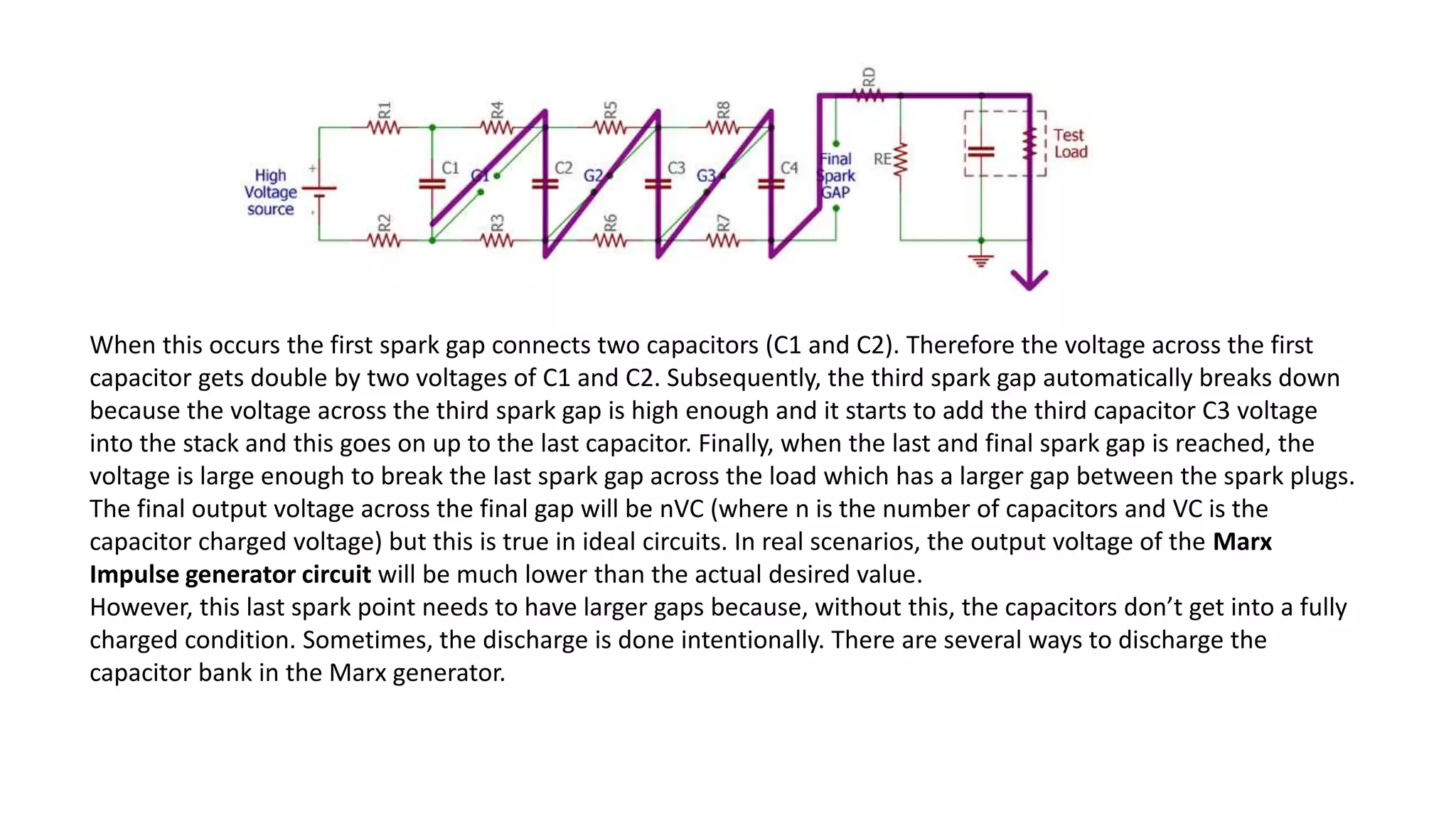
College Call Girls Nashik Nehal 7001305949 Independent Escort Service Nashik
MARX Generator.pptx
1.
2. Impulse Generator
surges are a very critical thing and it is a nightmare for every circuit
designer. These surges are commonly referred to as impulse which can
be defined as a high voltage, typically in a few kV which exists for a
short duration of time. The characteristics of an impulse voltage can be
noticed with a High or Low fall time followed by a very high rise time of
voltage, Lightning is an example of natural causes which causes Impulse
voltage. Since this Impulse voltage can severely damage electrical
equipment, it is important to test our devices to work against impulse
voltage. This is where we use an Impulse Voltage generator which
generates high voltage or current surges in a controlled testing set-up.
3. Impulse Voltage Waveform
The wave is getting to its maximum 100 percent peak within 2 uS. This is very fast, but the high
voltage is losing its strength with a span of 40uS almost. Therefore, the pulse has a very short
or fast rise time whereas a very slow or long fall time.
4. Single Stage Impulse Generator
• The above circuit consists of two capacitors and two resistances. The spark Gap (G) is an electrically isolated gap
between two electrodes where electrical sparks happen. A high voltage power source is also shown in the above
image. Any impulse generator circuit needs at least one large capacitor that is charged to an appropriate voltage
level and then discharged by a load. In the above circuit, the CS is the charging capacitor. This is a high voltage
capacitor typically more than a 2kV rating (depends on the desired output voltage). The capacitor CB is the load
capacitance that will discharge the charging capacitor. The resistor and RD and RE control the wave shape.
• If the above image observed carefully, we can find that the G or spark gap has no electrical connection. Then how
does the load capacitance get the high voltage? Here is the trick and by this one, the above circuit acts as an
impulse generator. The capacitor is charged until the capacitor’s charged voltage is enough to cross the spark gap.
An electrical impulse generated across the spark gap and high voltage gets transferred from the left electrode
terminal to the right electrode terminal of the spark gap and thus making it a connected circuit.
• The response time of the circuit can be controlled by varying the distance between two electrodes or changing the
capacitors fully charged voltage. The output impulse voltage calculation can be done by calculating the output
voltage waveform with
5. Disadvantages of Single Stage Impulse Generator
• The major disadvantage of a single-stage impulse generator circuit is
the physical size. Depending on the high voltage rating, the components
get bigger in size. Also, high impulse voltage generation requires a high DC
voltage. Therefore, for a single-stage impulse voltage generator circuit, it
gets quite difficult to get optimum efficiency even after using large DC
power supplies.
• The spheres that are used for the gap connection also required very high in
size. The corona that is gets discharged by the impulse voltage generation
is very difficult to suppress and reshape. The electrode life gets shorten and
requires replacement after a few cycles of repetition.
6. Marx generator
Erwin Otto Marx provided a multistage impulse generator circuit in 1924. This circuit is specifically used to
generate high impulse voltage from a low voltage power source. The circuit of multiplexed impulse generator or
commonly called as Marx circuit can be seen in the below image.
The above circuit uses 4 capacitors (there can be n number of capacitors) that are charged by a high voltage
source in parallel charging condition by the charge resistors R1 to R8.
During the discharge condition the spark gap which was an open circuit during the charging state, acts as a switch
and connects a series path through the capacitor bank and generates a very high impulse voltage across the load.
The discharge condition is shown in the above image by the purple line. The voltage of the first capacitor needs to
be exceeded sufficiently to break down the spark gap and activate the Marx generator circuit.
7. When this occurs the first spark gap connects two capacitors (C1 and C2). Therefore the voltage across the first
capacitor gets double by two voltages of C1 and C2. Subsequently, the third spark gap automatically breaks down
because the voltage across the third spark gap is high enough and it starts to add the third capacitor C3 voltage
into the stack and this goes on up to the last capacitor. Finally, when the last and final spark gap is reached, the
voltage is large enough to break the last spark gap across the load which has a larger gap between the spark plugs.
The final output voltage across the final gap will be nVC (where n is the number of capacitors and VC is the
capacitor charged voltage) but this is true in ideal circuits. In real scenarios, the output voltage of the Marx
Impulse generator circuit will be much lower than the actual desired value.
However, this last spark point needs to have larger gaps because, without this, the capacitors don’t get into a fully
charged condition. Sometimes, the discharge is done intentionally. There are several ways to discharge the
capacitor bank in the Marx generator.
8. • Components of a Multistage Impulse Generator Circuit:
A Multistage Impulse Generator Circuit requires several components parts for flexibility and for the production of the required waveshape. These may
be grouped as follows:
1.d.c. Charging Set: The charging unit should be capable of giving a variable d.c. voltage of either polarity to charge the generator capacitors to the
required value.
2.Charging Resistors: These will be non-inductive high value resistors of about 10 to 100 kilo-ohms. Each resistor will be designed to have a maximum
voltage between 50 and 100 kV.
3.Generator Capacitors and Spark Gaps: These are arranged vertically one over the other with all the spark gaps aligned. The capacitors are designed
for several charging and discharging operations. On dead short circuit, the capacitors will be capable of giving 10 kA of current. The spark gaps will be
usually spheres or hemispheres of 10 to 25 cm diameter. Sometimes spherical ended cylinders with a central support may also be used.
4.Wave-shaping Resistors and Capacitors: Resistors will be non-inductive wound type and should be capable of discharging impulse currents of 1000
A or Each resistor will be designed for a maximum voltage of 50 to 100 kV. The resistances are bifilar wound on non-inductive thin flat insulating
sheets. In some cases, they are wound on thin cylindrical formers and are completely enclosed. The load capacitor may be of compressed gas or oil
filled with a capacitance of 1 to 10 nF.
Modern impulse generators have their wave-shaping resistors included internally with a flexibility to add additional resistors outside, when the
generator capacitance is changed (with series parallel connection to get the desired energy rating at a given test voltage). Such generators optimize
the set of resistors. A commercial impulse voltage generator uses six sets of resistors ranging from 1.0 ohm to about 160 ohms with different
combinations (with a maximum of two resistors at a time) such that a resistance value varying from 0.7 ohm to 235 ohms per stage is obtained,
covering a very large range of energy and test voltages. The resistors used are usually resin cast with voltage and energy ratings of 200 to 250 kV and
2.0 to 5.0 kWsec. The entire range of lightning and switching impulse voltages can be covered using these resistors either in series or in parallel
combination.
5.Triggering System: This consists of trigger spark gaps to cause spark breakdown of the gaps.
6.Voltage Dividers: Voltage dividers of either damped capacitor or resistor type and an oscilloscope with recording arrangement are provided for
measurement of the voltages across the test object. Sometimes a sphere gap is also provided for calibration purposes.
7.Gas insulated impulse generators: Impulse generators rated for 4 MV or above will be very tall and require large space. As such they are usually
located in open space and are housed in an insulated enclosure. The height of a 4.8 MV unit may be around 30 m. To make the unit compact, a
compressed gas, such as N2 or SF6 may be used as the insulation.
9. • Capacitor discharging techniques in Marx Generator:
• Pulsing additional Trigger electrode: Pulsing an additional trigger
electrode is an effective way to intentionally trigger the Marx
generator during fully charge condition or in a special case. The
additional trigger electrode is called as Trigatron. There are different
shapes and sizes Trigatron available with different specifications.
• Ionizing the air in the gap: Ionized air is an effective path that is
beneficial to conduct the spark gap. The ionization is done by using a
pulsed laser.
• Reducing the air pressure inside the gap: The reduction of air
pressure is also effective if the spark gap is designed inside a chamber.
10. Disadvantages of the Marx Generator
• Long charge time: Marx generator uses resistors to charge the capacitor.
Thus the charge time gets higher. The capacitor that is closer to the power
supply gets charged faster than the others. This is due to the increased
distance because of increased resistance between the capacitor and the
power supply. This is a major drawback of the Marx generator unit.
• Loss of efficiency: Due to the same reason as previously described, as the
current flows through the resistors, the efficiency of the Marx generator
circuit is low.
• The short life span of the spark gap: The repetitive cycle of discharge
through the spark gap shortens the lifetime of the electrodes of a spark gap
that needs to be replaced from time to time.
• The repetition time of charge and discharge cycle: Due to the high charge
time, the repetition time of the impulse generator is very slow. This is
another major drawback of the Marx generator circuit.
11. Application of Impulse Generator Circuit
• The major application of the impulse generator circuit is to test high
voltage devices. Lightning arresters, Fuses, TVS diodes, different
types of surge protectors, etc are tested using the Impulse voltage
generator. Not only in the testing field, but the Impulse generator
circuit is also an essential instrument that is used in nuclear physics
experiments as well as in lasers, fusion and plasma device industries.
• The Marx generator is used for the simulation purposes of lightning
effects on power-line gear and in aviation industries. It is also used in
X-Ray and Z machines. Other uses, such as insulation testing of
electronic devices are also tested using impulse generator circuits.