The document discusses AC motor drives and induction motor drives. It provides details on:
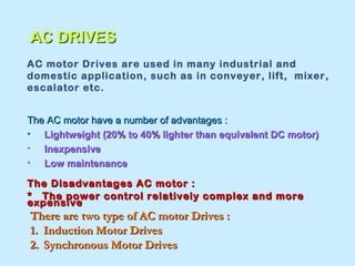
1. AC motor drives are commonly used in industrial and domestic applications due to their light weight, low cost, and low maintenance requirements. Their power control is relatively complex.
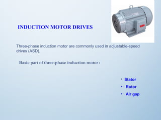
2. There are two main types of AC motor drives - induction motor drives and synchronous motor drives. Induction motors are commonly used in adjustable speed drives.
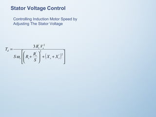
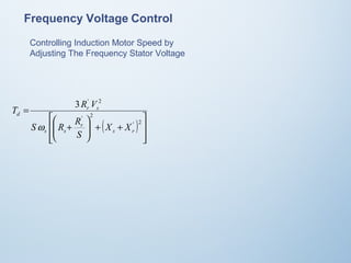
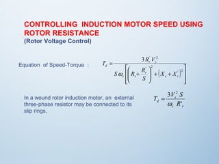
3. Speed control of induction motors can be achieved by varying the stator voltage and frequency. Rotor resistance control using an external resistor is also described for wound rotor induction motors.


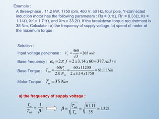
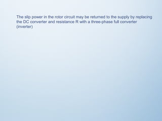
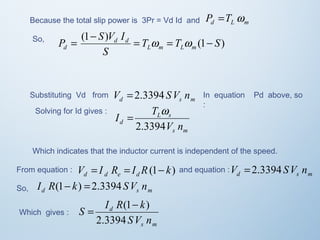
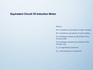
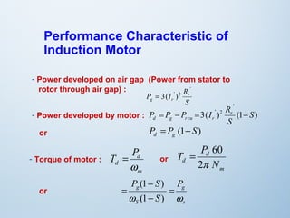
![The stator winding are supplied with balanced three-phase AC voltage,
which produce induced voltage in the rotor windings. It is possible to
arrange the distribution of stator winding so that there is an effect of
multiple poles, producing several cycle of magnetomotive force (mmf) or
field around the air gap.
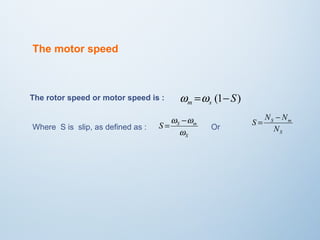
The speed of rotation of field is called the synchronous speed ws , which
is defined by :
ωs is syncronous speed [rad/sec]
Ns is syncronous speed [rpm]
p is numbers of poles
ω is the supply frequency [rad/sec]
f is the supply frequency [Hz]
Nm p is motor speed
w = 2w
s p
N =120
f s
or](https://image.slidesharecdn.com/acdrives-140826081923-phpapp01/85/A-C-Drives-4-320.jpg)
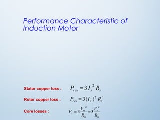
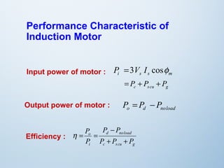
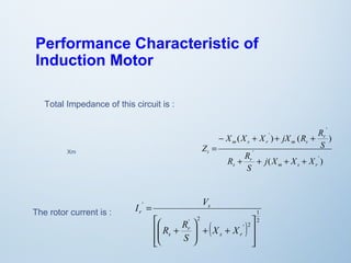

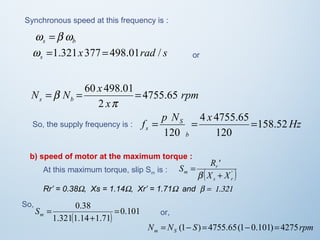
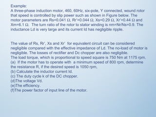
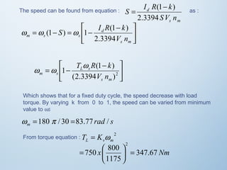
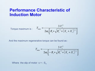
![Performance Characteristic of
Induction Motor
Starting speed of motor is wm = 0 or S = 1,
Starting torque of motor is :
3 ' 2
( )
ù
ú ú
û
T R V
é
æ
ê ê
ë
ö
+ + ÷ ÷ø
ç çè
R +
R
=
' 2
' 2
s r
r
s s
r s
st
X X
S
w
d Td
Slip for the maximum torque Smax can be found by setting : = 0
dS
So, the slip on maximum torque is :
'
S R
r
[( ) 2 ( ' ) 1
2
]2
max
R + X +
X
s s r
= ±](https://image.slidesharecdn.com/acdrives-140826081923-phpapp01/85/A-C-Drives-15-320.jpg)
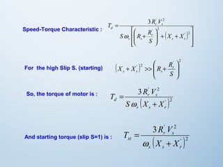
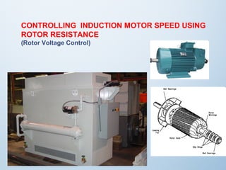
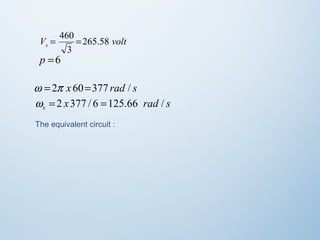
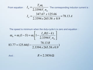
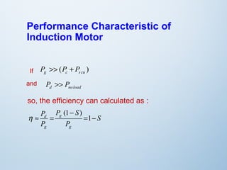
![For low slip S region, the motor speed near unity or synchronous
speed, in this region the impedance motor is :
X + X ' 2 << R' >>
( ) r
R
s r s
S
3 2
w
T V S
s
d R
'
s r
=
So, the motor torque is :
'
S R
r
[( ) 2 ( ' ) 1
2
]2
max
R + X +
X
s s r
And the slip at maximum torque is : = ±
The maximum motor torque is :
( )
ù
ú úû
T R V
é
æ
S R R
ê êë
3 ' 2
ö
+ + ÷ ÷ø
ç çè
+
=
' 2
' 2
s r
r
s s
r s
d
X X
S
w](https://image.slidesharecdn.com/acdrives-140826081923-phpapp01/85/A-C-Drives-18-320.jpg)