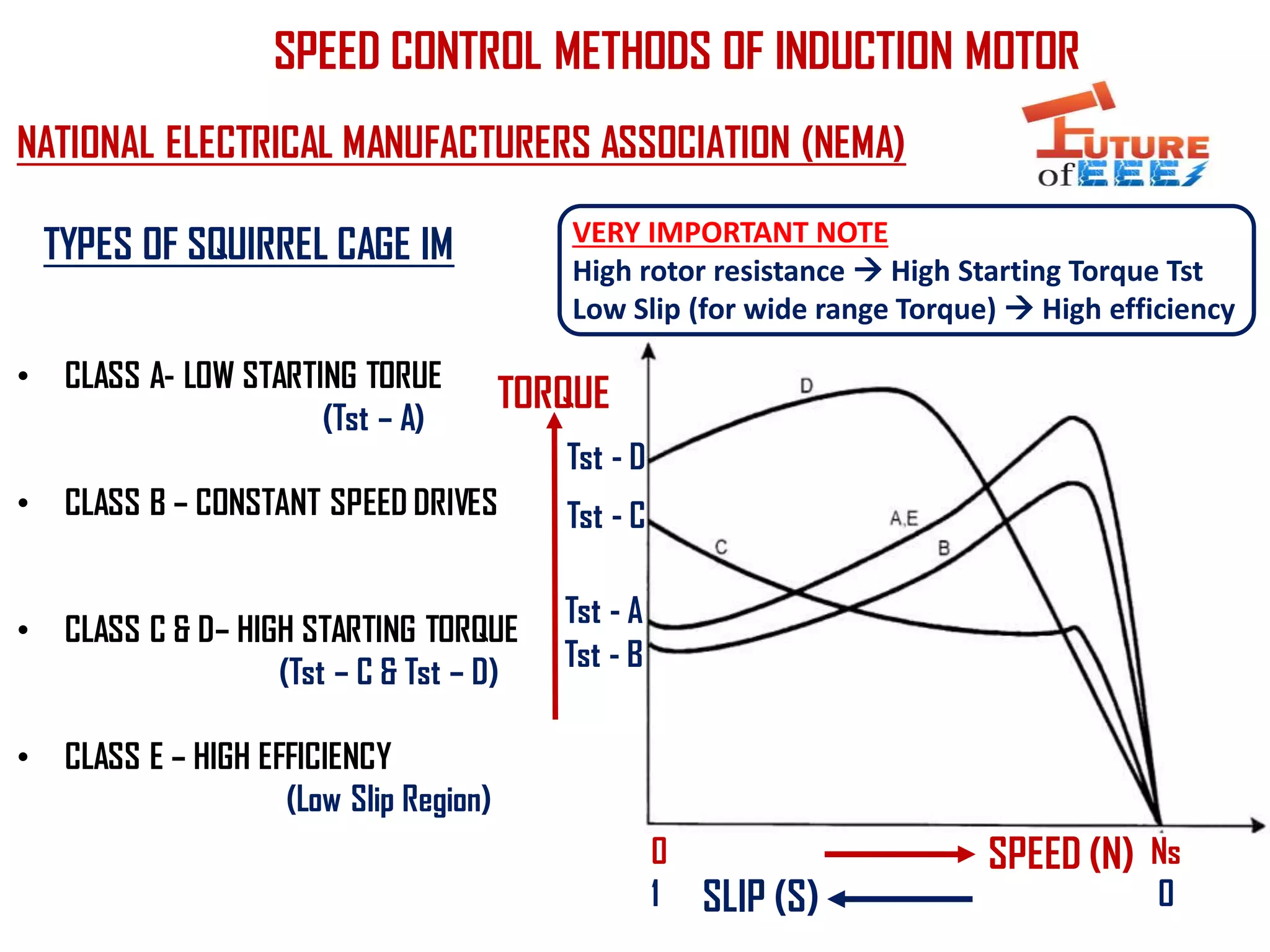
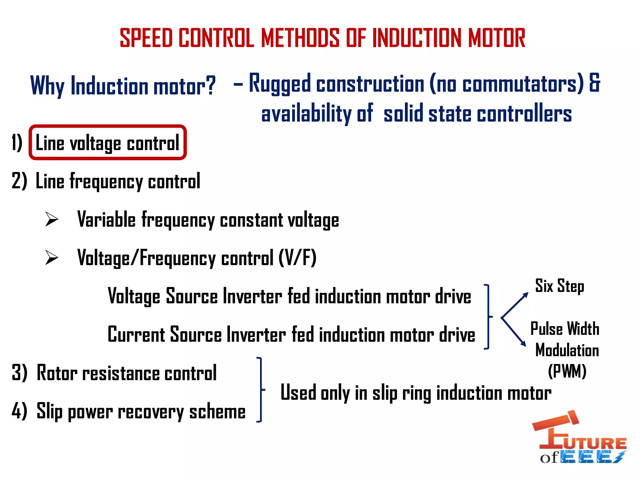
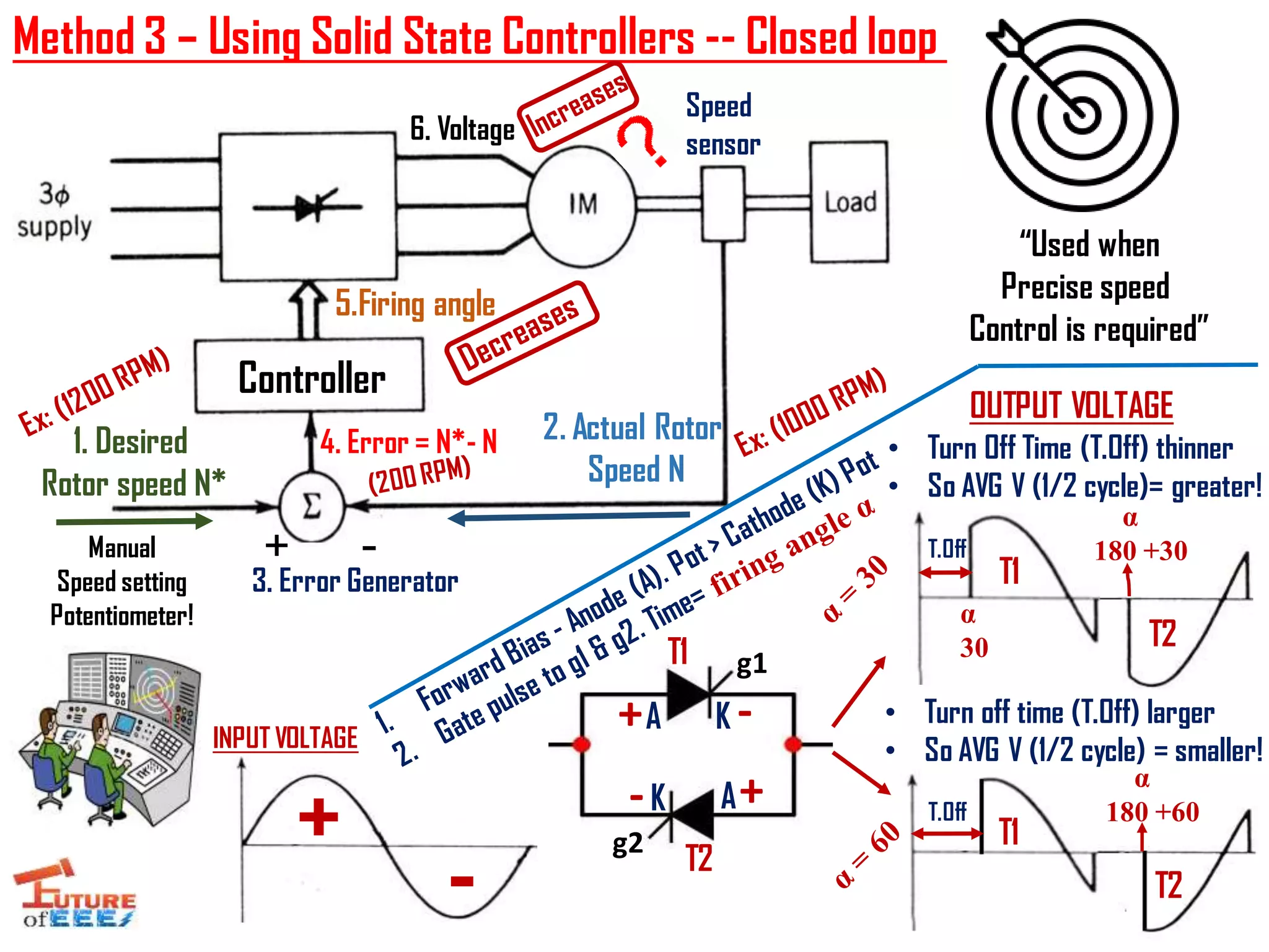
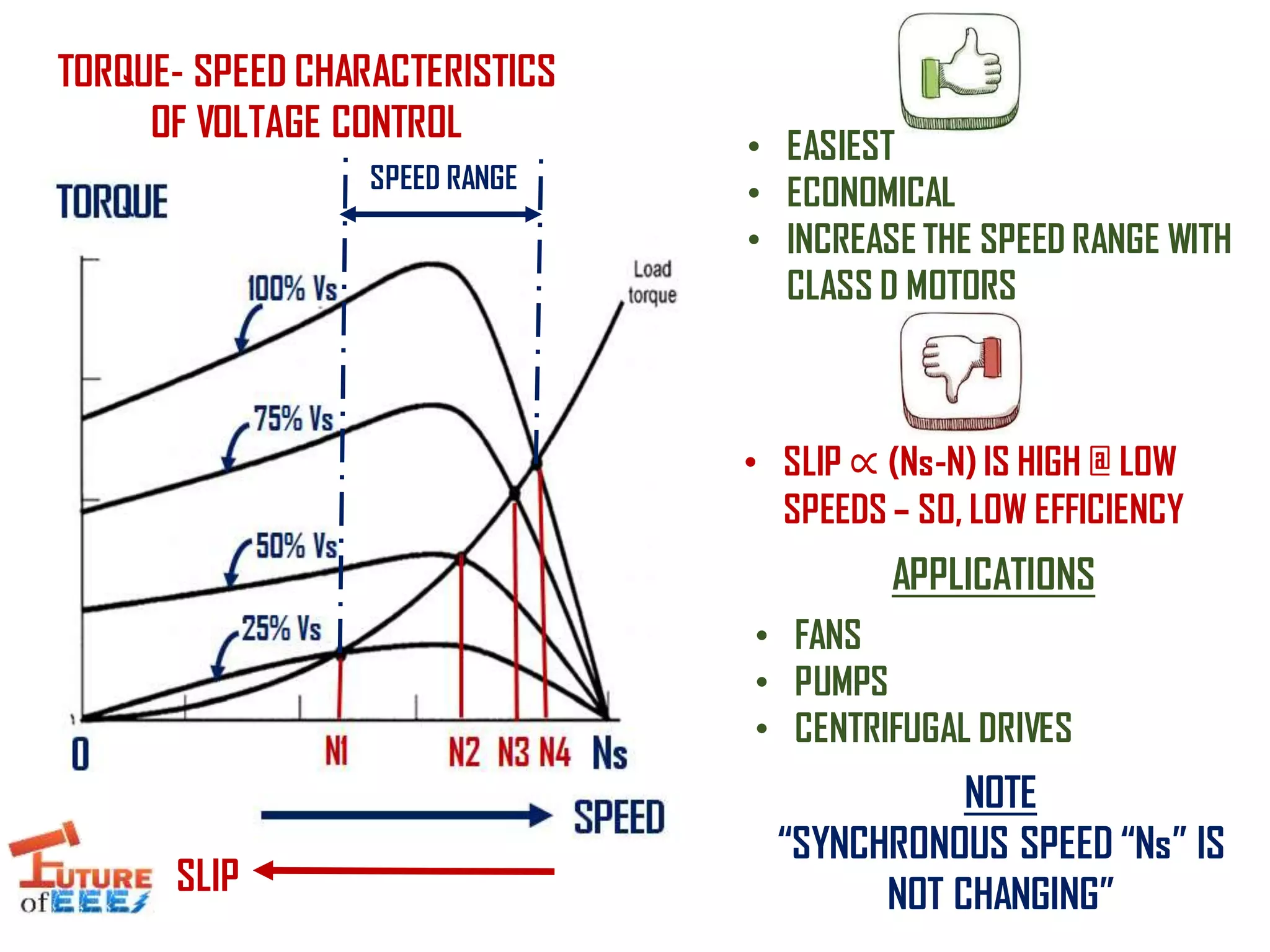
This presentation describes the
Line Voltage Control - Torque Speed Characteristics - Methods -Advantages - Disadvantages - Applications of Voltage control
V/F control of Induction Motor - Variable voltage and Variable frequencyCitharthan Durairaj
This presentation describes Principle of Variable voltage and Variable frequency- the open loop & closed loop Voltage/Frequency (V/F) control of Induction motor with torque speed characteristics -
This presentation describes the Voltage Source Inverter (VSI) - Six Step Switching - Pole voltages and its control - Frequency control of line voltages
The document describes the design and performance of a low-cost function generator capable of producing square, triangular, and sine waveforms. The key objectives were to generate these waveforms with amplitude control from 4 Hz to over 1 MHz for under $50. The design uses a voltage controlled oscillator, level detector, sine shaping circuit, and variable power amplifier. Test results found it could produce the targeted waveforms from 4 Hz to 500 kHz with less than 1.2% total harmonic distortion.
The document discusses different types of starters used for induction motors, including direct online, star-delta, and autotransformer starters. It explains that starters are needed to limit high starting currents in induction motors, which could damage motor windings. The star-delta starter is described in more detail, noting that it initially connects the stator in a wye configuration to reduce starting current and torque by a factor of sqrt(3) compared to direct online starting, allowing the motor to safely accelerate before switching to a delta connection for full voltage operation.
This document provides information about the RCP2-GRLS ROBO Cylinder 2-Finger Gripper Mini Lever Type 42mm Width Pulse Motor actuator. It includes specifications such as a gripping force range of 6.4N, a stroke of 180 degrees, and compatibility with controllers like the PMEC-C-20PI-NP-2-1. Dimensions and installation details are also listed. The actuator can be purchased from Electromate.
THREE PHASE INDUCTION MOTOR, Rotating Magnetic Field (RMF), Slip, Constructio...Waqas Afzal
THREE PHASE INDUCTION MOTOR
Advantages/D-Advantages/Applications
Rotating Magnetic Field (RMF)
Slip and slip frequency
Construction
Principal of Operation
Torque-speed characteristics
Speed control
Power flow
Equivalent Circuit
Maximum torque
Specifications
The document provides information on the LM555 timer integrated circuit. It can be used to generate precise time delays or oscillations. In monostable mode, the time is controlled by a single external resistor and capacitor. In astable mode, frequency and duty cycle are set by two resistors and a capacitor. It has applications in timing, pulse generation, and more. Key specifications include timing accuracy better than 0.5% and an output that can source or sink up to 200mA.
Vibration analysis uses FFT to transform time domain vibration data into the frequency domain spectrum. Key parameters like acceleration, velocity, crest factor, kurtosis, and noise levels are used to monitor rotational forces, impacts/shocks, and friction within machines. Fault frequencies corresponding to machine components like bearings and gears are identified and compared to spectral peaks to diagnose issues. Phase analysis can also identify unbalance or misalignment. Proper data collection and machine parameters like RPM are critical for effective vibration analysis.
Study of vco_Voltage controlled OscillatorNeha Mannewar
Voltage controlled Oscillator,Voltage controlled oscillator is a type of oscillator where the frequency of the output oscillations can be varied by varying the amplitude of an input voltage signal.Voltage controlled oscillators are commonly used in frequency (FM), pulse (PM) modulators and phase locked loops (PLL). Another application of the voltage controlled oscillator is the variable frequency signal generator itself.
Digital timer switches are utilized to control the task of electrical gadgets dependent on a customized timetable. This undertaking portrays a programmable digital timer dependent on the PIC16F628A microcontroller that can be customized to plan the on and off activity of an electrical apparatus. The apparatus is controlled through a hand-off switch. This clock change enables you to set both on and off time. That implies, you can program when would you like to turn the gadget on and for to what extent you need it to be stayed on. The greatest time interim that you can set for on and off activity is 99 hours and 59 minutes. The task gives an intuitive UI utilizing a 16×2 character LCD alongside 4 push catches.
This document provides specifications for the RCP2-GR3LS ROBO Cylinder 3-Finger Gripper Lever Type including:
1. Key specifications like a stroke of 19 degrees, maximum gripping force of 200N, and compatible controllers.
2. A graph showing how gripping force varies with current limit from 0-70%.
3. Dimensions and mounting information for the actuator.
4. An overview of compatible simple and programmable motion controllers for the RCP2 series actuators.
This document summarizes the NE555, SA555, and SE555 monolithic timing circuits. It provides:
1) Pin connections, electrical characteristics including timing accuracy, input/output voltage levels, and operating conditions.
2) Descriptions and schematics for operating the NE555 in monostable (one-shot) and astable (oscillator) modes using external resistors and capacitors to control timing.
3) Examples of applications including pulse width modulation, linear ramp generation, and a 50% duty cycle oscillator. Tables, figures and waveforms illustrate the timer's operation and specifications.
The document provides information on the LM Series direct coupled actuators from Belimo, including the LM24-3 US and LM24-SR-2.0 US models. It describes the actuators as being small yet powerful, with a minimum 35 in-lb torque allowing control of damper areas up to 8 square feet. The LM24-3 US is for on-off/floating point control using 24V power, while the LM24-SR-2.0 US provides proportional control via a 2-10VDC or 4-20mA input signal and includes electronic angle limiting from 20-100% rotation. Installation and operation instructions are included along with specifications, dimensions, accessories and agency listings for the actu
Icel os 21-mesco_ao-1221_minipa_mo-1225_yb4328_2x5mv,20mhz_portable_oscillosc...vobetinha
This document provides specifications and operating instructions for two oscilloscope models: a 20MHz model and a 15MHz model. It includes details on their vertical deflection systems, triggering systems, horizontal sweep systems, X-Y mode functions, and CRT specifications. The document also provides diagrams of the front and rear panels showing the various control buttons and terminals. It describes the functions of each control button for settings like deflection factor, coupling mode, sweep rate, trigger level, and more.
This document provides information about the RCP2 ROBO Cylinder, including:
1) It uses a pulse motor so load capacity decreases at higher speeds, and it includes a graph showing speed vs load capacity.
2) It is available in different stroke lengths from 25mm to 100mm in 25mm increments, and can be ordered with standard or custom cable lengths.
3) It provides specifications like a ball screw drive, rod diameter, operating temperature range, and maximum load capacities for different lead sizes.
1) The document provides specifications for the RCP2W-GRLS ROBO Cylinder, a 2-finger gripper mini lever type cylinder with a 42mm width and pulse motor.
2) It can be operated with compatible controllers including the PMEC-C-20PI-NP-2-1, PSEP-C-20PI-NP-2-0, and PCON-C-20PI-NP-2-0, and has a maximum grip force of 7N, stroke of 180 degrees, and deceleration ratio of 30.
3) Dimensions and installation details are provided along with compatible robot cable options.
The document provides specifications for the RCP2-GR3LM ROBO Cylinder 3-Finger Gripper Lever Type 80mm Width Pulse Motor. It includes details on its maximum gripping force, stroke, speed, compatible controllers, cable options, and specifications for the actuator such as positioning repeatability and operating temperature range. Compatible controllers include the PMEC, PSEP, PCON, RPCON, and PSEL which support different input types and programmability levels.
Vibration analysis is used to identify issues in rotating machinery by analyzing vibration signatures. Common issues that can be identified include unbalance, misalignment, looseness, bearing faults, and resonance. Vibration signals are analyzed in the time, frequency, and phase domains to identify characteristic frequencies, amplitudes, and phase relationships that correspond to different problem sources. Overall vibration levels and narrowband spectrum peaks are monitored over time for trends that may indicate developing issues.
This document discusses vibration analysis at thermal power plants. It outlines the objectives of vibration monitoring, which include improving equipment protection, safety, maintenance procedures, and extending equipment life. Vibration monitoring measures characteristics like amplitude and frequency to identify abnormal conditions. Common defects that can be detected through vibration analysis are unbalance, misalignment, loose components, rotor rub, bearing issues, and blade/vane pass frequencies. Online monitoring systems are used at thermal plants to continuously monitor critical equipment like turbines, generators, and pumps to detect faults early and avoid failures. Standards provide guidelines for effective vibration analysis and maintenance.
The document is a project report on using an astable multivibrator with a 555 timer integrated circuit to generate a square wave oscillator. It includes an introduction to the 555 timer, its pinout, block diagram and applications. The circuit diagram shows a 555 timer connected with resistors and a diode to produce a 50% duty cycle square wave. The report will analyze the circuit operation and timing waveforms. It includes the 555 timer datasheet and concludes that a square wave can be generated in astable mode using the 555 timer and diode.
ELECTRICAL AND INSTRUMENTATION ENGINEERING COURSE
Lect 2- Electric Machines
Please subscribe to my YouTube Channel for best training lectures:
https://www.youtube.com/channel/UCRkUJFOsyZG1E1LDWzUr_hw
This document provides information on the RCP2CR-GRLS Cleanroom ROBO Cylinder 2-Finger Gripper Mini Lever Type 42mm Width, including its specifications, compatible controllers, cable options, and dimensions. It can adjust its gripping force from 20-70% of current limits. It has a stroke of 30 degrees and maximum gripping force of 6.4N. Compatible controllers include the PMEC-C-20PI-NP-2-1 easy to use solenoid valve type and PCON-C-20PI-NP-2-0 positioning type.
This technical memo discusses changes needed to an electronic circuit diagram. The memo notes that the value of resistor R246, which is connected to the input of chip U38, is too large and should be changed to a value less than 2.2k. It also states that the inverting symbol on chip U100 should be changed to a non-inverting symbol in order for the circuit to switch in normal conditions as the output is currently 1 but needs to be 0. Simulation waveforms are included showing the voltage levels over time at nodes U101:1 and R139:1.
This document summarizes a research paper on implementing smooth transitions between optimal control modes in a switched reluctance motor (SRM). It begins with introductions to SRM technology and an overview of the paper contents. It then covers the operating principles, characteristics, control strategies, and modes of operation of SRMs. The document describes the development of a Simulink model for a proposed optimal controller, including subsystems for pulse width modulation and single pulse control. Simulation results are presented and analyzed for no-load operation, with load, and under speed and torque dynamics. The analysis shows the controller varies turn-on and turn-off angles optimally under different operating conditions to reduce ripple and enable smooth transitions between control modes. The conclusion
The document provides specifications for Pacific Scientific T-Series NEMA 23 high torque motors, including torque ratings, phase configurations, connection options, and performance characteristics. It lists motor models, their holding torques in oz-in and N-m, phase currents, resistance, inductance, detent torque, thermal resistance, and inertia. Graphs show torque-speed curves for various motor models operated at different current levels.
The document provides specifications for the RCP2-RTCB/RTCBL ROBO Cylinder rotary actuator. It includes details on:
1) The output torque and allowable moment of inertia decrease as rotational speed increases, with graphs showing speed and load capacity limits.
2) The rated acceleration is 0.3G while moving.
3) It can be used with various compatible controllers, including position, pulse train input, and program control types.
The document provides specifications for the AZBE25A20 analog servo drive. The drive is designed to drive brushless and brushed DC motors at high switching frequencies up to 25A continuous current. It has features like four quadrant regenerative operation, direct board integration, encoder and tachometer feedback support, and hardware protections. The drive requires only a single DC power supply and complies with safety and emissions standards.
The AZBE10A20 is an analog servo drive designed to drive brushless and brushed DC motors. It can provide up to 10A of continuous current and operates on an input voltage range of 40-175VDC. The drive has features such as four quadrant regenerative operation, direct board integration, encoder and tachometer feedback support, and hardware protections against overvoltage, overcurrent, and more.
The AZBE40A8 is a PWM servo drive designed to drive brushless and brushed DC motors. It can provide a peak current of 40A and continuous current of 20A, with a supply voltage range of 10-80VDC. The drive is fully protected against over-voltage, under-voltage, over-current and other faults. It supports various feedback and operation modes including encoder velocity control.
The document describes an analog servo drive called the AZBE60A8. It is designed to drive brushless and brushed DC motors at high switching frequencies. Key specifications include a peak current of 60A, continuous current of 30A, and operating voltage range of 10-80VDC. It has protection against overvoltage, undervoltage, overcurrent and more. It can utilize encoder, hall sensor, or tachometer feedback and supports various motor and operation modes.
SEMINAR TOPIC- 3 PHASE SELETOR AND PREVENTER FOR INDUSTRIAL APPS. 2007.pptSUJAY RAVI KALE
This document describes a three phase selector and preventer for industrial appliances. It discusses the need for such a device to drive three phase loads from single phase power and protect appliances from phase failures. The project aims to generate three phase power from single phase using a microcontroller and generate PWM output to allow frequency control from 10-100Hz for speed control of induction motors. Main components include a regulated power supply, DIP switches, microcontroller, opto-isolators, signal amplifiers, inverter circuitry, and gate drive power supply.
This document provides specifications for various linear servo motors in the RCL series. It includes details for several slider type motors with mini or standard sizes and strokes ranging from 20mm to 58mm. For each motor, information is given on the configuration, load capacity, stroke, speed, dimensions, weight and compatible controllers. The document also lists controller models for operating the linear servo motors, including positioner, pulse train input and program control types.
The RCP2 ROBO Cylinder is a rotary actuator with the following key specifications:
1) It has a maximum torque that decreases with increasing rotational speed.
2) It has an allowable moment of inertia for the rotated workpiece that varies with rotational speed.
3) Its rated acceleration is 0.3G while moving.
(1) The RCP2 ROBO Cylinder rotary actuator uses a pulse motor with varying output torque and allowable moment of inertia based on rotational speed.
(2) It can rotate 330 or 360 degrees depending on the model, with a maximum rated acceleration of 0.3G.
(3) The document provides specifications, diagrams, compatible controller options and other details about the actuator.
This document discusses the design of a closed-loop speed controller for a single-phase AC induction motor using pulse-width modulation (PWM) of the TRIAC firing angle. It describes how varying the TRIAC firing delay can control motor speed, and how adding a tacho generator and error amplifier in a closed control loop enables set-point speed regulation. Key components include the zero-crossing detector, PWM generator, TRIAC driver, power supply, and control loop circuitry around the motor and tacho generator.
The document provides specifications for the AZBH25A20 analog servo drive. The drive is designed to drive brushless and brushed DC motors at high switching frequencies. It has a peak current of 25A, continuous current of 12.5A, and operates on a DC supply voltage of 40-175VDC. The drive provides various protection features and supports different feedback and operation modes.
This document discusses micro stepping mode for stepper motors. It begins with an introduction to stepper motors and their basic operation. It then discusses different types of stepper motors and their characteristics. Micro stepping mode is described as a technique that provides additional intermediate positions between poles by proportioning current in the motor windings, allowing for smooth rotation over a wide speed range with high positional resolution. The document outlines the mathematics and electronics behind micro stepping control and provides experimental results demonstrating reduced resonance and noise with precise position control.
The document describes the SR30A series of brushless servo amplifiers manufactured by Electromate. The amplifiers can drive brushless motors with 3 phase sine wave current and have features like surface mount technology, small size, optical isolation, and DIP switch selectable modes. They provide functions such as four quadrant regenerative operation, resolver interface for sinusoidal commutation, and emulated encoder output. The amplifiers are fully protected and come in models SR10A40 and SR30A40 that can deliver peak currents of 10A and 30A respectively.
The SR30A Series are brushless servo amplifiers that can drive 3-phase brushless motors. They have features like surface mount technology, small size, optical isolation, DIP switch selectable modes, regenerative operation, and encoder emulation output. The amplifiers come in models SR10A40 and SR30A40 that can provide peak currents of 10A and 30A respectively. They require a single DC power supply and have protection against overvoltage, undervoltage, overcurrent and short circuits.
Applying Stepper Motors: Application Questions You Must Answer & Things to Wa...Design World
This webinar reviews some of the basic parameters necessary to properly select and apply stepper motor technology to motion applications. Topics included in this discussion review basic stepper speed-torque behavior including the stepper over-voltage ratio, a stepper in constant current operation vs. a stepper in voltage drive region, thermal ratings, the impact of winding changes on dynamic behavior, calculations and considerations for intermittent duty operation, motor/system accuracy, failure modes, and the application of all these criteria when applying stepper-based linear actuator products.
Engineers currently using stepper technology in their motion applications that want to understand how to apply stepper motor technology will benefit from this webinar.
In this webinar you will learn:
-Basic parameters necessary to properly select and apply stepper motor technology
-How to understand the stepper motor speed-torque curve and how to apply this to the application
-The main factors to consider when trying to optimize a stepper motor in a variety of applications
The document describes an analog servo drive called the BE25A20FAC. It has the following key specifications:
- It can deliver up to 25A of peak current and 12.5A of continuous current from a 30-130V AC power supply.
- It is designed to drive brushless DC motors and features four quadrant regenerative operation, adjustable current limits, and selectable operating modes including current, open loop, and encoder velocity modes.
- It provides motor commutation from hall sensors or an encoder, and supports feedback from halls, encoders, or a tachometer.
- It has adjustable parameters like loop gain, current limit, input gain and offset via onboard potentiometers.
The SR60A Series document describes brushless servo amplifiers that can drive 3-phase brushless motors. Key features include small size, surface mount technology, optical isolation, DIP switch selectable modes, regenerative operation, and fault protection. The amplifiers interface with motion controllers or can operate standalone, and require only a single DC power supply. Connector pinouts, switch functions, and operating modes are defined to help with setup and configuration.
Similar to Voltage control of Induction Motor (20)
Equivalent Circuit, Phasor Diagram, Power Factor Control , V & Inverted V Cur...Citharthan Durairaj
This video describes the Equivalent Circuit, Phasor Diagram, Power Factor Control , V & Inverted V Curve of Synchronous Motor
For video please click the below link
https://www.youtube.com/watch?v=GdEAc_IHLbA&t=118s
Closed Loop I-F control using six step current source inverterCitharthan Durairaj
This document describes the Closed loop I-F control of Induction motor using six step Current Source Inverter (CSI).
For Explanation video- Please see my you tube channel - Future of EEE
This presentation describes the per-phase equivalent circuit of induction motor - Power flow diagram - Ratio of air gap power, rotor copper loss and mechanical power developed.
Torque speed characteristics of Squirrel cage & Slip ring induction motorsCitharthan Durairaj
This video describes the Torque - Slip / Torque- Speed Characteristics of three phase squirrel cage induction motor and slip ring induction motor- also describes the Condition for the maximum torque - Pullout torque and Pullout torque equation
This presentation describes the Principle of Operation - Squirrel cage Induction motor
Classification of Induction motors
Rotating Magnetic flux- Relative Motion - Faradays law- Lenz law
This video describes the monitoring of sensor values/ random values using blynk app and FRED IoT
Steps to be done in Blynk App & Steps to be done in FRED IoT
This Presentation describes the
Introduction to IoT - What is IoT ?
An Example - Home automation - Hardware and Software
If you have questions, please don't hesitate to ask in the comment section.
Pls like, share and subscribe. Thank you!
#FutureofEEE
There are three main types of stepper motors: variable reluctance, permanent magnet, and hybrid. Variable reluctance stepper motors use changes in magnetic reluctance to rotate and can be single or multi-stack. They provide high torque but have torque ripple issues. Permanent magnet stepper motors use permanent magnets on the rotor and have bipolar drive circuits. They can achieve a 45 degree step angle through alternate single and two phase excitation. Hybrid stepper motors combine features of variable reluctance and permanent magnet motors, with a 4 pole stator and 5 pole rotor construction. Each motor type has advantages and disadvantages related to torque, torque ripple, and drive circuit complexity.
1) The document discusses permanent magnet brushless DC (PMBLDC) motors and their control. It explains that the desired current waveform for each phase must be estimated based on the instantaneous rotor position to satisfy the maximum torque at minimum current principle.
2) The desired current is provided to the phases through driver circuits containing six transistors, which are switched on based on whether the desired current is positive or negative.
3) Rotor position is typically sensed using three Hall sensors spaced 120 degrees apart, though sensorless control is also possible using back EMF measurements. Control circuit design and operation are also briefly outlined.
1) For alternators to operate in parallel, they must be synchronized by having equal line voltage, frequency, phase sequence, phase angle, and waveform.
2) When alternators are synchronized and operating in parallel with no load, a circulating current will flow if their speeds or excitations differ slightly.
3) This circulating current acts to resynchronize the alternators by speeding up the slower one and slowing the faster one through their functioning as motor and generator respectively, until steady state is reached with no circulating current.
Low power architecture of logic gates using adiabatic techniquesnooriasukmaningtyas
The growing significance of portable systems to limit power consumption in ultra-large-scale-integration chips of very high density, has recently led to rapid and inventive progresses in low-power design. The most effective technique is adiabatic logic circuit design in energy-efficient hardware. This paper presents two adiabatic approaches for the design of low power circuits, modified positive feedback adiabatic logic (modified PFAL) and the other is direct current diode based positive feedback adiabatic logic (DC-DB PFAL). Logic gates are the preliminary components in any digital circuit design. By improving the performance of basic gates, one can improvise the whole system performance. In this paper proposed circuit design of the low power architecture of OR/NOR, AND/NAND, and XOR/XNOR gates are presented using the said approaches and their results are analyzed for powerdissipation, delay, power-delay-product and rise time and compared with the other adiabatic techniques along with the conventional complementary metal oxide semiconductor (CMOS) designs reported in the literature. It has been found that the designs with DC-DB PFAL technique outperform with the percentage improvement of 65% for NOR gate and 7% for NAND gate and 34% for XNOR gate over the modified PFAL techniques at 10 MHz respectively.
6th International Conference on Machine Learning & Applications (CMLA 2024)ClaraZara1
6th International Conference on Machine Learning & Applications (CMLA 2024) will provide an excellent international forum for sharing knowledge and results in theory, methodology and applications of on Machine Learning & Applications.
HEAP SORT ILLUSTRATED WITH HEAPIFY, BUILD HEAP FOR DYNAMIC ARRAYS.
Heap sort is a comparison-based sorting technique based on Binary Heap data structure. It is similar to the selection sort where we first find the minimum element and place the minimum element at the beginning. Repeat the same process for the remaining elements.
CHINA’S GEO-ECONOMIC OUTREACH IN CENTRAL ASIAN COUNTRIES AND FUTURE PROSPECTjpsjournal1
The rivalry between prominent international actors for dominance over Central Asia's hydrocarbon
reserves and the ancient silk trade route, along with China's diplomatic endeavours in the area, has been
referred to as the "New Great Game." This research centres on the power struggle, considering
geopolitical, geostrategic, and geoeconomic variables. Topics including trade, political hegemony, oil
politics, and conventional and nontraditional security are all explored and explained by the researcher.
Using Mackinder's Heartland, Spykman Rimland, and Hegemonic Stability theories, examines China's role
in Central Asia. This study adheres to the empirical epistemological method and has taken care of
objectivity. This study analyze primary and secondary research documents critically to elaborate role of
china’s geo economic outreach in central Asian countries and its future prospect. China is thriving in trade,
pipeline politics, and winning states, according to this study, thanks to important instruments like the
Shanghai Cooperation Organisation and the Belt and Road Economic Initiative. According to this study,
China is seeing significant success in commerce, pipeline politics, and gaining influence on other
governments. This success may be attributed to the effective utilisation of key tools such as the Shanghai
Cooperation Organisation and the Belt and Road Economic Initiative.
KuberTENes Birthday Bash Guadalajara - K8sGPT first impressionsVictor Morales
K8sGPT is a tool that analyzes and diagnoses Kubernetes clusters. This presentation was used to share the requirements and dependencies to deploy K8sGPT in a local environment.
Understanding Inductive Bias in Machine LearningSUTEJAS
This presentation explores the concept of inductive bias in machine learning. It explains how algorithms come with built-in assumptions and preferences that guide the learning process. You'll learn about the different types of inductive bias and how they can impact the performance and generalizability of machine learning models.
The presentation also covers the positive and negative aspects of inductive bias, along with strategies for mitigating potential drawbacks. We'll explore examples of how bias manifests in algorithms like neural networks and decision trees.
By understanding inductive bias, you can gain valuable insights into how machine learning models work and make informed decisions when building and deploying them.
1. NATIONAL ELECTRICAL MANUFACTURERS ASSOCIATION (NEMA)
TYPES OF SQUIRREL CAGE IM
• CLASS A- LOW STARTING TORUE
(Tst – A)
• CLASS B – CONSTANT SPEED DRIVES
• CLASS C & D– HIGH STARTING TORQUE
(Tst – C & Tst – D)
• CLASS E – HIGH EFFICIENCY
(Low Slip Region)
Tst - A
Tst - B
Tst - C
Tst - D
SPEED (N)
TORQUE
SPEED CONTROL METHODS OF INDUCTION MOTOR
SLIP (S)
0
1
Ns
0
VERY IMPORTANT NOTE
High rotor resistance High Starting Torque Tst
Low Slip (for wide range Torque) High efficiency
2. SPEED CONTROL METHODS OF INDUCTION MOTOR
1) Line voltage control
2) Line frequency control
Variable frequency constant voltage
Voltage/Frequency control (V/F)
Voltage Source Inverter fed induction motor drive
Current Source Inverter fed induction motor drive
3) Rotor resistance control
4) Slip power recovery scheme
Why Induction motor?
Six Step
Pulse Width
Modulation
(PWM)
– Rugged construction (no commutators) &
availability of solid state controllers
Used only in slip ring induction motor
3. 1) LINE VOLTAGE CONTROL
INDUCTION
MOTOR
FAN LOAD
TORQUE
SPEED
Variable
Three
Phase
Stator
Voltage (Vs)
• EASIEST METHOD
• ECONOMICAL
TORQUE
SPEED
25% Vs
50% Vs
75% Vs
100% Vs
N1 N2 N3 N4
NEMA CLASS D CAN BE SUITABLE
TO GET WIDE SPEED RANGE
SPEED RANGE
Ns0
SPEED
TORQUE
4. TORQUE- SPEED CHARACTERISTICS
OF VOLTAGE CONTROL
How to change the “voltage”? (Implementation)
Method 1
Method 2
- Using “Auto transformer”
- Variation is smooth
- O/P -> Sinusoidal voltage
- Using “Solid State Controllers”
- O/P –> Non Sinusoidal !!
- Input Filter required – Large Applns
By changing the
“Firing angle - alpha”
5. 2. Actual Rotor
Speed N
4. Error = N*- N
5.Firing angle
6. Voltage
Method 3 – Using Solid State Controllers -- Closed loop
1. Desired
Rotor speed N*
-+3. Error Generator
“Used when
Precise speed
Control is required”
Manual
Speed setting
Potentiometer!
INPUT VOLTAGE
OUTPUT VOLTAGE
T1
T2
• Turn Off Time (T.Off) thinner
• So AVG V (1/2 cycle)= greater!
• Turn off time (T.Off) larger
• So AVG V (1/2 cycle) = smaller!
Controller
Speed
sensor
g1
g2
A K
AK
+
-
+ -
- +
T1
α
30
T.Off
T2
α
180 +30
T1
T2
T.Off
α
180 +60
6. TORQUE- SPEED CHARACTERISTICS
OF VOLTAGE CONTROL
• EASIEST
• ECONOMICAL
• INCREASE THE SPEED RANGE WITH
CLASS D MOTORS
• SLIP ∝ (Ns-N) IS HIGH @ LOW
SPEEDS – SO, LOW EFFICIENCY
NOTE
“SYNCHRONOUS SPEED “Ns” IS
NOT CHANGING”
• FANS
• PUMPS
• CENTRIFUGAL DRIVES
APPLICATIONS
SLIP
SPEED RANGE