Download to read offline

![29
References
[1] Daniel Hart, “AC Voltage Controllers,” in Power Electronics,
McGraw-Hill, 2011.
[2] B. L. Dokić and B. Blanuša, Power Electronics Converters and Regulators, 3rd ed.
Springer US, 2015.
[3] V.k.mehta and Rohit-mehta, “Silicon Controlled Rectifiers,” in principles of electronics,
1st ed., s.chand, 1980.
[4] M. H. Rahid, “AC-AC Converters,” in Power Electronics Handbook, Academic Press,
2001.](https://image.slidesharecdn.com/ac-acconveter-191104035138/85/Ac-AC-conveter-29-320.jpg)


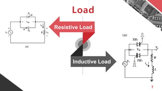
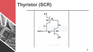
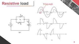
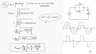
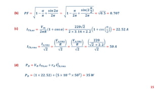
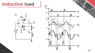
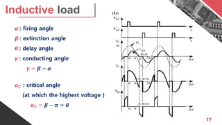
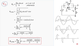
The document discusses AC-AC converters, detailing their operation, applications, and calculations involving resistive and inductive loads. It explains the use of thyristors, the determination of load power, average and RMS currents, and power factors through specific examples. References are provided for further reading on power electronics and AC voltage controllers.