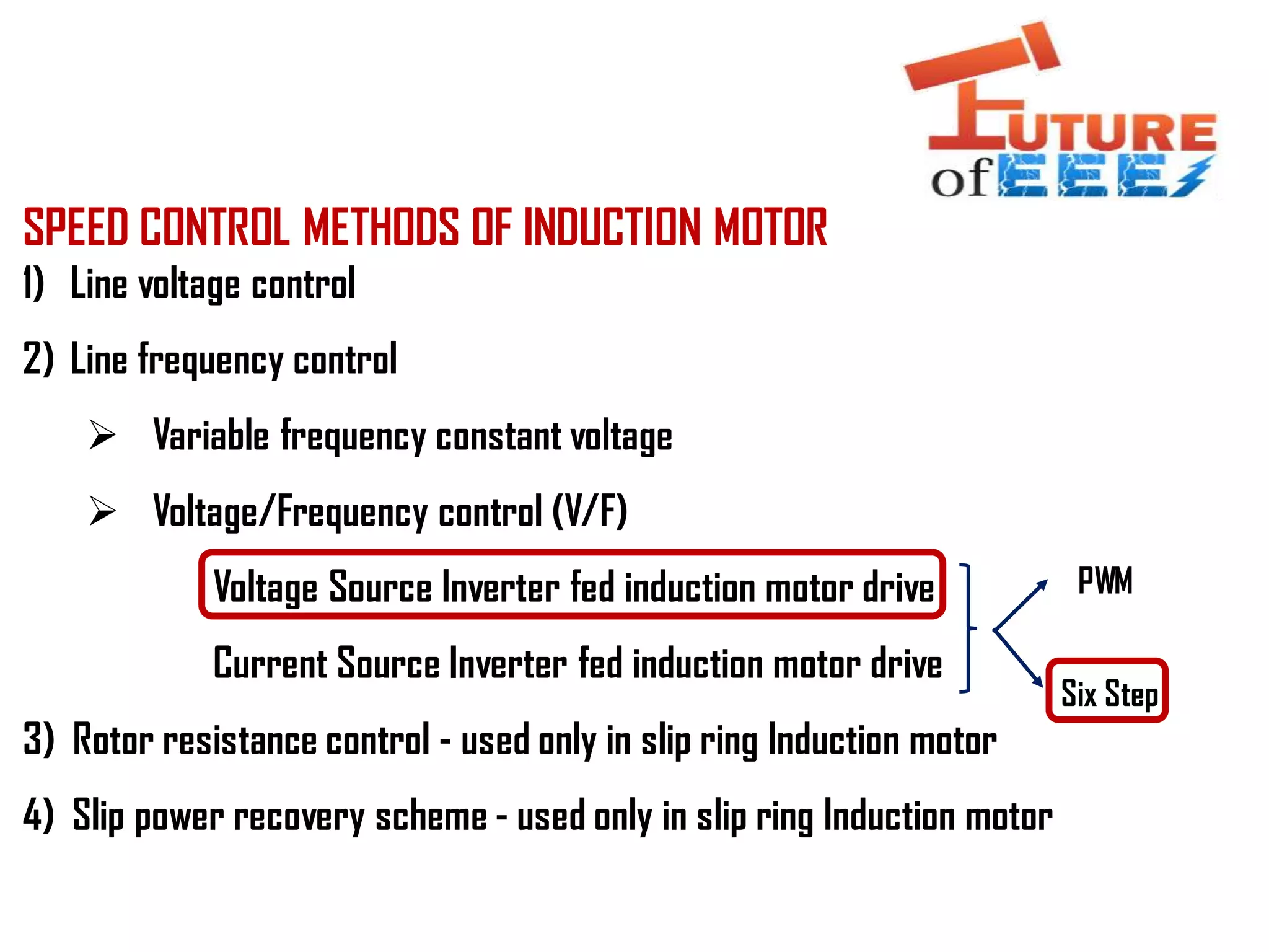
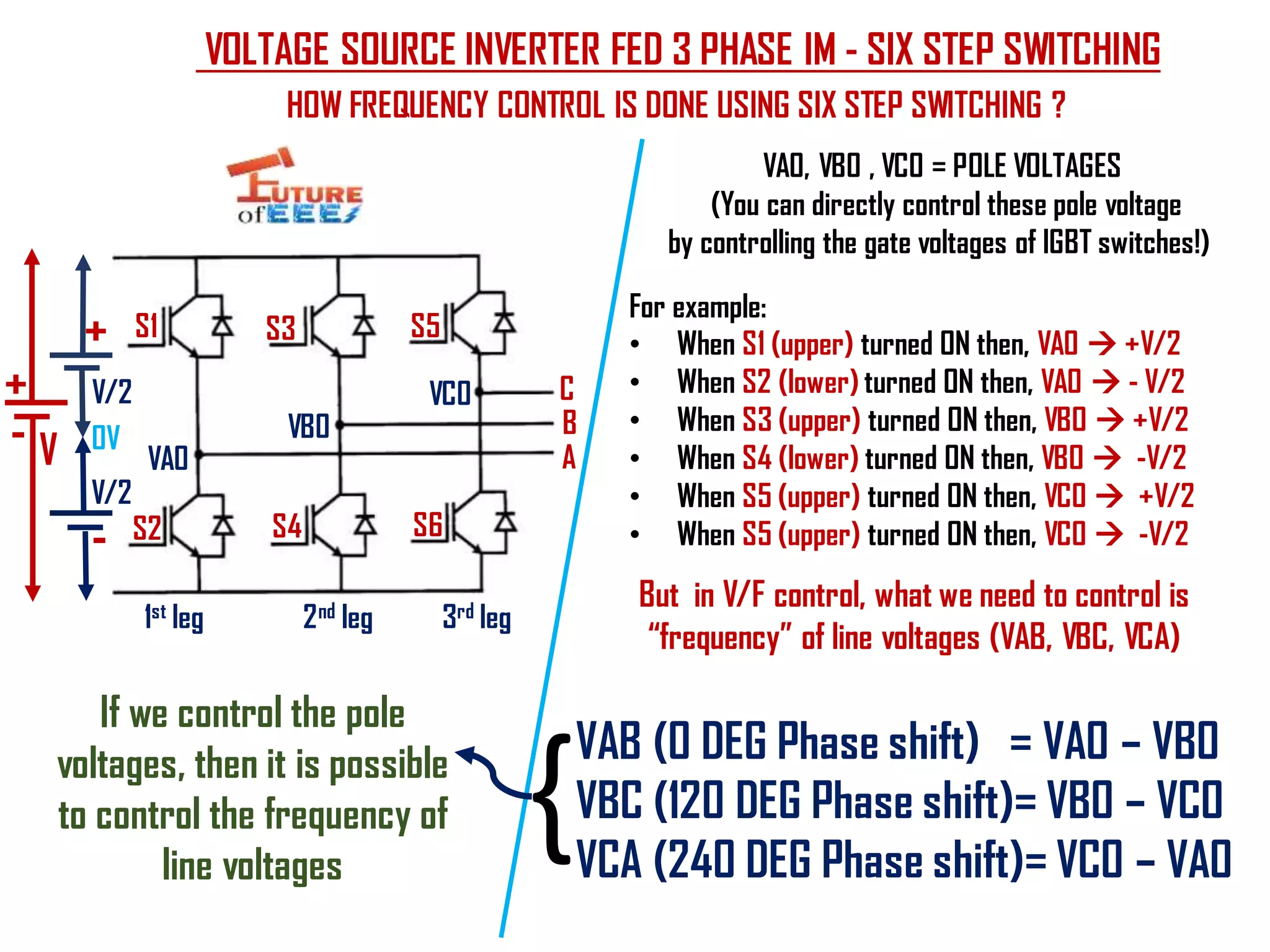
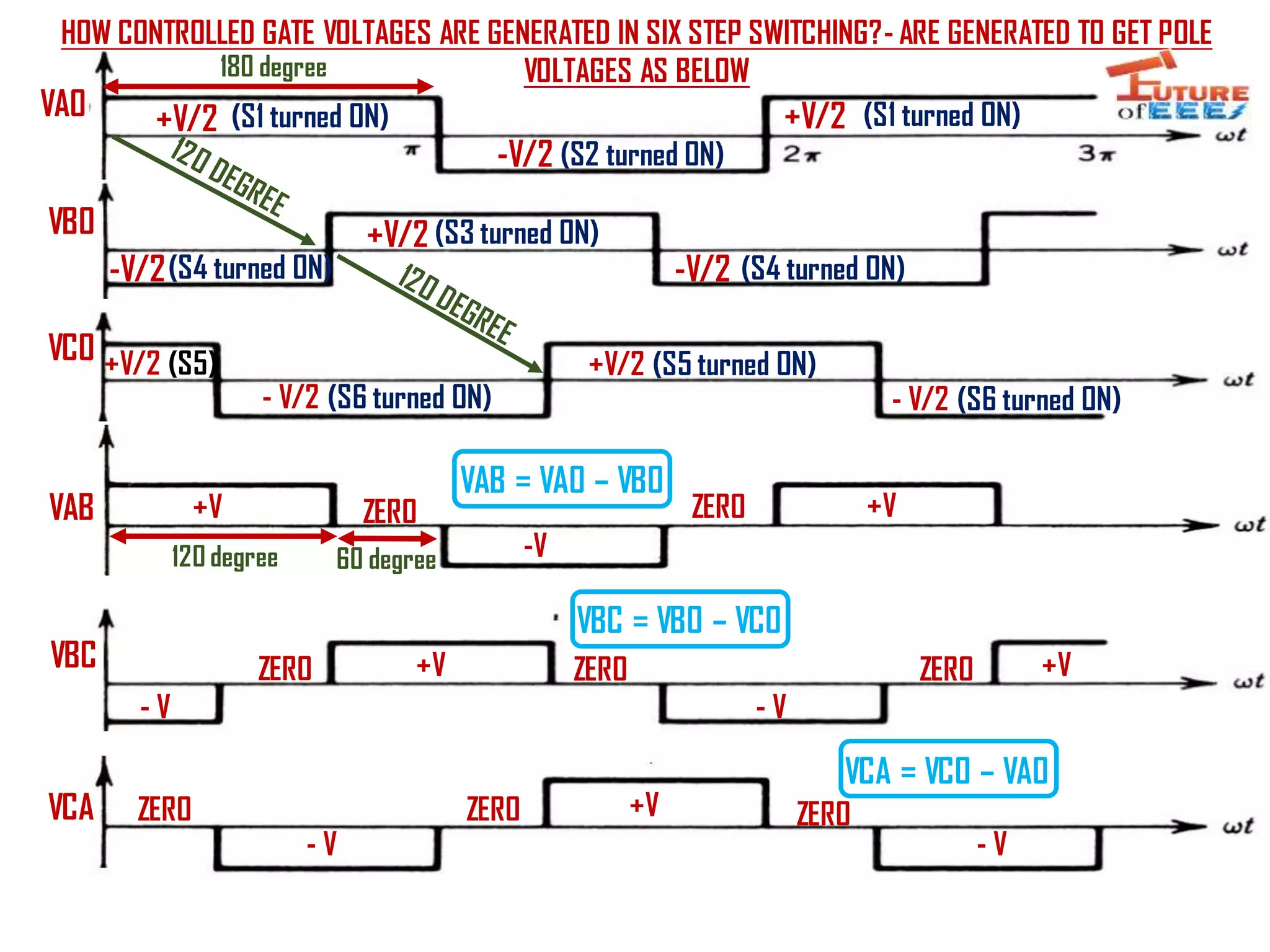
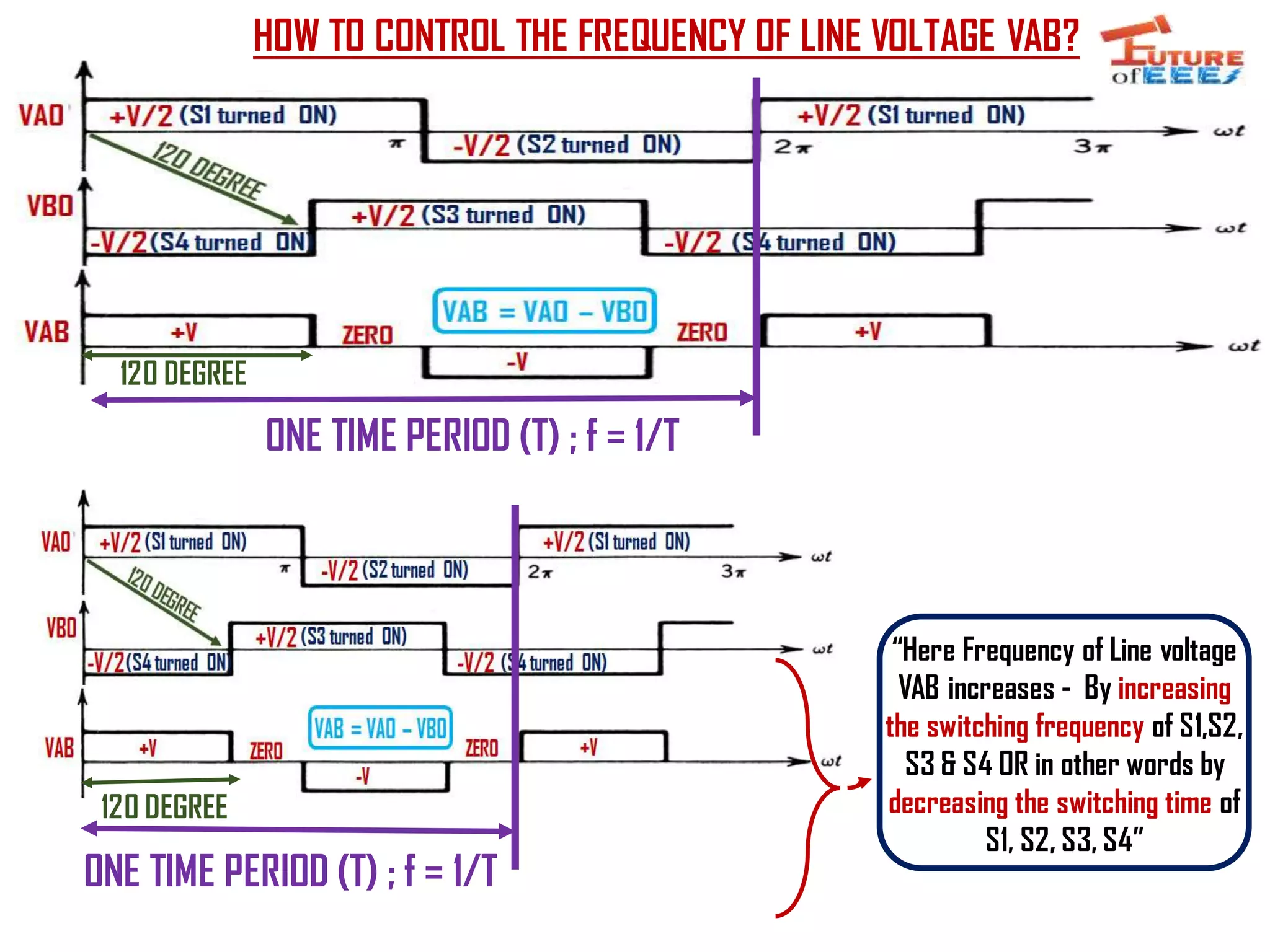
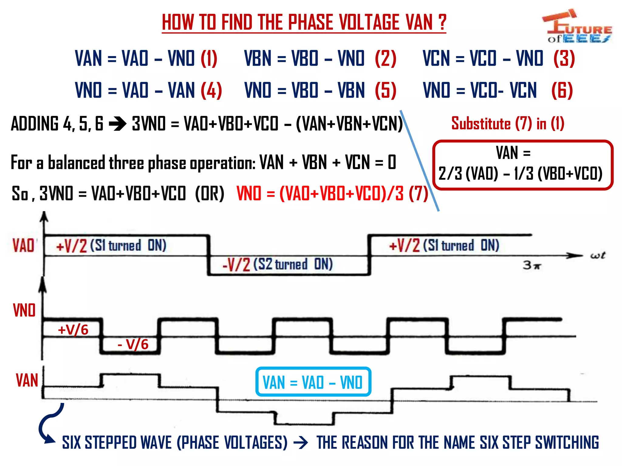
This presentation describes the Voltage Source Inverter (VSI) - Six Step Switching - Pole voltages and its control - Frequency control of line voltages
single phase half bridge inverter, full bridge inverter, parallel inverter, load commutated inverter with working and waveforms.
download and watch the animations. it will be effective.
single phase bridge inverter harmonic analysis.
A cycloconverter is a device that converts AC power at one frequency to a different output frequency in a single stage. There are several types of cycloconverters including matrix, single-phase to single-phase, single-phase to three-phase, and three-phase to three-phase. Cycloconverters are used to control the speed of AC machines in applications like cement mill drives, ship propulsion, rolling mills, and variable speed power generation. The document recommends incorporating a power-storing device to help filter harmonics produced by cycloconverters and provide backup power during interruptions.
Unit-2 Three Phase controlled converter johny renoald
This document discusses three phase controlled rectifiers. It provides equations and diagrams for a three phase half-wave converter with an RL load operating under continuous and constant load current. The average output voltage is derived as one-third the peak phase voltage multiplied by 2/π. Waveforms at different trigger angles are shown. Methods for calculating the maximum, RMS, and normalized average output voltages are also presented.
This document describes a three phase inverter that converts DC voltage to AC voltage. There are two main modes of conduction for a three phase inverter - 180 degree conduction and 120 degree conduction. 180 degree conduction involves three switches being on at a time, while 120 degree conduction only has two switches on at a time. The document provides circuit diagrams and equations to calculate the output voltages under each conduction mode. Waveforms are also shown to illustrate the phase and line voltages.
speed control of three phase induction motorAshvani Shukla
This document summarizes various methods for controlling the speed of three-phase induction motors. It discusses that induction motors are commonly used in industry due to their low cost and rugged construction but operate at constant speed. Various speed control methods are then outlined, including stator voltage control, stator frequency control, and stator current control. V/F control is also explained in detail along with its advantages for providing efficient motor speed control. The document concludes by discussing applications in industry and topics for further research.
Inverter is a device which convert a DC input supply voltage into symmetric AC voltage of desired magnitude and frequency at the output side. It is also know as DC-AC converter.
Ideal and practical inverter have sinusoidal and no-sinusoidal waveforms at output respectively.
If the input dc is a voltage source, the inverter is called a Voltage Source Inverter (VSI). One can similarly think of a Current Source Inverter (CSI), where the input to the circuit is a current source. The VSI circuit has direct control over ‘output (ac) voltage’ whereas the CSI directly controls ‘output (ac) current.
A chopper is a static device that uses pulse width modulation or variable frequency control to obtain a variable DC output voltage from a constant DC input voltage. Choppers are widely used to control motors and regenerate braking energy. The document describes different types of choppers - Type A chops the input voltage to produce positive output voltage and current. Type B allows regenerative braking by producing negative current. Type C operates in both quadrants while Type D's output voltage can be positive or negative.
This document discusses inverters and methods for controlling output voltage and reducing harmonic content. It begins by defining an inverter as a device that converts DC to AC power. It then covers classifications of inverters and different types including voltage source inverters and current source inverters. The document focuses on methods for controlling output voltage, including external control of AC voltage, external control of DC voltage, and internal control using pulse width modulation. It also discusses techniques for reducing harmonic content, such as multiple pulse modulation, sinusoidal pulse modulation, transformer connections, and stepped wave inverters.
Torque Production & Control of Speed in Synchronous Motor.
Speed of synchronous motors can be controlled using two methods called open loop and close loop control.
Open loop contol is the simplest scalar control method where motor speed is controlled by independent frequency control of the converter.
In case of close loop self control mode, instead of controlling the inverter frequency independentaly, the frequency and the phase of the output waveform are controlled by an absolute position encoder mounted on the machine shaft giving an account of position of the rotor.
This document discusses a 3-phase PWM inverter. It begins by defining an inverter as an electronic device that converts DC to AC. It then explains that PWM inverters use pulse width modulation technology to control the width of switching pulses and thereby regulate the output AC voltage. The document presents the block diagram of a 3-phase PWM inverter and describes how PWM signals are generated for each phase. It notes that 3-phase PWM inverters are used in applications like solar panels, motor speed control, and HVDC power transmission.
Cycloconverters are used to convert AC power directly to AC power of variable magnitude and frequency. They have four main advantages over conventional AC to DC to AC conversion: they do not require an intermediate DC link, allow bidirectional power flow, can produce high quality sine waves at low frequencies without filters, and are line commutated without a separate commutation circuit. Cycloconverters are commonly used to drive large induction and synchronous motors at frequencies from 0-20Hz, such as in cement mill, ship propulsion, rolling mill, and mine applications. However, they have disadvantages of not allowing smooth stepless frequency control, producing more distortion at low frequencies, and having a more complex control circuit design.
The document presents information on a PWM rectifier. It discusses that a PWM rectifier is an AC to DC power converter using controlled semiconductor switches. It has features like bi-directional power flow, nearly sinusoidal input current, unity power factor regulation, and low harmonic distortion. The document includes a circuit diagram of a PWM rectifier and mentions it can be a current or voltage type. Advantages are listed as reduced harmonics and controlled output voltage. Future applications are in traction and as an active filter. The future scope is reduced input harmonics and improved power factor for PWM rectifiers.
To turn on a Thyristor, there are various triggering methods in which a trigger pulse is applied at its Gate terminal. Similarly, there are various techniques to turn off a Thyristor, these techniques are called Thyristor Commutation Techniques.
The document discusses cycloconverters, which are devices that convert AC power at one frequency to AC power at another frequency in a single stage using thyristors. It describes the different types of cycloconverters including step-up, step-down, single phase, and three phase cycloconverters. It also discusses the principles, components, applications, advantages, and disadvantages of cycloconverters.
This document describes a project to control the speed of a single-phase induction motor. It uses components like op-amps, opto-isolators, SCRs, and a potentiometer. An op-amp operates in comparator mode to generate pulses that trigger SCRs connected in series with the motor. This allows adjusting the firing angle to control motor speed or lamp brightness. Single-phase induction motors are widely used because they are inexpensive and can operate from a single-phase power supply.
This document summarizes Preetam Jadhav's final seminar presentation on voltage source inverters. The presentation covers types of inverters including current source inverters and voltage source inverters. It then discusses different types of voltage source inverters such as multilevel diode neutral point clamped inverters and cascaded H-bridge inverters. The presentation also examines control systems, filter types, modulation schemes and excitation modes for voltage source inverters. Finally, it reviews conclusions and references presented in the seminar.
1. Shunt compensation involves connecting FACTS devices in parallel with transmission lines to act as controllable current sources.
2. There are two types of shunt compensation: shunt capacitive compensation improves power factor by injecting a leading current, while shunt inductive compensation increases power transfer capability by reducing voltage amplification.
3. Examples of FACTS devices for shunt compensation include STATCOM, SVC using TCR, TSC and TSR to continuously or stepwise vary the equivalent reactance.
The document discusses reactive power and voltage control in power systems. It defines voltage collapse as occurring when the system is unable to meet the reactive power demand, typically due to heavy loading, faults, or insufficient reactive power generation/compensation. Voltage collapse can be studied by examining the generation, transmission, and consumption of reactive power in the system. The nature of voltage collapse can be transient or long-term depending on the time scale of the disturbance and system components involved. Analytical methods for assessing voltage stability treat the system as a two-bus model and define a critical voltage and reactance value below which the system becomes unstable. Reactive power support measures are needed to maintain voltage stability.
Reactive power is necessary to maintain adequate voltage levels to transmit active power across transmission systems. It is required for system reliability and to prevent voltage collapse. Voltage is controlled by managing the production and absorption of reactive power on the system. Both insufficient reactive power and excessive reactive power can cause voltage issues and equipment problems if voltage is not properly regulated. Reactive power reserves are also required to maintain voltage stability under contingency events like generator or transmission line outages.
This document summarizes a seminar presentation on current source inverters (CSI). It introduces CSI and compares them to voltage source inverters. CSI use thyristors as self-commutating switching devices and do not require antiparallel diodes for current reversal. The document outlines the contents which include single phase CSI with ideal switches, advantages and disadvantages of CSI, single phase capacitor commutated CSI, and single phase auto sequential commutated inverter. Advantages of CSI include not requiring feedback diodes, simple commutation, and inherent short circuit protection for the supply. Disadvantages include high reverse voltages requiring devices like SCRs and continuous discharging of commutating
This document discusses four types of modifications that can be made to an existing power network to revise the Z-bus representation. Type 1 involves adding a branch impedance between a new bus and the reference bus. Type 2 adds a branch between a new bus and an existing bus. Type 3 adds a branch between an existing bus and the reference bus. Type 4 adds a branch between two existing buses. The document presents figures to illustrate each type and provides the corresponding equations to update the Z-bus matrix for the network.
This document discusses DC motor drives. It provides an overview of DC drives, including their applications, advantages, and types. It describes the basic characteristics and operating modes of shunt, series, and separately excited DC motors, including motoring, regenerative braking, dynamic braking, and plugging modes. It also discusses four quadrant operation of DC motors.
The document discusses converter configurations and analyzes a 12 pulse converter. It begins by explaining pulse number and valve/switch types in converters. It then discusses how converter configuration is selected based on pulse number to maximize valve and transformer utilization. It provides equations for peak inverse voltage, utilization factor, and transformer rating calculations. Finally, it analyzes a 12 pulse converter, explaining how two transformers connected in star-star and star-delta configurations produce 12 pulses of output with each pulse having a 30 degree duration.
Simplified analysis of graetz circuit copy - copyVert Wheeler
The document summarizes the analysis of a Graetz circuit, which is used in HVDC transmission, under two scenarios: without overlap and with overlap between thyristor valves. In the without overlap scenario, the analysis assumes valves switch on and off instantaneously with no two valves on at once. This allows simplifying the circuit to determine voltage and current waveforms. When overlap is considered and two valves can be on simultaneously, the analysis is more complex with different operation modes identified depending on the overlap angle. Key aspects of voltage, current, power factor and harmonics are derived.
A dual converter is an electronic device that combines two bridges, where one bridge acts as a rectifier to convert AC to DC and the other acts as an inverter to convert DC back to AC. There are two main types - single phase and three phase dual converters. In operation, one converter acts as a rectifier while the other acts as an inverter to provide reversible DC power. Dual converters are commonly used for speed control of DC motors in industrial applications where reversible DC power is required.
The document discusses speed control methods for DC motors. It describes various types of speed control for DC series and shunt motors, including flux control, armature voltage control, potential divider control, and applied voltage control. It also discusses the Ward-Leonard system of speed control, which uses a motor-generator set to provide smooth and rapid variable speed control and is commonly used for elevators and industrial machinery. The document outlines advantages like smooth wide range speed variation but also disadvantages like low efficiency and high initial cost.
DC-DC converters are circuits that convert a DC voltage to another DC voltage level. They use switching elements like transistors and power switches to efficiently step up or step down voltage. The buck converter is a common DC-DC converter topology that can step down voltage. It uses a switch, inductor, diode, and capacitor. By periodically opening and closing the switch, the inductor filters the output to produce a lower average voltage. The output voltage of an ideal buck converter is equal to the input voltage multiplied by the duty cycle of the switch. Real converters have non-ideal components that cause additional voltage ripple. Proper component selection and design considerations are needed to minimize ripple.
Three phase inverter - 180 and 120 Degree Mode of ConductionMalarselvamV
The document describes the operation of a 3-phase inverter that generates 3-phase AC voltage from a DC source using switches in both 180 degree and 120 degree conduction modes. In the 180 degree mode, each switch is closed for 180 degrees before the next switch closes. In the 120 degree mode, each switch is closed for 120 degrees. Tables show the switch states and resulting phase and line voltages for each 60 degree period. While the output waveforms are not pure sine waves, they approximate the desired 3-phase voltages. The inverter circuit provides a simple example for understanding 3-phase inverter operation.
The document describes the operation of a 3-phase inverter in both 180 degree and 120 degree conduction modes. In 180 degree mode, each switch is closed for 180 degrees before the next switch closes. In 120 degree mode, each switch is closed for 120 degrees. The document provides the switching sequences and corresponding phase and line voltages for each conduction mode. It concludes that both modes produce an approximated 3-phase output voltage, though not a pure sine wave, to demonstrate the basic operation of a 3-phase inverter.
Comparator, Zero Crossing Detector and schmitt trigger using opampDivyanshu Rai
This document summarizes several comparator circuits that use operational amplifiers (OP-AMPs). It discusses the basic comparator, zero crossing detector, and Schmitt trigger. The basic comparator compares two analog voltages and outputs a saturated voltage based on which input is larger. A zero crossing detector converts a sine wave to a square wave by detecting when the input crosses zero. A Schmitt trigger adds positive feedback to the comparator, resulting in hysteresis where the output switches at different threshold voltages on the rising and falling edges of the input signal. Applications of these circuits include analog to digital conversion and noise immunity.
This document discusses DC to AC conversion using inverters. It describes various inverter topologies including single phase half bridge and full bridge inverters as well as three phase full bridge inverters. It discusses modulation techniques such as sinusoidal pulse width modulation to generate sinusoidal AC outputs. Examples of applications like motor drives and solar power generation are provided.
This document provides an introduction to symmetrical components analysis for power system fault analysis. It discusses key symmetrical component concepts including positive, negative, and zero sequence components. Equations are presented for transforming unbalanced three-phase systems into balanced symmetrical components as well as for analyzing and synthesizing systems from the component quantities. Various fault types are reviewed including three-phase, phase-to-phase, phase-to-ground, open phase, and examples are shown of interpreting faults using symmetrical components.
1) The document discusses three-phase power theory, including basic assumptions about three AC voltage sources displaced 120 degrees in time.
2) Key concepts covered include phasors, phase rotation, resistive/inductive/capacitive loads, instantaneous and average power, and Blondel's theorem for measuring power in a multi-wire system.
3) Blondel's theorem states that the total power in an N-wire system can be determined from the readings of N-1 wattmeters.
This document provides a selection guide for magnetic contactors and starters in the SC and SW series for open type applications. It includes information on frame sizes, maximum motor capacities, operational currents, auxiliary contact arrangements, standard and optional features, and compatible overload relays for various contactor and starter models. Technical specifications and part numbers are provided for non-reversing contactors and starters in different frame sizes ranging from 0 to N5.
This document discusses different types of AC voltage controllers. It begins by introducing AC voltage controllers and how they can control power flow into a load by varying the RMS value of the load voltage using thyristors. It then describes the main types of AC voltage controllers classified by input supply type and control method. Applications such as lighting, heating and motor speed control are also outlined. The document proceeds to explain the principles and techniques of on-off control and phase control. Circuit diagrams are provided to illustrate single phase and three phase controller configurations. The document concludes by briefly discussing cycloconverters which can provide a variable output voltage and frequency.
The document describes dual operational amplifiers - the LM2904, LM358/LM358A, and LM258/LM258A. These devices consist of two independent op-amps designed to operate from a single power supply over a wide voltage range of 3V to 32V. They feature high gain, frequency compensation, and can source or sink output currents up to 30mA. The document provides detailed specifications, electrical characteristics, typical performance curves, and mechanical dimensions of the 8-pin DIP package for the devices.
Original Driver Mosfet IRS21814STRPBF IRS21814S 21814 SOP-14 New Internationa...AUTHELECTRONIC
Original Driver Mosfet IRS21814STRPBF IRS21814S 21814 SOP-14 New International Rectifier
https://authelectronic.com/original-driver-mosfet-irs21814strpbf-irs21814s-21814-sop-14-new-international-rectifier
Vf controlo of 3 phase induction motor using space vector modulationchino_749
The document describes space vector modulation (SVM), an advanced switching algorithm for voltage source inverters that controls AC induction motors. SVM gives 15% more voltage output compared to sine PWM, improving voltage utilization and minimizing total harmonic distortion and switching losses. It represents the three-phase motor voltages as vectors in space and controls motor voltage and frequency by controlling the amplitude and frequency of the reference space vector. The SVM algorithm allows generating the maximum possible line-to-line voltage of the DC bus supply voltage, improving motor torque and dynamic response over sine PWM.
John Kretzschmar presented on advanced polyphase metering on June 20, 2017. The presentation covered the evolution of meters and loads over time, from the past to present and possibilities for the future. It also discussed changes in communications and how non-linear loads have impacted the basic computations of metering. The bulk of the presentation was focused on providing an overview of three-phase power concepts including phasors, voltage and current relationships, and different connection types for three-phase systems.
The document discusses space vector modulation (SVM) of a three-phase two-level inverter. It describes how SVM represents three-phase voltages as a single rotating space vector and generates the reference space vector by switching between the inverter's active and zero states vectors. Specifically, it explains how the reference vector position is used to determine the appropriate sector and switching sequence to synthesize the vector over one sampling period.
The document discusses limitations on amplifier input common mode range and output swing due to transistor operating characteristics in different input and output stage topologies. It provides examples of how limitations can be addressed through design modifications like level shifting inputs or outputs. Complimentary input stages can provide near rail-to-rail input common mode range, while bipolar and CMOS output stages have limitations related to transistor saturation voltages and resistances that constrain the output swing.
This document discusses different types of inverters used in power electronics. It describes that an inverter converts DC power to AC power at a desired output voltage and frequency. It then classifies inverters as line-commutated and force-commutated. Various inverter circuits are presented including half-bridge, full-bridge, and three-phase inverters. The 180 and 120 degree modes of operation for three-phase inverters are explained. Pulse width modulation techniques for inverters like sinusoidal PWM and modified sinusoidal PWM are introduced. Current source inverters are also briefly discussed.
This document provides specifications for various VRLA Gel battery models for electric vehicles. It includes details on battery dimensions, voltages, capacities, charge methods and parameters. The charge method involves pre-charge, constant current, constant voltage limited current, trickle and float charge stages. The document also summarizes key features of the batteries such as extra long life, high reliability and safety, high environmental adaptability, and an environmentally friendly non-cadmium design.
Similar to Voltage Source Inverter VSI - Six Step Switching (20)
Equivalent Circuit, Phasor Diagram, Power Factor Control , V & Inverted V Cur...Citharthan Durairaj
This video describes the Equivalent Circuit, Phasor Diagram, Power Factor Control , V & Inverted V Curve of Synchronous Motor
For video please click the below link
https://www.youtube.com/watch?v=GdEAc_IHLbA&t=118s
Closed Loop I-F control using six step current source inverterCitharthan Durairaj
This document describes the Closed loop I-F control of Induction motor using six step Current Source Inverter (CSI).
For Explanation video- Please see my you tube channel - Future of EEE
V/F control of Induction Motor - Variable voltage and Variable frequencyCitharthan Durairaj
This presentation describes Principle of Variable voltage and Variable frequency- the open loop & closed loop Voltage/Frequency (V/F) control of Induction motor with torque speed characteristics -
This presentation describes the
Line Voltage Control - Torque Speed Characteristics - Methods -Advantages - Disadvantages - Applications of Voltage control
This presentation describes the per-phase equivalent circuit of induction motor - Power flow diagram - Ratio of air gap power, rotor copper loss and mechanical power developed.
Torque speed characteristics of Squirrel cage & Slip ring induction motorsCitharthan Durairaj
This video describes the Torque - Slip / Torque- Speed Characteristics of three phase squirrel cage induction motor and slip ring induction motor- also describes the Condition for the maximum torque - Pullout torque and Pullout torque equation
This presentation describes the Principle of Operation - Squirrel cage Induction motor
Classification of Induction motors
Rotating Magnetic flux- Relative Motion - Faradays law- Lenz law
This video describes the monitoring of sensor values/ random values using blynk app and FRED IoT
Steps to be done in Blynk App & Steps to be done in FRED IoT
This Presentation describes the
Introduction to IoT - What is IoT ?
An Example - Home automation - Hardware and Software
If you have questions, please don't hesitate to ask in the comment section.
Pls like, share and subscribe. Thank you!
#FutureofEEE
There are three main types of stepper motors: variable reluctance, permanent magnet, and hybrid. Variable reluctance stepper motors use changes in magnetic reluctance to rotate and can be single or multi-stack. They provide high torque but have torque ripple issues. Permanent magnet stepper motors use permanent magnets on the rotor and have bipolar drive circuits. They can achieve a 45 degree step angle through alternate single and two phase excitation. Hybrid stepper motors combine features of variable reluctance and permanent magnet motors, with a 4 pole stator and 5 pole rotor construction. Each motor type has advantages and disadvantages related to torque, torque ripple, and drive circuit complexity.
1) The document discusses permanent magnet brushless DC (PMBLDC) motors and their control. It explains that the desired current waveform for each phase must be estimated based on the instantaneous rotor position to satisfy the maximum torque at minimum current principle.
2) The desired current is provided to the phases through driver circuits containing six transistors, which are switched on based on whether the desired current is positive or negative.
3) Rotor position is typically sensed using three Hall sensors spaced 120 degrees apart, though sensorless control is also possible using back EMF measurements. Control circuit design and operation are also briefly outlined.
1) For alternators to operate in parallel, they must be synchronized by having equal line voltage, frequency, phase sequence, phase angle, and waveform.
2) When alternators are synchronized and operating in parallel with no load, a circulating current will flow if their speeds or excitations differ slightly.
3) This circulating current acts to resynchronize the alternators by speeding up the slower one and slowing the faster one through their functioning as motor and generator respectively, until steady state is reached with no circulating current.
HEAP SORT ILLUSTRATED WITH HEAPIFY, BUILD HEAP FOR DYNAMIC ARRAYS.
Heap sort is a comparison-based sorting technique based on Binary Heap data structure. It is similar to the selection sort where we first find the minimum element and place the minimum element at the beginning. Repeat the same process for the remaining elements.
Advanced control scheme of doubly fed induction generator for wind turbine us...IJECEIAES
This paper describes a speed control device for generating electrical energy on an electricity network based on the doubly fed induction generator (DFIG) used for wind power conversion systems. At first, a double-fed induction generator model was constructed. A control law is formulated to govern the flow of energy between the stator of a DFIG and the energy network using three types of controllers: proportional integral (PI), sliding mode controller (SMC) and second order sliding mode controller (SOSMC). Their different results in terms of power reference tracking, reaction to unexpected speed fluctuations, sensitivity to perturbations, and resilience against machine parameter alterations are compared. MATLAB/Simulink was used to conduct the simulations for the preceding study. Multiple simulations have shown very satisfying results, and the investigations demonstrate the efficacy and power-enhancing capabilities of the suggested control system.
CHINA’S GEO-ECONOMIC OUTREACH IN CENTRAL ASIAN COUNTRIES AND FUTURE PROSPECTjpsjournal1
The rivalry between prominent international actors for dominance over Central Asia's hydrocarbon
reserves and the ancient silk trade route, along with China's diplomatic endeavours in the area, has been
referred to as the "New Great Game." This research centres on the power struggle, considering
geopolitical, geostrategic, and geoeconomic variables. Topics including trade, political hegemony, oil
politics, and conventional and nontraditional security are all explored and explained by the researcher.
Using Mackinder's Heartland, Spykman Rimland, and Hegemonic Stability theories, examines China's role
in Central Asia. This study adheres to the empirical epistemological method and has taken care of
objectivity. This study analyze primary and secondary research documents critically to elaborate role of
china’s geo economic outreach in central Asian countries and its future prospect. China is thriving in trade,
pipeline politics, and winning states, according to this study, thanks to important instruments like the
Shanghai Cooperation Organisation and the Belt and Road Economic Initiative. According to this study,
China is seeing significant success in commerce, pipeline politics, and gaining influence on other
governments. This success may be attributed to the effective utilisation of key tools such as the Shanghai
Cooperation Organisation and the Belt and Road Economic Initiative.
Literature Review Basics and Understanding Reference Management.pptxDr Ramhari Poudyal
Three-day training on academic research focuses on analytical tools at United Technical College, supported by the University Grant Commission, Nepal. 24-26 May 2024
A review on techniques and modelling methodologies used for checking electrom...nooriasukmaningtyas
The proper function of the integrated circuit (IC) in an inhibiting electromagnetic environment has always been a serious concern throughout the decades of revolution in the world of electronics, from disjunct devices to today’s integrated circuit technology, where billions of transistors are combined on a single chip. The automotive industry and smart vehicles in particular, are confronting design issues such as being prone to electromagnetic interference (EMI). Electronic control devices calculate incorrect outputs because of EMI and sensors give misleading values which can prove fatal in case of automotives. In this paper, the authors have non exhaustively tried to review research work concerned with the investigation of EMI in ICs and prediction of this EMI using various modelling methodologies and measurement setups.
Low power architecture of logic gates using adiabatic techniquesnooriasukmaningtyas
The growing significance of portable systems to limit power consumption in ultra-large-scale-integration chips of very high density, has recently led to rapid and inventive progresses in low-power design. The most effective technique is adiabatic logic circuit design in energy-efficient hardware. This paper presents two adiabatic approaches for the design of low power circuits, modified positive feedback adiabatic logic (modified PFAL) and the other is direct current diode based positive feedback adiabatic logic (DC-DB PFAL). Logic gates are the preliminary components in any digital circuit design. By improving the performance of basic gates, one can improvise the whole system performance. In this paper proposed circuit design of the low power architecture of OR/NOR, AND/NAND, and XOR/XNOR gates are presented using the said approaches and their results are analyzed for powerdissipation, delay, power-delay-product and rise time and compared with the other adiabatic techniques along with the conventional complementary metal oxide semiconductor (CMOS) designs reported in the literature. It has been found that the designs with DC-DB PFAL technique outperform with the percentage improvement of 65% for NOR gate and 7% for NAND gate and 34% for XNOR gate over the modified PFAL techniques at 10 MHz respectively.
DEEP LEARNING FOR SMART GRID INTRUSION DETECTION: A HYBRID CNN-LSTM-BASED MODELgerogepatton
As digital technology becomes more deeply embedded in power systems, protecting the communication
networks of Smart Grids (SG) has emerged as a critical concern. Distributed Network Protocol 3 (DNP3)
represents a multi-tiered application layer protocol extensively utilized in Supervisory Control and Data
Acquisition (SCADA)-based smart grids to facilitate real-time data gathering and control functionalities.
Robust Intrusion Detection Systems (IDS) are necessary for early threat detection and mitigation because
of the interconnection of these networks, which makes them vulnerable to a variety of cyberattacks. To
solve this issue, this paper develops a hybrid Deep Learning (DL) model specifically designed for intrusion
detection in smart grids. The proposed approach is a combination of the Convolutional Neural Network
(CNN) and the Long-Short-Term Memory algorithms (LSTM). We employed a recent intrusion detection
dataset (DNP3), which focuses on unauthorized commands and Denial of Service (DoS) cyberattacks, to
train and test our model. The results of our experiments show that our CNN-LSTM method is much better
at finding smart grid intrusions than other deep learning algorithms used for classification. In addition,
our proposed approach improves accuracy, precision, recall, and F1 score, achieving a high detection
accuracy rate of 99.50%.
ACEP Magazine edition 4th launched on 05.06.2024Rahul
This document provides information about the third edition of the magazine "Sthapatya" published by the Association of Civil Engineers (Practicing) Aurangabad. It includes messages from current and past presidents of ACEP, memories and photos from past ACEP events, information on life time achievement awards given by ACEP, and a technical article on concrete maintenance, repairs and strengthening. The document highlights activities of ACEP and provides a technical educational article for members.
1. SPEED CONTROL METHODS OF INDUCTION MOTOR
1) Line voltage control
2) Line frequency control
Variable frequency constant voltage
Voltage/Frequency control (V/F)
Voltage Source Inverter fed induction motor drive
Current Source Inverter fed induction motor drive
3) Rotor resistance control - used only in slip ring Induction motor
4) Slip power recovery scheme - used only in slip ring Induction motor
Six Step
PWM
2. VOLTAGE SOURCE INVERTER FED 3 PHASE IM - SIX STEP SWITCHING
HOW FREQUENCY CONTROL IS DONE USING SIX STEP SWITCHING ?
S1 S3 S5
S2 S4 S6
VA0
VB0
VC0
A
B
C
VA0, VB0 , VC0 = POLE VOLTAGES
(You can directly control these pole voltage
by controlling the gate voltages of IGBT switches!)
For example:
• When S1 (upper) turned ON then, VA0 +V/2
• When S2 (lower) turned ON then, VA0 - V/2
• When S3 (upper) turned ON then, VBO +V/2
• When S4 (lower) turned ON then, VBO -V/2
• When S5 (upper) turned ON then, VC0 +V/2
• When S5 (upper) turned ON then, VC0 -V/2
But in V/F control, what we need to control is
“frequency” of line voltages (VAB, VBC, VCA)
VAB (0 DEG Phase shift) = VA0 – VB0
VBC (120 DEG Phase shift)= VB0 – VC0
VCA (240 DEG Phase shift)= VC0 – VA0
{
If we control the pole
voltages, then it is possible
to control the frequency of
line voltages
1st leg 2nd leg 3rd leg
V/2
V/2
V 0V
+
-
+
-
3. VA0 +V/2 (S1 turned ON)
-V/2 (S2 turned ON)
+V/2 (S1 turned ON)
+V/2
-V/2-V/2(S4 turned ON)
(S3 turned ON)
(S4 turned ON)
VB0
VC0 +V/2 (S5 turned ON)
- V/2 (S6 turned ON) - V/2 (S6 turned ON)
+V/2 (S5)
VAB
VAB = VA0 – VB0
+V ZERO
-V
+VZERO
+V +V
+V
- V
- V
- V
- V
VBC = VB0 – VC0
VBC
VCA
VCA = VC0 – VA0
ZERO ZERO ZERO
ZERO ZERO ZERO
120 degree 60 degree
HOW CONTROLLED GATE VOLTAGES ARE GENERATED IN SIX STEP SWITCHING?- ARE GENERATED TO GET POLE
VOLTAGES AS BELOW180 degree
4. ONE TIME PERIOD (T) ; f = 1/T
ONE TIME PERIOD (T) ; f = 1/T
HOW TO CONTROL THE FREQUENCY OF LINE VOLTAGE VAB?
“Here Frequency of Line voltage
VAB increases - By increasing
the switching frequency of S1,S2,
S3 & S4 OR in other words by
decreasing the switching time of
S1, S2, S3, S4”
120 DEGREE
120 DEGREE
5. HOW TO FIND THE PHASE VOLTAGE VAN ?
VAN = VA0 – VN0 (1) VBN = VBO – VN0 (2) VCN = VC0 – VNO (3)
For a balanced three phase operation: VAN + VBN + VCN = 0
VN0 = VA0 – VAN (4) VN0 = VB0 – VBN (5) VNO = VCO- VCN (6)
ADDING 4, 5, 6 3VN0 = VA0+VB0+VCO – (VAN+VBN+VCN)
So , 3VN0 = VA0+VB0+VCO (OR) VNO = (VA0+VBO+VCO)/3 (7)
VN0
+V/6
- V/6
VAN VAN = VA0 – VN0
SIX STEPPED WAVE (PHASE VOLTAGES) THE REASON FOR THE NAME SIX STEP SWITCHING
Substitute (7) in (1)
VAN =
2/3 (VA0) – 1/3 (VB0+VC0)